patent · US4474612
Vertically extending plate electrode for gas-forming electrolyzers
2 October 1984
Page 1 — bibliographic record
United States Patent (19) 11 Patent Number: 4,474,612 Lohrberg 45 Date of Patent: (Oct. 2, 1984 54) VERTICALLY EXTENDING PLATE FOREIGN PATENT DOCUMENTS
ELECTRODE FOR GAS-FORMING
ELECTROLYZERS 453750 12/1927 Fed. Rep. of Germany .
75) Inventor: Karl Lohrberg, Heusenstamm, Fed. 1028153 5/1953 France . Rep. of Germany
Primary Examiner-John F. Niebling 73) Assignee: Metallgesellschaft Aktiengesellschaft, Attorney, Agent, or Firm-Karl F. Ross; Herbert Dubno Frankfurt am Main, Fed. Rep. of 57 ABSTRACT
Germany
In gas-forming electrolyzers, particularly membrane 21 Appl. No.: 520,068 electrolyzers having vertically extending plate elec trodes, each electrode plate is divided into horizontal 22 Filed: Aug. 3, 1983 strips and the entire active electrode surface is parallel 30 Foreign Application Priority Data to the counterelectrode and spaced from it as closely as possible. The top portions of each of the horizontal
Aug. 3, 1982 DE Fed. Rep. of Germany ....... 3228884 strips into which the electrode is divided define gas escape paths and extend away from the counterellec 51) int. Cl. ......................... C25B 9/00; C25B 11/03 trode. To improve the degassing of the electrolyte the 52 U.S. Cl. .................................... 204/252; 204/283; ratio of the distance G between the counterellectrode or 204/284 membrane and the gas-defining line S at the lower edge 58 Field of Search ........................ 204/283, 284, 252 of each electrode strip to the distance E between the 56 References Cited counterelectrode or membrane and the breakaway edge K of the angled portion defining the gas escape path
1,771,091 7/1920 Lawaczeck ......................... 204/101 than 0.6, 4,142,950 3/1979 Creamer .............................. 204/284 4,252,628 2/1981 Boulton ........................... 204/290 R 11 Claims, 3 Drawing Figures
Page 2
Drawing sheet — no readable text.
Page 3
Drawing sheet — no readable text.
Page 4
active surface area, inadequate stability and loss of high
VERTICALLY EXTENDING PLATEELECTRODE grade coating material on the rear of the electrode. FOR GAS-FORMINGELECTROLYZERS It has been proposed in German Patent document
No. 2,059,868 to provide in gas-forming diaphragm
CROSS REFERENCE TO RELATED 5 cells having vertically extending electrodes, a plate
APPLICATION electrode which consists of several plates having sur
This application is related to the commonly assigned faces for guiding the escaping gas which has been copending application Ser. No. 507,840 filed June 24, formed.
1983. The inclination of the guiding plate inevitably re 10 sulted in different distances from the active surface to
FIELD OF THE INVENTION the counter electrode, French Pat, No. 1,028,153 dis This invention relates to a vertically extending plate closes an electrolyzer in which the electrodes are paral electrode for gas-forming electrolyzers, which plate is lel and have the smallest possible spacing. The known horizontally divided into electrode strips by slits (sepa electrodes openings consist of one or more strips which define rations); the top portion of each strip extends away from 15 horizontal strips and opposing formed by an angled portions of the the escape of gas with the smallest the counterelectrode to define the gas escape paths possible resistance. The angled portions extend away formed by the slits. from the counter-electrode so that the active surface More particularly, the invention relates to the rela area is not appreciably reduced. A similar electrode tionship between an electrode formed with slit-like 20 arrangement is known from German Pat. No. 453,750. openings extending horizontally for the escape of gases, These electrodes are formed with cuts, which permit which may be juxtaposed with a planar member, gener portions of any desired configuration to be bent out so ally a membrane as described in the above-identified that they extend away from the counterelectrode. copending application, or a counter-electrode, in a gas While such electrodes, particularly cathodes, have producing electrolysis cell, 25 been known for more than 30 years, they have not been BACKGROUND OF THE INVENTION commercially exploited, but perforated sheet metal, In electrochemical processes it is essential to ensure a expanded metal or similar materials are still employed, uniform distribution of the current over the electrode OBJECT OF THE INVENTION surface. That uniform distribution is influenced by the 30 It is an object of the invention to provide an electrode throwing power of the electrolyte and by the homoge which can be used with a minimum spacing ratio and neity of the electrodes. The throwing power will in yet ensures a reliable and rapid escape of gas from the crease with the surface area on which the current flow electrolyte.
lines are incident on the counterelectrode. While an inadequate throwing power can be compensated by an 35 SUMMARY OF THE INVENTION increase of the interellectrode distance, this will increase This object is accomplished according to the inven the voltage drop across the cell. tion in a vertically extending plate electrode for gas If inhomogeneities are present in the surface of the forming electrolyzers, particularly membrane electro electrode, the flow of current will result in local distor lyzers, comprising horizontal strips having an active tions. For this reason the interelectrode distance i.e., the 40 electrode surface, which strips throughout their active distance between the anode and the cathode, is of great electrode surface are parallel to the counterelectrode importance. In membrane electrolytic cells having a and have the smallest possible distance therefrom membrane and producing gases, such as chlorine, oxy whereas the top portion of each of the strips extends gen, hydrogen, it is difficult to maintain or adjust a small away from the counter-electrode and defines a gas es interelectrode distance and the gas bubbles cannot es 45 cape path.
cape as quickly as is required if the interelectrode dis In an electrode assembly of this kind the invention tance is small. resides in that the ratio of the distance G between the Any gas present in the electrolyte between the elec counter-electrode or membrane and the gas-dividing trode will reduce the electrical conductivity of the line 5 at the lower edge of each electrode strip to the electrolyte so that the power consumption will be in 50 distance E between the counterellectrode or membrane creased. In addition, microscopic distortions of the sur and the breakaway edge K of the angled portion defin face of the electrode may be caused by the electric ing the gas escape path corresponds to a value F (degas current. The evolution of gas also gives rise to turbu sing capability) below 0.6.
lence in the electrolyte. A turbulent motion of the elec It has been found that the above-mentioned ratio trolyte has the disadvantage that the membrane is sub 55 results in a degassing of the electrolyte-gas suspension jected to intense mechanical stress. In order to avoid an to a particularly desirable degree and in an expansion of accelerated destruction of the membrane it is generally the gas which is released and ensures that a major por necessary to restrict the height of the electrodes, to tion of the gas will flow behind the next upper electrode select a considerable distance between the electrodes of strip so that the electrolysis at said upper electrode strip the cell, and to limit the electric current density al 60 will not be adversely affected or will not be adversely though this will adversely affect the energy efficiency affected to an appreciable degree. of the electrolytic cell and its productivity. When reference is made herein to the distance be To reduce the disadvantages of electrolytic cells tween the counterelectrode and the gas-defining line or having membranes and vertically extending electrodes the distance between the counterelectrode and the it is usual to employ electrodes having openings for the 65 break-away edge, it will be understood that these dis escape of the reaction gases. Such electrodes may con tances are measured horizontally and perpendicular to sist of perforated electrodes, wire mesh or expanded the plane of the counterelectrode which is generally metal. The disadvantages reside, inter alia, in a smaller disposed vertically. The gas-defining line is the line at
Page 5
which gas passing upwardly is determined to pass be BRIEF DESCRIPTION OF THE DRAWING tween the plane of the electrode provided with the passages and the plane from which the distance is mea The above and other objects, features and advantages sured as described previously Gas to the other side of 5 of the present invention will be more readily apparent this line is generally directed behind the electrode. from the following description, reference being made to the accompanying drawing in which:
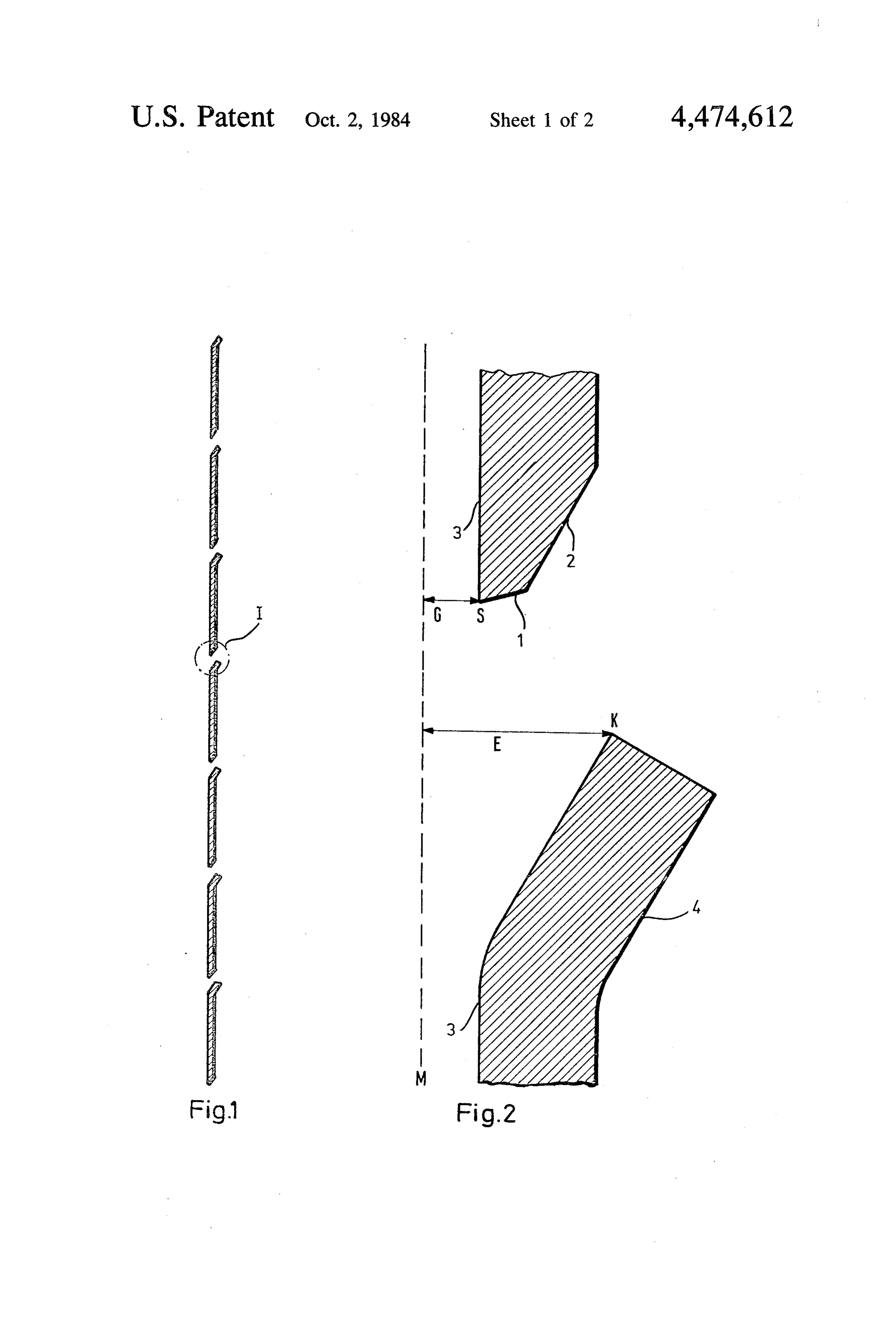
It is, therefore, of interest to describe the electrode as having a front and a back. The front surface of the FIG. 1 is a vertical section through a plate electrode electrode is that surface which is most closely juxta according to the invention;
posed with the counter-electrode. When the horizontal 10 FIG. FIG.
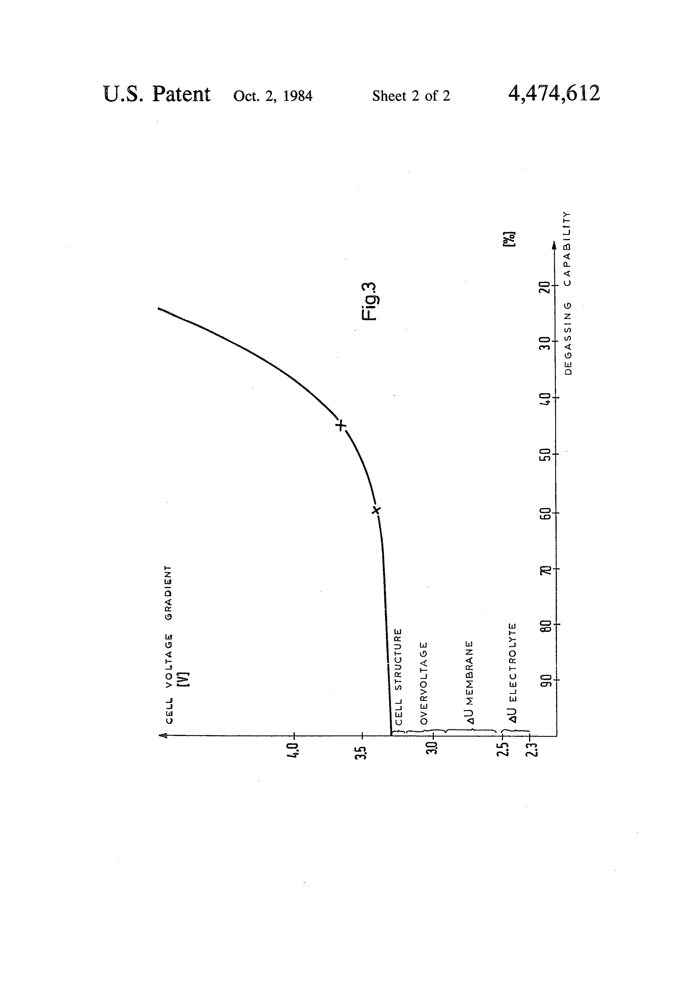
2 is a detail view of the region II of FIG. 1; and 3 is a graph illustrating the invention.
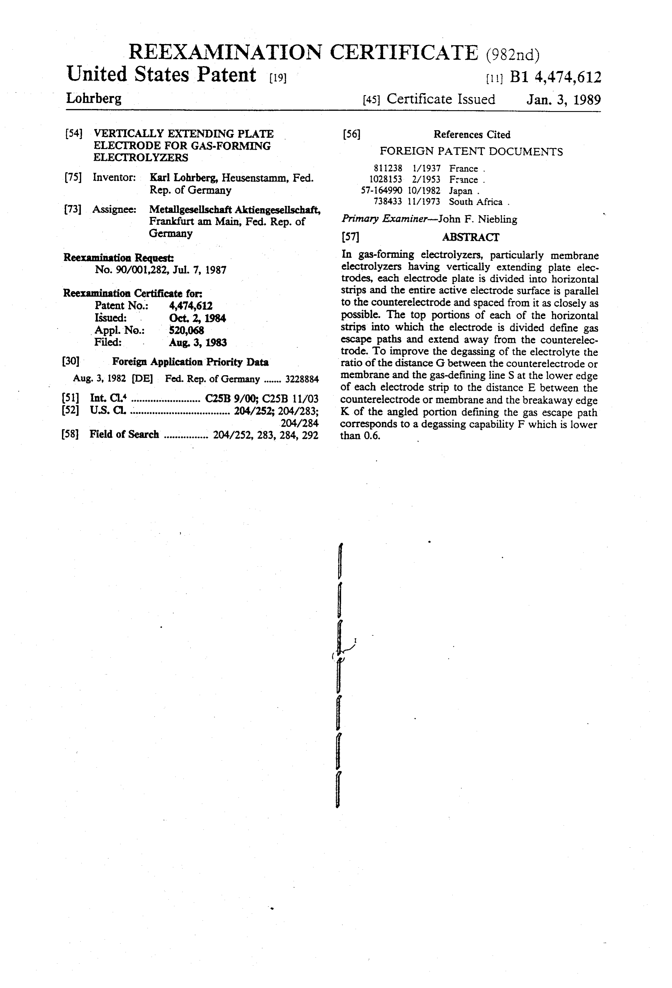
slits defining the gas passages are delimited by a cham fer, the upper edge of this chamfer is inclined down SPECIFIC DESCRIPTION wardly and forwardly, the break-away line is the line at which the plane of the chamfer meets the plane of the tionThe is electrode arrangement according to the inven shown by way of example in FIGS. 1 and 2 of the front of the electrode. If there is no chamfer or if there 15 is a chamfer in the opposite direction, i.e. the chamfer is trode which is 1 horizontally drawing. FIG. is a side elevation showing an elec divided into individual downwardly and rearwardly, the break-away line can strips having angled portions which define gas escape be the rearmost edge of the upper board of the slit. paths. (The electrode frame and current supply termi Of course, when a membrane is utilized, the horizon nals are not shown.)
tal distances measured from the gas-defining line and 20 FIG. 2 shows the detail which is designated "A' in the break-away edge will be measured to the plane of FIG. 1. In FIG. 2, M designates the membrane, 5 the the member which is proximal to the electrode formed gas-dividing line at the lower end of the plate strip, K with the passages. Thus, this membrane and the coun the breakaway edge of the angled top portion of the terelectrode can be considered planar members juxta next lower strip, G the distance M-S and E the distance posed with the passage-forming electrode and the dis 25 M-K.
tance in question is measured to the most proximal sur In the chamfered electrode shown in FIG. 2, the face of the member which is most directly juxtaposed gas-dividing lines extends in the plane of the active with the electrode. surface 3 at the lower edge of the downwardly and The angled portion of each strip of the electrode 30 forwardly extending chamfer, which in term lies for according to the invention generally consists of a flat wardly of the downwardly and forwardly inclined level surface, but may also be curved. The angle included by 2. In electrodes which are not chamfered it is assumed the angled portion and the electrode plane generally that the gas-dividing line lies on the center plane of the amounts to between 15 and 70. Each plate may have a electrode. The term "degassing capability' is used in height of 5 to 50 centimeters and a thickness of about 1 35 consideration of the fact that the gas rising from the to 3 millimeters. The slit width can be 1 to 10 times this interelectrode gap will expand as far as to the breakway thickness. The thickness of each electrode strip will be edge K and will then rise vertically and will be divided selected in view of the width of the electrode because at the gas-dividing line into a portion which enters the no additional current distributing pins are provided, interelectrode gap and a larger, second portion which in accordance with the invention flows behind the elec which are required, e.g., in cells which have conven 40 trode.
tional dimensions and in which expanded metal is used In a commercial plant for the production of sodium to form the active surface.
chloride
The electrode plates are fixedly installed in known which plant solution by an electrolysis of alkali chloride, manner in a frame which has terminals for the supply of 45 dium comprised ion-selective membranes, a so electric current. chloride solution having a concentration of 320 The electrode according to the invention may be grams per liter was electrolyzed. The current density used as an anode or cathode in electrolytic processes amounted electrolyte to 3.1 kA/m2 and the temperature of the amounted to 80 C.
using a membrane. When used as an anode, the elec The cathodes consisted of electrodes according to the trode can consist of titanium, tantalum, tungsten or 50 invention in which the individual plate strips had a zirconium. In that case the electrode is provided with height of 14 centimeters and the active surfaces an activating coating only on its surface facing the amounted to about 90% of the projected area. The counterelectrode. That activating coating may consist material consisted of St 37 steel having no activation. A in known manner, of metal oxides or of metals of the comparison was made with conventional cathodes con group platinum, iridium, osmium, palladium, rhodium, 55 sisting of the same material in the form of expanded ruthenium. If the electrode according to the invention is metal and having the same active surface area relative used as a cathode in electrolytic processes using a mem to the projected area. The counterelectrodes consisted brane, the electrode may consist, e.g. of steel or nickel of dimensionally stable anodes. The selective mem or alloys thereof. branes consisted of pefluorinated ion exchanger mem The electrode plate according to the invention can be 60 branes (trade name Nafion). Each plate had a thickness installed in electrolyzers having membranes. In connec of 6.5 mm and a width of 100 centimeters. The angled tion with the invention, the term "membrane cells' is portion 4 which defined the gas escape path included used to describe only cells which have ion-selective (as shown) an angle of 30' with the surface 3. The width membranes, such as perfluorinated cation exchanger of the gap between adjacent plate strips amounted to 20 membranes. Such membranes can be used to separate 65 mm. The distance between the surfaces of the cathode cathodic and anodic products of an electrolysis from and membrane amounted to 3 mm. The total electrode each other or from the reactants supplied to the respec surface amounted to 1x1 m2.
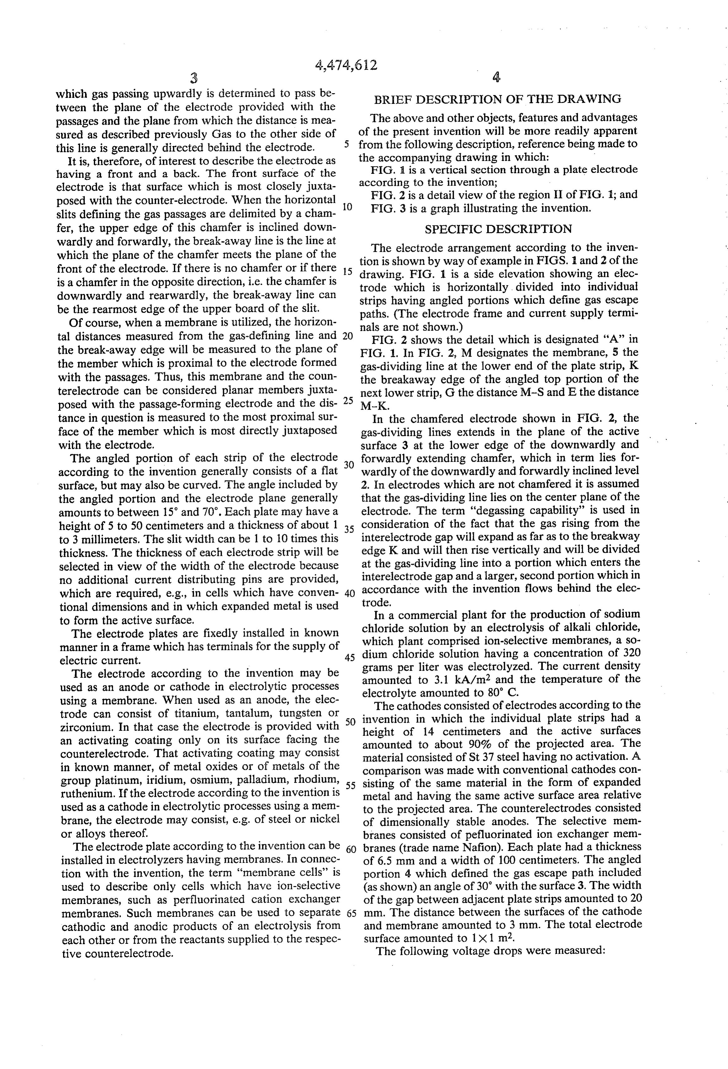
tive counterelectrode. The following voltage drops were measured:
Page 6
5. The improvement defined in claim 4 wherein said
electrode is a plate of a thickness of substantially to 3
Strip cathode I according to the invention 3.40 volts
Strip cathode II according to the invention 3.65 volts 6. In a gas-generating electrolysis cell having a verti 5 cal oriented passage-forming electrode juxtaposed with a planar member participating with the electrode in a
If the distance M-S (see FIG. 2) is designated G and gas-generating electrolysis action and wherein said pas the distance M-K is designated E (expansion space), the sages are horizontal slit-like gaps formed in said elec degassing capability (expansion capability) F (%) equal trode, the improvement wherein in combination: to the ratio of G to E will be as follows 10 each of said gaps is defined by an upper boundary and said electrode is a plate of a thickness of substan
GE F (%) tially 1 to 3 mm and has a forward planar surface
With strip cathode I 0.45 55 juxtaposed with and parallel to said member; With strip cathode II 0.60 40 a lower limb of each of said gaps is defined by a 15 rearwardly extending portion including an angle of about 30' with said surface and having a break
If a curve is plotted with calculated values for a de away edge at the top thereof located rearwardly of gassing capability of 100% and a degassing capability of said surface, said rearwardly extending portion 0%, the measured points will lie on the curve of the having a width less than that of said surface in graph shown in FIG. 3, in which the voltage drop has 20 vertical direction, said upper boundary being de been plotted against the degassing capability. fined by a downwardly and forwardly extending The advantages afforded by the electrode plate ac bevel terminating forwardly of said break-away cording to the invention reside in that the electrode edge and having a gas-dividing line separating gas plate may be spaced from the counterelectrode as rising forwardly of said surface from gas deflected closely as possible and may be completely activated on 25 rearwardly of said electrode said bevel terminating its surface which is parallel to the counterelectrode and at a downwardly and forwardly extending chamfer a local overheating of the temperature-sensitive mem forming said gas-dividing line at said surface; and brane will be avoided. The gas evolved between the the ratio between the horizontal distance G between anode and the cathode is permitted to escape quickly said gas-dividing line and said member and the from the region behind the active surface to the region 30 horizontal distance E between said break-away behind the electrode. The electrodes can be made from edge and said member is less than 0.6, said gaps flat sheet metal in a simple manner and with a low ex having widths of substantially one to ten times the penditure. An active surface layer may be applied to thickness of said plate.
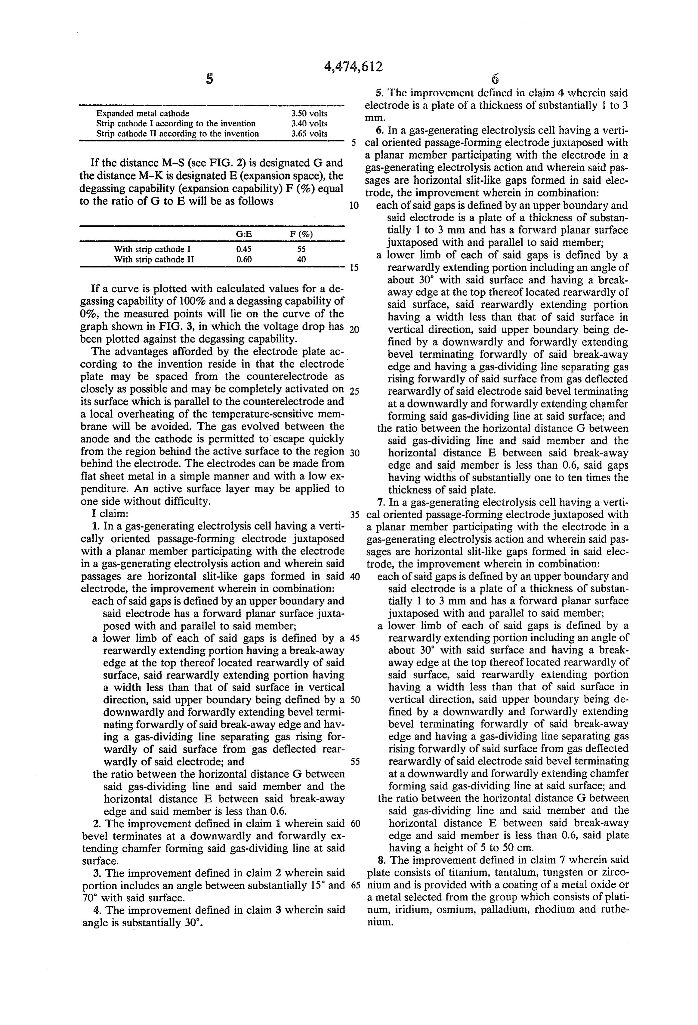
one side without difficulty. 7. In a gas-generating electrolysis cell having a verti I claim: 35 cal oriented passage-forming electrode juxtaposed with 1. In a gas-generating electrolysis cell having a verti a planar member participating with the electrode in a cally oriented passage-forming electrode juxtaposed gas-generating electrolysis action and wherein said pas with a planar member participating with the electrode sages are horizontal slit-like gaps formed in said elec in a gas-generating electrolysis action and wherein said trode, the improvement wherein in combination: passages are horizontal slit-like gaps formed in said 40 each of said gaps is defined by an upper boundary and electrode, the improvement wherein in combination: said electrode is a plate of a thickness of substan each of said gaps is defined by an upper boundary and tially 1 to 3 mm and has a forward planar surface said electrode has a forward planar surface juxta juxtaposed with and parallel to said member; posed with and parallel to said member; a lower limb of each of said gaps is defined by a a lower limb of each of said gaps is defined by a 45 rearwardly extending portion including an angle of rearwardly extending portion having a break-away about 30 with said surface and having a break edge at the top thereof located rearwardly of said away edge at the top thereof located rearwardly of surface, said rearwardly extending portion having said surface, said rearwardly extending portion a width less than that of said surface in vertical having a width less than that of said surface in direction, said upper boundary being defined by a 50 vertical direction, said upper boundary being de downwardly and forwardly extending bevel termi fined by a downwardly and forwardly extending nating forwardly of said break-away edge and hav bevel terminating forwardly of said break-away ing a gas-dividing line separating gas rising for edge and having a gas-dividing line separating gas wardly of said surface from gas deflected rear rising forwardly of said surface from gas deflected wardly of said electrode; and 55 rearwardly of said electrode said bevel terminating the ratio between the horizontal distance G between at a downwardly and forwardly extending chamfer said gas-dividing line and said member and the forming said gas-dividing line at said surface; and horizontal distance E between said break-away the ratio between the horizontal distance G between edge and said member is less than 0.6. said gas-dividing line and said member and the 2. The improvement defined in claim 1 wherein said 60 horizontal distance E between said break-away bevel terminates at a downwardly and forwardly ex edge and said member is less than 0.6, said plate tending chamfer forming said gas-dividing line at said having a height of 5 to 50 cm. surface. 8. The improvement defined in claim 7 wherein said 3. The improvement defined in claim 2 wherein said plate consists of titanium, tantalum, tungsten or zirco portion includes an angle between substantially 15 and 65 nium and is provided with a coating of a metal oxide or 70 with said surface. a metal selected from the group which consists of plati 4. The improvement defined in claim 3 wherein said num, iridium, osmium, palladium, rhodium and ruthe angle is substantially 30'. nium.
Page 7
9. The improvement defined in claim 7 wherein said 31. In an assembly for use in gas-forming electrolyz electrode consists of steel, nickel or an alloy thereof, ers, particularly membrane electrolyzers, comprising a 10. In a vertically extending plate electrode for gas vertically extending plate electrode, a counterelectrode forming electrolyzers, particularly membrane electro and a membrane between the plate electrode and the lyzers, comprising electrode plates which are divided counterelectrode, wherein the plate electrode is divided into horizontal strips having an active electrode surface, into horizontal strips having an active electrode surface which strips throughout their active electrode surface saidfacing the counterelectrode, said strips being parallel to are parallel to a counterelectrode and have the smallest counterelectrode and having the smallest possible possible distance therefrom whereas the top portion of 1.O distance therefrom throughout their active surface area each of said strips extends away from the counterelec tends awayoffrom and each said strips having a top portion which ex trode and defines a gas escape path, the improvement escape path, the the counterelectrode and defines a gas improvement in that the ratio of the wherein the ratio of the distance G between the coun distance G between the counterelectrode or membrane terelectrode or membrane and a gas-dividing line S at a and a gas-dividing line S at the lower edge of each lower edge of each electrode strip to the distance E 15 electrode strip to the distance E between the counter between the counterelectrode or membrane and a electrode or membrane and a breakaway edge K of an breakaway edge K of an angled portion defining gas angled portion defining the gas escape path corresponds escape path corresponds to a value F of the gassing to a value F of the degassing capability below 0.6, capability below 0.6, : k : st
Page 8
REEXAMINATION CERTIFICATE (982nd)
United States Patent (19) (1) B1 4,474,612 Lohrberg 45 Certificate Issued Jan. 3, 1989 (54) VERTICALLY EXTENDING PLATE (56) References Cited ELECTRODE FOR GAS-FORMING FOREIGN PATENT DOCUMENTS
ELECTROLYZERS
(75 Inventor: Karl Lohrberg, Heusenstamm, Fed. 102853 2/1953 Fiance . Rep. of Germany 57-164990 10/1982 Japan.
(73) Assignee: Metallgesellschaft Aktiengesellschaft,
Frankfurt am Main, Fed. Rep. of Primary Examiner-John F. Niebling
Germany (57 ABSTRACT
Reexamination Request: In gas-forming electrolyzers, particularly membrane No. 90/001282, Jul. 7, 1987 electrolyzers having vertically extending plate elec trodes, each electrode plate is divided into horizontal
Reexamination Certificate for: strips and the entire active electrode surface is parallel Patent No.: 4,474,612 to the counterelectrode and spaced from it as closely as Issued: . Oct. 2, 1984 possible. The top portions of each of the horizontal Appl. No.: 520,068 strips into which the electrode is divided define gas Filed: Aug. 3, 1983 escape paths and extend away from the counterelec trode. To improve the degassing of the electrolyte the (30) Foreign Application Priority Data ratio of the distance G between the counterelectrode or Aug. 3, 1982 (DE) Fed. Rep. of Germany ....... 3228884 membrane and the gas-defining line S at the lower edge of each electrode strip to the distance E between the 5ll Int. Cl." ......................... C25B 9/00; C25B 11/03 counterelectrode or membrane and the breakaway edge (52) U.S.C. .................................... 204/252; 204/283; K of the angled portion defining the gas escape path 204/284 corresponds to a degassing capability F which is lower 58) Field of Search ................ 204/252,283, 284, 292 than 0.6.
Page 9
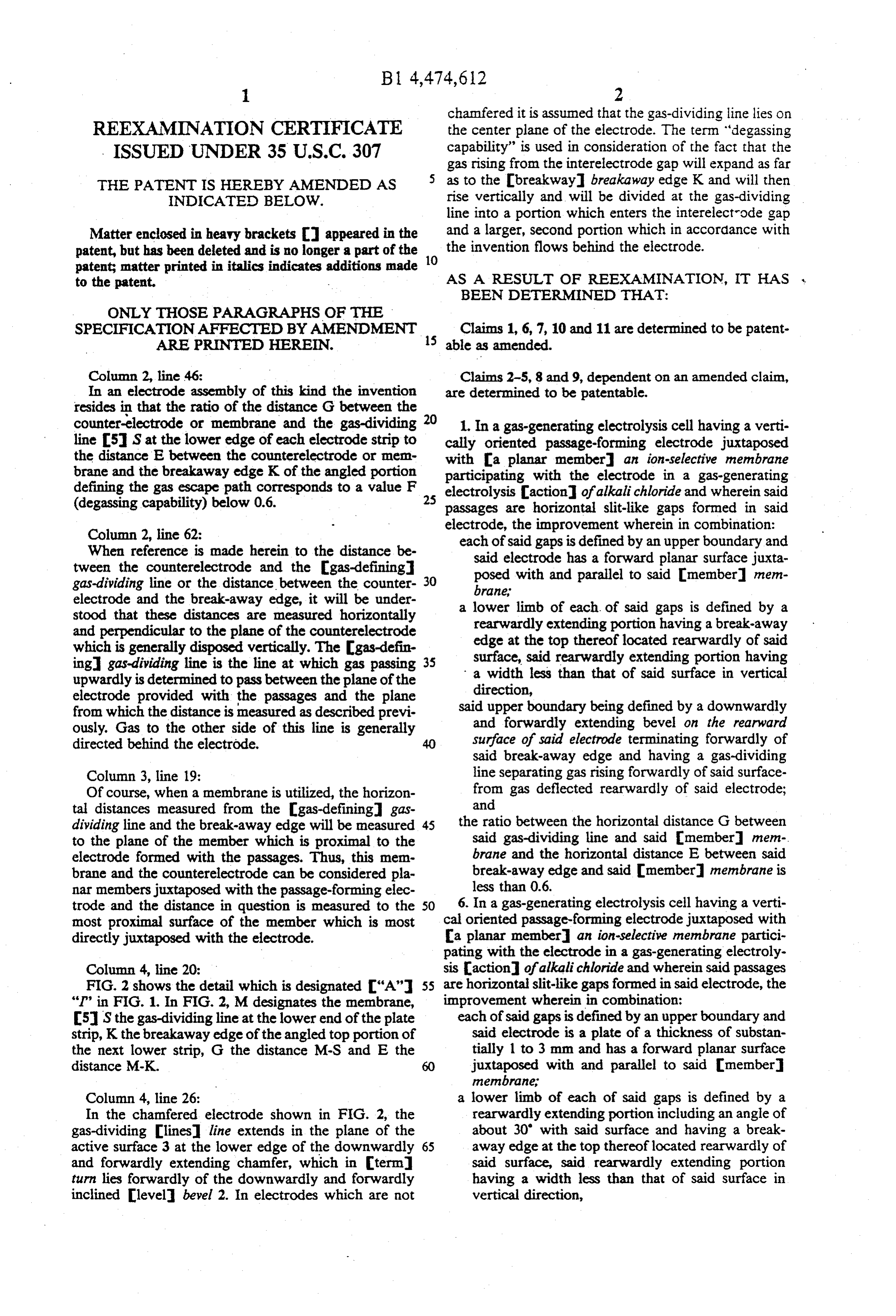
chamfered it is assumed that the gas-dividing line lies on
REEXAMINATION CERTIFICATE the center plane of the electrode. The term “degassing ISSUED UNDER 35 U.S.C. 307 capability” is used in consideration of the fact that the gas rising from the interelectrode gap will expand as far
THE PATENT IS HEREBY AMENDED AS as to the breakway breakaway edge K and will then INDICATE) BELOW. rise vertically and will be divided at the gas-dividing line into a portion which enters the interelectrode gap
Matter enclosed in heavy brackets appeared in the and a larger, second portion which in accordance with patent, but has been deleted and is no longer a part of the the invention flows behind the electrode. patent matter printed in italics indicates additions made 10 to the patent. AS A RESULT OF REEXAMINATION, IT HAS
BEEN DETERMINED THAT:
ONLY THOSE PARAGRAPHS OF THE
SPECIFICATIONAFFECTED BY AMENDMENT Claims 1, 6, 7, 10 and 11 are determined to be patent ARE PRINTED HEREN. 15 able as amended.
Column 2, line 46: Claims 2-5, 8 and 9, dependent on an amended claim, In an electrode assembly of this kind the invention are determined to be patentable. resides in that the ratio of the distance G between the counter-electrode or membrane and the gas-dividing 20 1. In a gas-generating electrolysis cell having a verti line 5 S at the lower edge of each electrode strip to cally oriented passage-forming electrode juxtaposed the distance E between the counterellectrode or mem with a planar member an ion-selective membrane brane and the breakaway edge K of the angled portion participating with the electrode in a gas-generating defining the gas escape path corresponds to a value F electrolysis action of alkali chloride and wherein said
passages are horizontal slit-like gaps formed in said
Column 2, line 62:
electrode, the improvement wherein in combination:
When reference is made herein to the distance be each of said gaps is defined by an upper boundary and tween the counterelectrode and the gas-defining said electrode has a forward planar surface juxta gas-dividing line or the distance between the counter- 30 posed with and parallel to said member mem electrode and the break-away edge, it will be under brane stood that these distances are measured horizontally a lower limb of each of said gaps is defined by a and perpendicular to the plane of the counterelectrode rearwardly extending portion having a break-away which is generally disposed vertically. The gas-defin edge at the top thereof located rearwardly of said ing gas-dividing line is the line at which gas passing 35 surface, said rearwardly extending portion having upwardly is determined to pass between the plane of the a width less than that of said surface in vertical electrode provided with the passages and the plane direction, from which the distance is measured as described previ said upper boundary being defined by a downwardly ously. Gas to the other side of this line is generally and forwardly extending bevel on the rearward directed behind the electrode. surface of said electrode terminating forwardly of said break-away edge and having a gas-dividing
Column 3, line 19: line separating gas rising forwardly of said surface Of course, when a membrane is utilized, the horizon from gas deflected rearwardly of said electrode; tal distances measured from the gas-defining gas and dividing line and the break-away edge will be measured 45 the ratio between the horizontal distance G between to the plane of the member which is proximal to the said gas-dividing line and said member mem electrode formed with the passages. Thus, this mem brane and the horizontal distance E between said brane and the counterelectrode can be considered pla break-away edge and said member membrane is nar members juxtaposed with the passage-forming elec less than 0.6.
trode and the distance in question is measured to the 50 6. In a gas-generating electrolysis cell having a verti most proximal surface of the member which is most cal oriented passage-forming electrode juxtaposed with directly juxtaposed with the electrode. a planar member an ion-selective membrane partici pating with the electrode in a gas-generating electroly
Column 4, line 20: sis action of alkali chloride and wherein said passages FIG. 2 shows the detail which is designated "A" 55 are horizontal slit-like gaps formed in said electrode, the "I" in FIG. 1. In FIG. 2, M designates the membrane, improvement wherein in combination:
SS the gas-dividing line at the lower end of the plate each of said gaps is defined by an upper boundary and strip, K the breakaway edge of the angled top portion of said electrode is a plate of a thickness of substan the next lower strip, G the distance M-S and E the tially 1 to 3 mm and has a forward planar surface distance M-K. 60 juxtaposed with and parallel to said member membrane
Column 4, line 26: a lower limb of each of said gaps is defined by a In the chamfered electrode shown in FIG. 2, the rearwardly extending portion including an angle of gas-dividing lines line extends in the plane of the about 30 with said surface and having a break active surface 3 at the lower edge of the downwardly 65 away edge at the top thereof located rearwardly of and forwardly extending chamfer, which in term said surface, said rearwardly extending portion turn lies forwardly of the downwardly and forwardly having a width less than that of said surface in inclined level bevel 2. In electrodes which are not vertical direction,
Page 10
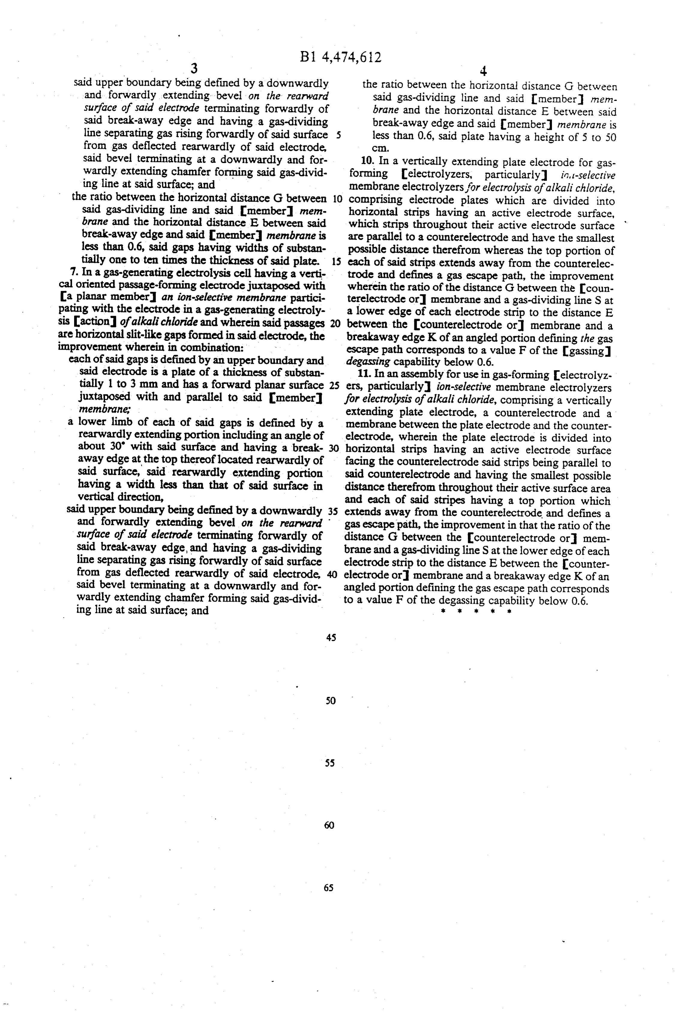
said upper boundary being defined by a downwardly the ratio between the horizontal distance G between and forwardly extending bevel on the rearward said gas-dividing line and said Innenber men surface of said electrode terminating forwardly of brane and the horizontal distance E between said said break-away edge and having a gas-dividing break-away edge and said member membrane is line separating gas rising forwardly of said surface 5 less than 0.6, said plate having a height of 5 to 50 from gas deflected rearwardly of said electrode, C.
said bevel terminating at a downwardly and for 10. In a vertically extending plate electrode for gas wardly extending chamfer forming said gas-divid forming electrolyzers, particularly it, t-selective ing line at said surface; and membrane electrolyzers for electrolysis of alkali chloride, the ratio between the horizontal distance G between 10 comprising electrode plates which are divided into said gas-dividing line and said member mem horizontal strips having an active electrode surface, brane and the horizontal distance E between said which strips throughout their active electrode surface break-away edge and said member membrane is are parallel to a counterelectrode and have the smallest less than 0.6, said gaps having widths of substan possible distance therefrom whereas the top portion of tially one to ten times the thickness of said plate. 15 each of said strips extends away from the counterelec 7. In a gas-generating electrolysis cell having a verti trode and defines a gas escape path, the improvement cal oriented passage-forming electrode juxtaposed with wherein the ratio of the distance G between the coun a planar member an ion-selective membrane partici pating with the electrode in a gas-generating electroly aterelectrode or membrane and a gas-dividing line S at lower edge of each electrode strip to the distance E sis action of alkali chloride and wherein said passages 20 between the counterelectrode or membrane and a are horizontal slit-like gaps formed in said electrode, the breakaway edge Kof an angled portion defining the gas improvement wherein in combination: w escape path corresponds to a value F of the gassing each of said gaps is defined by an upper boundary and degassing capability below 0.6.
said electrode is a plate of a thickness of substan 11. In an assembly for use in gas-forming electrolyz tially 1 to 3 mm and has a forward planar surface 25 ers, particularly ion-selective membrane electrolyzers juxtaposed with and parallel to said member for electrolysis of alkali chloride, comprising a vertically membrane extending plate electrode, a counterelectrode and a lower limb of each of said gaps is defined by a membrane between the plate electrode and the counter rearwardly extending portion including an angle of electrode, wherein the plate electrode is divided into about 30' with said surface and having a break 30 horizontal strips having an active electrode surface away edge at the top thereoflocated rearwardly of facing the counterelectrode said strips being parallel to said surface, said rearwardly extending portion said counterelectrode and having the smallest possible having a width less than that of said surface in distance therefrom throughout their active surface area vertical direction, and each of said stripes having a top portion which said upper boundary being defined by a downwardly 35 extends away from the counterelectrode and defines a and forwardly extending bevel on the rearward gas escape path, the improvement in that the ratio of the surface of said electrode terminating forwardly of distance G between the counterelectrode or mem said break-away edge, and having a gas-dividing brane and a gas-dividing line S at the lower edge of each line separating gas rising forwardly of said surface electrode strip to the distance E between the counter from gas deflected rearwardly of said electrode, 40 electrode or membrane and a breakaway edge K of an said bevel terminating at a downwardly and for angled portion defining the gas escape path corresponds wardly extending chamfer forming said gas-divid to a value F of the degassing capability below 0.6. ing line at said surface; and : xx k s
Provenance
- Collection
- Cited prior art
- Original PDF
- patentimages.storage.googleapis.com →
- Filed
- 1983-08-03
- Pages
- 10
- Method
- pdftotext (the PDF's own text layer) + pdftoppm 300dpi page scans
- Source
- Google Patents bibliographic record
- Granted
- 1984-10-02
- Inventors
- Karl Lohrberg; Metallgesellschaft AG
- Transcribed from
- patentimages.storage.googleapis.com →