patent · US2669873
Flowmeter
23 February 1954
Page 1
Drawing sheet — no readable text.
Page 2
Patented Feb. 23, 1954
UNITED STATES PATENT OFFICE
FLOWMETER
George F. Gardner, Scotia, and Theodore A. Rich,
Schenectady, N.Y., assignors to General Elec tric Company, a corporation of New York
Application March 22, 1950, Serial No. 151,141
This invention relates to apparatus for meas 2 having an orifice. 3, as shown. As fluid flows tiring the flow of fluids.
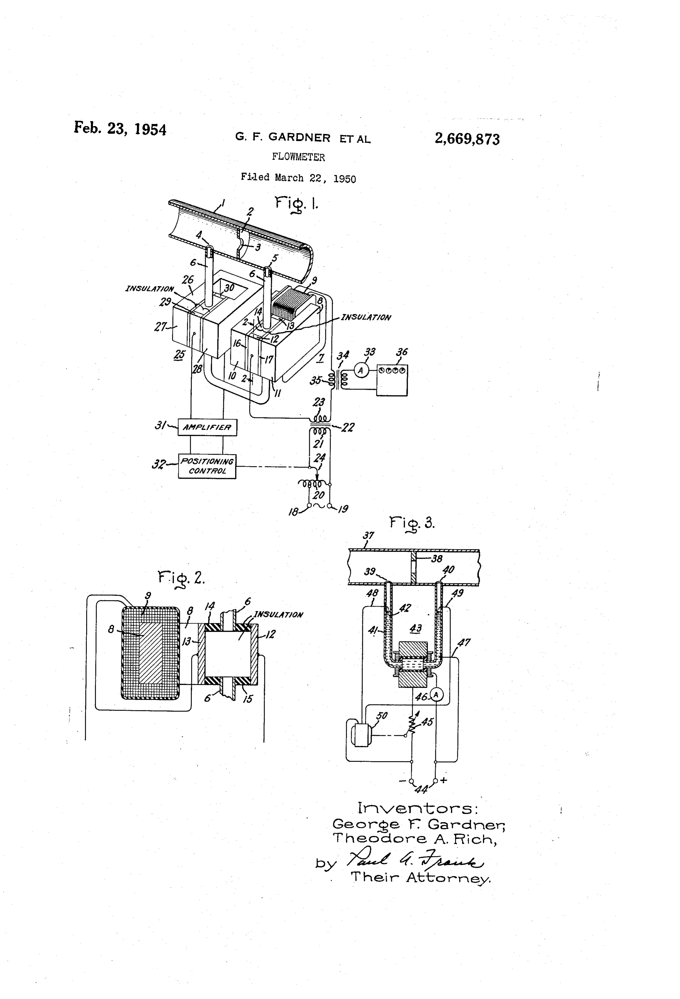
... An object of the invention is to provide an through the conduit, the constricting means pro improved remote-indicating fow heter which in duces a differential pressure between points 4 volves no moving parts and no empirical correc and 5 which is substantially proportional to the tion devices. Square of the fluid flow rate. Another object is to provide an innproved flow A tube 6 defines a branch paSSageWay between meter in which the liquid may be confined in an points 4 and 5. The differential pressure between all-metal, all-welded container, thereby provid these two points tends to produce fluid flow ing increased safety and reliability in measuring it tube S. is the through branch passageway. Connected to an electromagnetic pump 7 which pro the filow rate of corrosive or otherwise dangerols duces a differential pressure through the fluid fluids.
Other objects and advantages will appear as opposes the within branch passageway. This pressure the differential pressure between points the description proceeds.
4 and 5, and thus substantially prevents, fluid
In the improved low meter, a differential pres- 5 flow
Sure having a magnitude related to... the flow late through tube 6, as is hereinafter more fully explained.
is produced between two points along the length Referring now to Figs, 1 and 2, the electro Of a conduit. Ol' flow line by conventional flow magnetic pump may comprise an electromagnet constricting means. A branch passageway con having a core member 8 and a winding 9. Be nects these two points; and the pressure diffe ) tween the pole pieces 0 and of this electro ential tends to produce fluid flow through this magnet, there is a chamber defined by walls. Com passageway. An opposing differential pressure of prising metal electrodes 2 and 3 and insulating adjustable magnitude is provided by an electro in embers 4, 5, 6 and , as shown. Tube S magnetic pump connected to the passageway. is connected to this chamber, so that fluid. Within Flow-responsive detecting means and a control is the mechanism operate in response to any fluid flow fiuidtube also fills the chamber, and SO that any flowing through the tube also flows through through the passageway to adjust the amount of electric current applied to the electromagnetic the chamber. The insulating members need not be electrical insulators in an absolute Sense. It punp, and thereby control the differential pres is sufficient that their electrical conductivity be sure produced by the pump, to prevent substan- 30 adequately low with respect to the electrical con tial flow of fluid through the passageway. ductivity of the fluid that a substantial portion The electromagnetic pumps referred to in this of the electric current which passes between specification are of the type in which 3, magnetic electrodes 2 and 3, as hereinafter explained, field is provided transversely through a passage. passes through the fluid rather than through the way containing an electrically conductive fuid, 35 side walls of the chamber. The insulating mem and an electric surrent is passed through tie bers may, for example, be constructed of low fluid perpendicular to the magnetic field. This conductivity metal, or other suitable material. produces a differential pressure in the fluid which Alternating current from a suitable source is is proportional to the product of magnetic field applied, through terminals 8 and 9 and auto intensity rent.
and the amount
of such electric cur- 40 transformer 20, to the primary winding 2 of a
The features of this invention which are be transformer 22, which has a secondary winding lieved to be novel and patentable are pointed out 23. One terminal of Secondary Winding 23 is ir claims which form a part of this specification. nal connected to electrode 2, and the other termi of the Secondary winding is connected
For a better understanding of the invention, erence, is made in the following description to ref- as through winding 9 to electrode 3. Electric cur the accompanying drawing, in which Fig. 1 is a rent flows through secondary winding 23 to elec schematic diagram of an improved flow meter; trode 2, through the conductive fluid to elec trode 3, through winding 9, and then back to
Fig. 2 is a section along line. 2-2 of Fig. 1; and secondary winding 23, The current through Fig. 3 is a schematic proved flow meter. diagram of another im- so winding 9 provides a magnetic field between pole Referring now to Fig. i., an electrically con pieces 0 and perpendicular to the electric ductive fuid to be metered may flow from left current flow through the fluid. This creates a to right through conduit . In the conduit there differential pressure in the fluid within tube 6 is a flow constricting means, which may be a disc 55 which opposes the differential pressure between points 4 and 5. The magnetic field provided is
Page 3
3 42, such as mercury. An electromagnetic pump proportional to the amount of current; and, since 43 is connected to tube 4 to provide a differential the amount of differential pressure produced is pressure through fluid 42 in opposition to the proportional to the product of current and mag differential pressure between points 39 and 40. netic field intensity, the differential pressile is This pump may be operated with alternating or substantially proportional to the Square of the direct current supplied through terminals 44. The amount of current supplied to the pump. The amount of this current is controlled by a vari annount of this current, and, hence, the amount able series resistor 45, and is measured by an of differential pressure provided, may be con trolled by adjusting a tap 24 on autotrans () ammeter 46.
A first electrode 4 is in electrical contact with former 20. conductive fluid 42. Second and third electrodes A flow detectol 25 is coilnected to tube 6 in 48 and 49 are positioned within tube 4 ad responsive relation to fuid flow therethrough. jacent to respective ends of the portion thereof Flow detector 25 may conprise a permanent which contains the conductive fluid, as shown. magnet 26, having pole pieces 27 and 28, which If the differential pressure provided by pump rovides a magnetic field transversely through 43 is not sufficiently great to counteract the dif the conductive fluid. A filid chamber having ferential pressure between points 39 and 40, fiuid electrodes 29 and 38 is provided between pole 42 tends to flow through the tube and rises in pieces 2 and 23, which may be of the same con the right-hand leg of tube 4 until it contacts struction as tine electromagnetic pump fluid electrode 49. This completes an electric circuit chamber. Any flow of electrically conductive through reversible electric motor 59. which oper fluid through tube 6 produces a Woltage gradient ates to reduce the resistance of resistor 45 and through the fluid perpendicular to the direction supply more current to pump 43. The adjusting of flow and also perpendicular to the direction action continues until the two opposed differen of the magnetic field between pole pieces 2 and tial pressures are equal, whereupon fluid 42 re 28. This provides a voltage between electrodes turns to the position shown in the drawing, there 29 and 38 which is substantially proportional to by opening the electric circuit. If the differential the late of iuid flow through tube 6, and which pressure supplied by pump 43 is too great, the has a polarity determined by the direction of liquid rises in the left-hand leg of tube 4 and Such flow. nakes contact with electrode 48. This closes an The voltage between electrodes 29 and 33 is electric circuit which operates motor 50 in the amplified by an annplifier 3. The aimplified volt reverse direction to reduce the current supplied age operates conventional positioning-control to pump 43.
apparatus 32 to adjust the position of tap 24, and thereby controls the amount of current supplied tionHaving described the principle of this inven and the best mode in which we have con to pump l. In this manner, the differential templated applying that principle, We wish it to pressure provided by pump is kept Substantially be understood that the apparatus described is at the collect value exactly to counteract the illustrative only, and that other means can be differential pressure between points d and 5, which substantially prevents the fow of fluid employed without departing from the true scope of the invention.
through tube 6. What we claim as new and desire to secure by The amount of electric Cullent Supplied to Letters Patent of the United States is: pump to prevent fluid flow through tube 6 is related to the rate of fluid flow through Conduit i. In combination, means defining a fluid pas f. This relation is a linear One, because the sageway to contain an electrically conductive differential pressure between points 4 and 3 is fluid, an electromagnetic pump formed by an substantially proportional to the Square of the electromagnet comprising a core ninenbel' having extensions therefronn defining a pair of pole flow rate, and the differential pressure provided pieces that surround a portion of the passage by pump 7 is substantially proportional to the Way, a pair of current electrodes disposed on op square of the electric current supplied to the pump. The linear relation is advantageous be 50 posite sides of said portion of the passageway and contacting the fluid flowing therethrough, cause it pernits easy automatic integration of and a current Supply Winding Surrounding said flow rate values without the use of empirical correction devices. Core member, the electromagnetic pump thus The amount of cul'rent Supplied to pump is comprised serving to provide a differential fluid indicated by an amneter 33 connected to an in 5 preSSure
ply through said paSSageway, means to sup electric current to said current supply wind strument tiansformer 34, which has a primary
Winding 35 electrically connected in series with ing and said current electrodes, the amount of winding 9, as shown. The scale of the ammeter such differential pressure being related to the may be calibrated to read directly in flow rate amount of Such current, lineans responsive to units. An integrating netter, Such as ampere 60 fluid flow within said passageway for adjusting hour meter 36, may also be employed to indicate the value of Such current to control the differ the total flow of fluid through conduit f over a ential pressure provided by said pump Substan period of tinne. It will be appreciated that other tially to prevent such flow, and indicating instru means, such as recorders or control apparatus, ment means coupled to said current supply can be employed in lieu of, or in conbination means for deriving an indication of the current with, ammeter 33 and annpere hour meter 36. flow.
A flow meter for measuring the flow of elec 2. A flow meter comprising a conduit, means trically nonconductive fluids is illustrated in Fig. defining a fluid passageway to contain an elec 3. The nonconductive fluid may flow from left trically conductive fluid connected at its ends to right thirough a conduit 3 in which there is a to respective points along the length of said flow constricting neans 38. This fluid flow cle Conduit, flow-constricting means within Said con ates a pressure differential between points 39 duit for producing a differential fluid pressure and 40. A tube 4 defines a blanch passage between the ends of said passageway, such pres way between points 39 and 40. A portion of this Sure being related to the rate of fluid flow through tube is filled with an electrically conductive fluid Said conduit, an electromagnetic pump formed
Page 4
by an electromagnet comprising a core member erated by said flow detector for adjusting the having extensions therefrom defining a pair of value of such current to control the differential pole pieces that surround a portion of the pass pressure provided by said pump substantially to 'sageway, a pair of current electrodes disposed prevent such flow, and indicating instrument on opposite sides of said portion of the passage 5 means coupled to said current supply means for Way and contacting the fluid flowing theres through, and a current supply winding surround deriving an indication of the current flow. 5. In combination, means defining a fluid pas ing said core member, the electromagnetic pump sageway, an electrically conductive fluid filling a thus comprised serving to provide a differential portion of such passageway, an electromagnetic fluid pressure through said passageway in op ) pump, formed by an electromagnet comprising position to the differential pressure produced by fluid flow through the conduit, means to supply fining amember a core having extensions therefrom de pair of pole pieces that surround a por electric current to said current supply winding tion of the passageway, a pair of current elec and said current electrodes, the amount of dif trodes disposed. On opposite sides of Said por ferential pressure provided by the pump being tion of the passageway and contacting the fluid related to the amount of Such current, means flowing therethrough, and a current supply responsive to fluid flow within said, passageway winding surrounding said core member, the for adjusting the value of such current to con electromagnetic pump thus comprised serving to trol the "differential pressure provided by: said provide pump Substantially to prevent Such flow, and in 20 means toa supply differential pressure within said fluid, electric current to said current dicating instrument means coupled to said curr supply winding and said current electrodes, the rent supply means for deriving an indication of amount of such differential pressure being re
lated to the amount of such current, a first elec 3. In combination, means defining a fluid pas trode sageway to contain an electrically. Conductive 55 Ond and in electrical contact with said fluid, sec fluid, an electromagnetic pump formed by an adjacent third electrodes within said passageway to respective ends of the portion there electromagnet comprising a core member hav of which contains the conductive fluid, so that ing extensions therefrom defining a pair of pole flow of said fluid in either direction completes pieces that surround a portion of the passage an electric circuit between Said first electrode way, a pair of current electrodes disposed on op i and said second or third electrode selectively, posite sides of said portion of the passageway -control means operated by completion of such and contacting the fluid flowing therethrough, and a current supply winding surrounding said circuit for adjusting the value of current sup plied to the pump substantially to prevent flow core member, the electromagnetic pump; thus of said fluid, and indicating instrument means comprised serving to provide a differential fluid Coupled to said current supply means for deriv pressures through said passageway, means to ing an indication of the current flow, ..., supply electric current to said current supply 6. A flow meter comprising a conduit, means winding and said current electrodes, the amount defining a fluid passageway connected at its ends of such differential pressure being related to the to respective points, along the length of said amount of such current, an electromagnetic flow 40 Conduit, flow-constricting means within said meter connected in responsive relation to fluid conduit for producing a differential fluids pres flow within said passageway, and control means "Sure between the ends of said passageway, such operated by said flow meter for adjusting the preSSure being related to the rate of fluid flow value of such current to control the differential pressure provided by said pump substantially to through said conduit, an electrically, conductive fluid filling a portion of said passageway, an prevent such flow, and indicating instrument electromagnetic pump formed by an electromag means coupled to said current Supply means for net comprising a core member having extensions deriving an indication of the current flow. therefrom defining a pair of pole pieces that 4. A flow meter comprising a conduit, means Surround a portion of the passageway, a pair of defining a fluid passageway to contain an elec Current electrodes disposed on opposite sides trically conductive fluid connected at its ends to of said portion of the passageway and contacting respective points along the length of said con the fluid flowing therethrough, and a current duit, flow-constricting means within said con supply winding surrounding said core member, duit for producing a differential fluid pressure the electromagnetic pump thus comprised serving between the ends of said passageway, such pres to provide a differential fluid pressure in op sure being related to the rate of fluid flow through position to the differential pressure produced by said conduit, an electromagnetic pump formed fluid flow through the conduit, means to supply by an electromagnet comprising a core member electric current to said current supply winding shaving extensions therefrom defining a pair of and said current electrodes, the amount of differ. pole-pieces that surround a portion of the pas ential pressure provided by the pump being re sageway, a pair of current electrodes disposed lated to the amount of such current, a first elec on opposite sides of said portion of the passage trode, in electrical contact with said fluid, second way and contacting the fluid flowing there and third electrodes within said passageway ad through, and a current supply winding sur jacent to respective ends of the portion thereof rounding said core member, the electromagnetic pump thus comprised serving to provide a dif which contains the conductive fluid, so that flow ferential fluid pressure in opposition to the dif of said fluid in either direction completes an elec ferential pressure produced by fluid flow through tric circuit between said first electrode and said the conduit, means to supply electric current to Second or said third electrode selectively, control said current supply winding and said current means operated by completion of such circuit for adjusting the value of current supplied to the electrodes, the amount of differential pressure pump substantially to prevent flow of said fluid, provided by the pump being related to the and indicating instrument means coupled to said amount of such current, an electromagnetic flow current supply means for deriving an indication detector connected in responsive relation to fluid Of the current fow. - flow within said passageway, control means op 7. In combination, means defining a fluid pas
Page 5
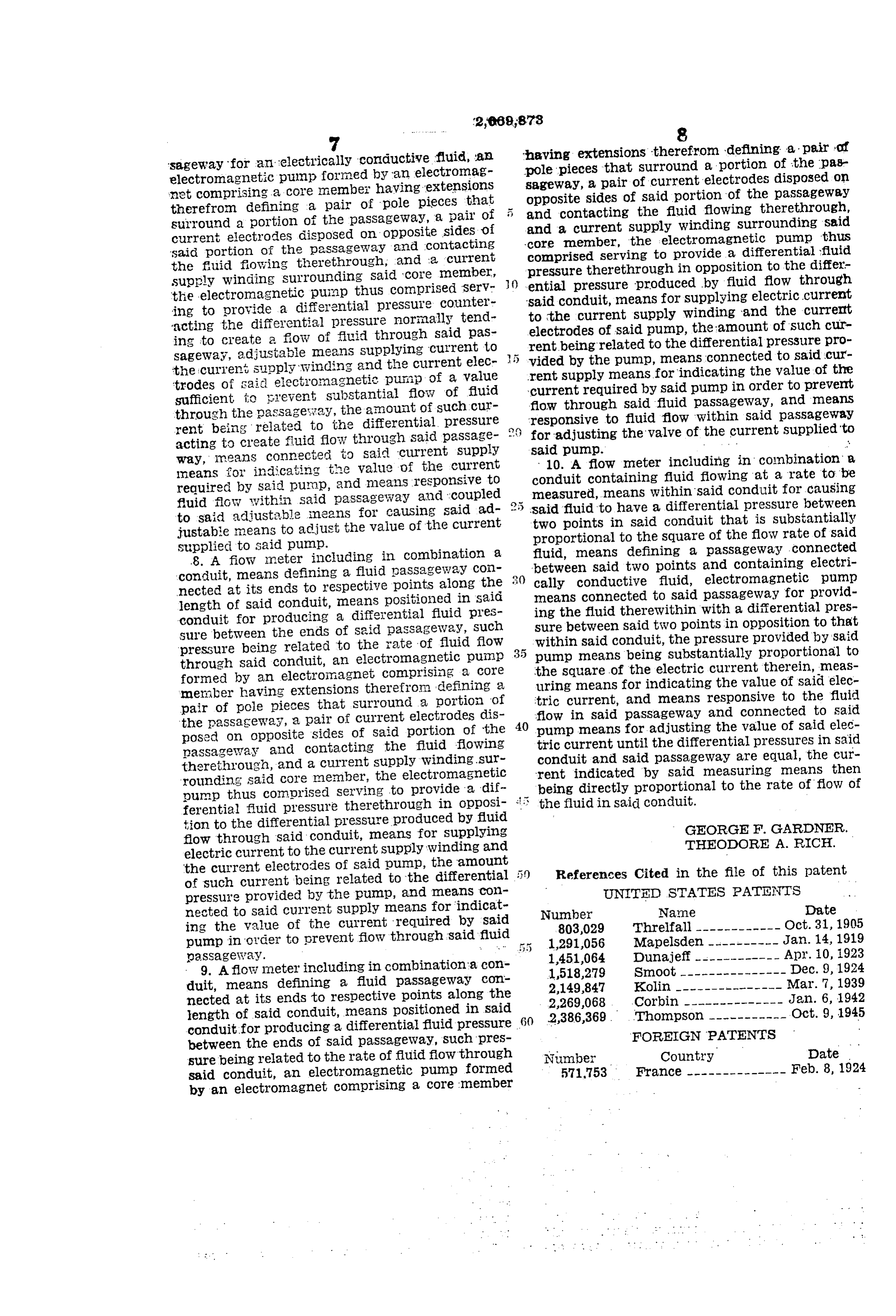
having extensions therefrom defining a pair of 'sageway for an electrically conductive fluid, an pole pieces that surround a portion of the pas electromagnetic pump formed by an electronag sageway, a pair of current electrodes disposed on net comprising a core member having 'extensions opposite sides of said portion of the passageway therefrom defining a pair of pole pieces that 5 and surround a portion of the passageway, a pair of and acontacting current the fluid flowing therethrough,
Supply winding Surrounding said current electrodes disposed on opposite sides of core member, the selectromagnetic pump thus said portion of the passageway and contacting comprised serving to provide a differential fluid the fluid flowing therethrough, and a current supply winding surrounding said core member, () pressure ential therethrough in opposition to the differ pressure produced by fluid flow through the electromagnetic punp thus comprised Serv said conduit, means for Supplying electric current ing to provide a differential pressure counter to the current supply acting the differential pressure norinally tend electrodes of said pump,winding the and the current amount of such cur ing to create a flow of fluid through said pas rent being related to the differential pressure sageway, adjustable means supplying current to vided by the pump, means connected to said pro cur the current supply winding and the current elec rent Supply means for indicating the value of the trodes of said electromagnetic pump of a value current required by said pump in order to prevent sufficient to grevent substantial flow of fluid flow through Said fluid passageway, and means through the passageway, the amount of such cur rent being related to the differential preSSure e responsive for adjusting to fluid flow within said passageway the valve of the current supplied to acting to create fluid flow through Said passage way, means connected to said current Supply Said10.pump. - A flow meter including in combination a
neans for indicating the value of the current required by said pump, and means responsive to conduit measured, containing fluid flowing at a rate to be means within Said conduit for causing fluid flow within said passageway and coupled to said adjustable means for causing said ad 2 5 Said fluid to have a differential pressure between justable means to adjust the value of the current two points in Said conduit that is substantially proportional to the square of the flow rate of said
Supplied to said pump. fluid, means defining a passageway connected 8. A fiow meter including in combination a between said two points and containing electri conduit, means defining a fluid passageway COin cally conductive fluid, electromagnetic pump nected at its ends to respective points along the means connected to said passageway for provid length of said conduit, means positioned in said ing the fluid therewithin with a differential pres conduit for producing a differential fluid ples Sure between Said two points in opposition to that sure between the ends of said passageway, Such within said conduit, the pressure provided by said pressure being related to the rate of fluid flow pump means being Substantially proportional to through said conduit, an electromagnetic pump the Square of the electric current therein, meas formed by an electromagnet comprisiing a COre uring means for indicating the value of said elec member having extensions therefron defining a pair of pole pieces that surround a portion of tric current, and means responsive to the fluid the passageway, a pair of current electrodes dis 40 flow in Said passageway and connected to said pump means for adjusting the value of Said elec posed on opposite sides of said portion of the passageway and contacting the fluid flowing tric current until the differential pressures in said therethrough, and a current supply winding sur conduit and Said passageway are equal, the cur rounding said core member, the electromagnetic beingrent indicated by Said measuring means then pump thus comprised serving to provide a dif directly proportional to the rate of flow of ferential fluid pressure therethrough in opposi- 5 the fluid in said conduit.
tion to the differential pressure produced by fluid GEORGE. F. GARDNER flow through said conduit, means for supplying THEODORE. A. RICH. electric current to the current supply winding and the current electrodes of said pump, the amount References Cited in the file of this patent of Such current being related to the differential :
pressure provided by the pump, and neans Coll UNITED STATES PATENTS nected to said current Supply means for indicat Number Name Date . ing the value of the current required by said 803,029 Threlfall ------------ Oct. 31, 1905 pump in order to prevent flow through said fluid 1291,056 Mapelsden ---------- Jan. 14, 1919 passageway. . . . 1,451,064 Dunajeff ------------ Apr. 10, 1923 9. A flow Imeter including in combination a con 1518,279 Smoot --------------- Dec. 9, 1924 duit, means defining a fluid passageway con 2,149,847 Kolin --------------- Mar. 7, 1939 nected at its ends to respective points along the 2,269,068 Corbin -------------- Jan. 6, 1942 length of said conduit, means positioned in said 2,386,369. Thompson ---------- Oct. 9, 1945 conduit for producing a differential fluid pressure 60 between the ends of Said passageway, such pres FOREIGN PATENTS sure being related to the rate of fluid flow through Number Country Date said conduit, an electromagnetic pump formed 571,753 France -------------- Feb. 8, 1924 by an electromagnet comprising a core member
Provenance
- Collection
- Cited prior art
- Original PDF
- patentimages.storage.googleapis.com →
- Filed
- 1950-03-22
- Pages
- 5
- Method
- pdftotext (the PDF's own text layer) + pdftoppm 300dpi page scans
- Source
- Google Patents bibliographic record
- Granted
- 1954-02-23
- Inventors
- George F Gardner; Theodore A Rich; General Electric Co
- Transcribed from
- patentimages.storage.googleapis.com →