patent · US3518462
Fluid flow control system
30 June 1970
Page 1
Drawing sheet — no readable text.
Page 2
June 30, 1970 T. T. BROWN 3,518,462
FLUID FLOW CONTROL, SYSTEM
Filed Aug. 2l, l967 2 Sheets-Sheet
12 le. -13 7v Z
//OMA576ws2/wo aeeuw
age 41za 22eáa?
Page 3
United States Patent Office 1.
Patented June 30, 1970
turn, usually entails the need for expensive power ampli
FLUID FLOW CONTROL SYSTEM Hence, those concerned with the development and use Thomas Townsend Brown, Santa Monica, Calif., assignor, of electrokinetic apparatus of the aforedescribed type by mesne assignments, to Guidance Technology, Inc. have long recognized the need for improved electrokinetic Filed Aug. 21, 1967, Ser: No. 662,105 apparatus whereby the fluid flow rate and pressure of an
U.S. C. 310-10 13 Claims ionizable dielectric fluid medium can be more efficiently, economically and reliably controlled over a relatively wide range. The present invention fulfills this need.
SUMMARY OF THE INVENTION
Apparatus for producing fluid flow and for selectively Briefly, and in general terms, the present invention pro varying the flow rate and pressure of an ionizable, dielec: vides an electrofluid-dynamic triode wherein a three-elec tric fluid medium. Three spaced apart electrodes are sup trode array of prescribed size, shape, spatial relationship ported in the fluid medium with a high D.C. voltage im 5 and electrical potentials, is used to produce fluid flow and pressed across the two outermost electrodes, the D.C. selectively vary flow rate and pressure in an ionizable, voltage being of sufficient magnitude to produce ioniza dielectric fluid medium.
tion adjacent one electrode of the outermost pair but being Use of the term "dielectric fluid medium' with refer below the voltage level at which arcing, between any of ence to the present invention is deemed to include any and the electrodes would occur. The D.C. electrical potential 20 all suitable dielectric liquids, dielectric gases, and mobile of the third electrode located intermediate the outermost dielectric solids suspended in an appropriate fluid vehicle. electrode pair is varied to alter the shape of the electro- . The electrofluid-dynamic triode includes first and sec static field between the electrodes and thereby vary the ond spaced apart electrodes immersed in the dielectric quiescent fluid flow rate. A relatively low level A.C. elec trical signal may also be applied to the third electrode fluid medium. A third electrode, also immersed in the fluid medium, is physically located in the space between to modulate the fluid flow and pressure whereby a com the first and second electrodes and is spaced apart from bined signal amplifier and electro-acoustic transducer is both of these latter electrodes. The second and third elec provided. .. . . . . . . . trodes have a greater surface area than the first electrode, and the second electrode preferably has a greater surface 30 area than the third electrode. A relatively high D.C. volt
BACKGROUND OF THE INVENTION age is impressed across the first and second electrodes, the This invention relates generally to improvements in magnitude of the impressed voltage being equal to or fluid flow control systems and, more particularly, to a new. greater than the ionization threshold for the first elec and improved flow, control system wherein a relatively trode, but less than the voltage level at which arcing Would occur between any of the three electrode, whereby low level electrical signal input controls or modulates the relative flow between the dielectric fluid medium and the output pressure and flow rate of an ionizable dielectric three-electrode structure is produced. fluid medium. The invention finds particular application The third electrode is a control electrode, and means as a fluid pump and as a combined signal power amplifier are provided for varying and loudspeaker. c. . . .. . . 40 third electrode to vary thetherateelectrical potential of the It has been heretofore proposed that electrohydrody the fluid medium. In this regard,of the flow and pressure of D.C. potential of namic phenomena and electrophoresis be harnessed to the third electrode may be varied to control quiescent or convert electrical energy directly into fluid flow without steady state fluid flow rate or the A.C. potential may be the aid of moving parts. Typical examples of structural varied by modulation to cause no net change in flow rate arrangements suitable for this purpose are disclosed in but to generate pressure waves. If desired, both A.C. and the present applicant's prior U.S. Pats. Nos. 2,949,550 45 D.C. potentials may be varied to simultaneously control and 3,018,394. Both of these patents teach electrokinetic flow. rate and generate. pressure waves. Relatively small apparatus wherein a pair of oppositely charged electrodes of appropriate form are maintained in specified spatial Variations large in control electrode potential yield relatively variations in output flow and pressure. Hence, the relationship and are immersed in a dielectric fluid medi 50 invention is capable of being utilized as a fluid pump, as um to generate a force which moves the dielectric medi um with respect to the pair of electrodes. Hence, the Well a a combined signal amplifier and output pressure apparatus functions as a noiseless fan or pump utilizing transducer.
In presently preferred embodiments, by way of example
and not by way of limitation, additional preamplification
In applicant's U.S. Pat. No. 3,018,394, the electrical 55 of the A.C. modulation signal may be provided, the basic current flow between the pair of electrodes is electrically three-electrode modulated to generate pressure waves in the dielectric configuration may be provided in push fluid medium so that the system can perform as an electro pull versions involving no net fluid flow, the electrodes may be heated and/or coated with various materials to acoustic transducer or loadspeaker. In this regard, a rela tively high level A.C. signal is superimposed upon the 60 improve emissivity, and the electrodes may be fabricated of materials which permit higher operating voltages while
D.C. high voltage bias across the electrode pair to produce simultaneously minimizing the likelihood of arcing be. pressure pulses in the form of compressions and rarefac tween the electrodes. - tions in the fluid medium and thereby generate sound waves. The resultant device may operate either as a load BRIEF DESCRIPTION OF THE DRAWINGS speaker or, conversely, as a microphone.
Unfortunately, while the aforedescribed electrokinetic inventionabove
The and other objects and advantages of the
systems have generally served their purposes, those ap will become apparent from the following more detailed description, when taken in conjunction with the plications calling for electrical modulation or control of accompanying drawings of illustrative embodiments there fluid flow rate have encountered difficulties in that the of, and wherein:
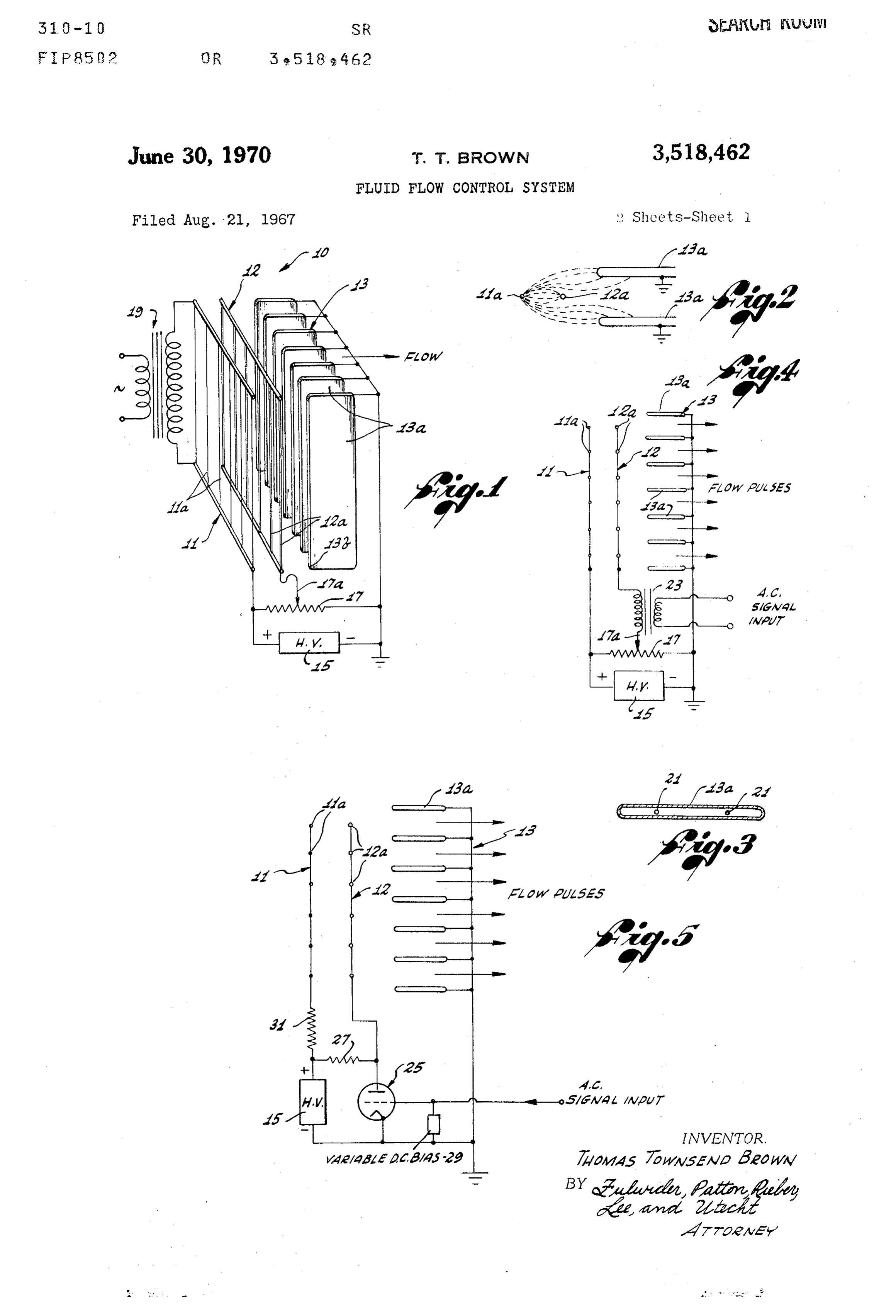
entire D.C. supply current between the electrode pair FIG. 1 is a combined electrical schematic diagram and must be modulated by the control signal. This requires a perspective view of an electrofluid-dynamic triode in ac relatively large amount of control signal energy which, in cordance with the present invention and adapted to selec
Page 4
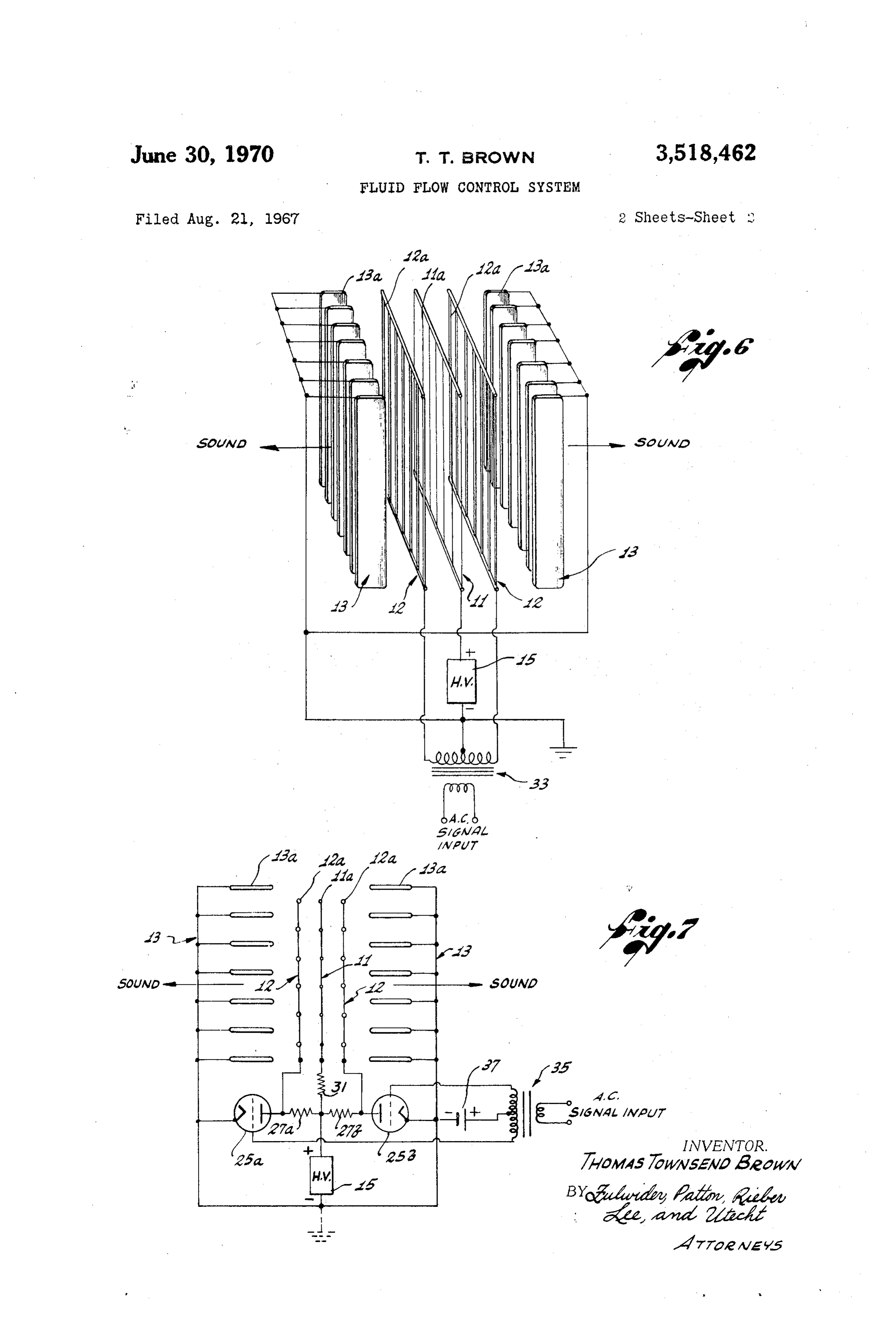
tively vary quiescent flow rate of a dielectric fluid medium; . . . field, i.e., towards the electrode 13 which functions as a FIG. 2 is an enlarged, partial plan view of the elec cathode electrode. - trode array of FIG. 1, illustrating a typical electrostatic Depending upon the system requirements, either the field pattern established by the electrodes; positive or negative side of the power supply 15 may be FIG. 3 is an enlarged, sectional view of one of the elec grounded, or the entire power supply may be floating with trodes of a typical electrofluid-dynamic triode, and fur respect to the ground. The ground connection in no way ther illustrates the manner in which such an electrode may affects the rate of flow or degree of flow control. be heated to improve emissivity; .. . While the specific electrical polarity configuration FIG. 4 is a combined electrical schematic diagram and shown in FIG. 1 is not critical, it is a preferred arrange plan view of another embodiment of an electrofluid-dy 10 ment. The electrical polarity may be reversed without namic triode capable of selectively variable fluid flow and changing the direction of fluid flow. While the volume also capable of A.C. modulation to function as a com of fluid flow with reversed polarity is approximately the bined amplifier and electro-acoustic transducer; same, reverse polarity may result in side effects which FIG. 5 is a combined electrical schematic diagram and are usually considered undesirable. In this regard, when plan view of a further embodiment of an electrofluid-dy 15 the electrode 11 is at a negative potential, a “beaded” namic triode which utilizes a single stage of preamplifica type of: corona, as opposed to a smoothly luminous tion for the A.C. signal input to the control electrode; positive corona, surrounds the electrode 11. The "beaded' FIG. 6 is a combined electrical schematic diagram and corona comprises regions of excessively high localized perspective view of a push-pull control arrangement field gradients which may result in the generation of adapted to provide combined signal amplification and 20 ozone and a hissing sound.
electro-acoustic transducer output, in accordance with the In the electrode system of FIG. 1, where it is of invention; and primary importance to create a divergent electrostatic FIG. 7 is a combined electrical schematic diagram and fleld, the electrode shape and field geometry are extreme plan view of another embodiment of an electro-acoustic ly important since operating efficiency depends primarily push-pull transducer utilizing preamplification for the con 25 on the degree of field divergence. In this regard, the trol signal. electrode 11 must be provided with a relatively small surface area, to encourge ionization adjacent the elec
DESCRIPTION OF THE PREFERRED trode, while the electrode 13 should preferably have a EMBODIMENTS surface area several orders of magnitude greater than Referring now to the drawings, wherein like reference 30 the surface area of the electrode 11. Moreover, the sur face area of the control electrode 12 must be less than numerals designate like or corresponding parts throughout the several figures, there is shown in FIG. 1 an electro the surface area of the electrode 13 and is preferably greater than the surface area of the electrode 11.
fluid-dynamic triode 10 comprising an array of three The electrode 11 may comprise either a single fine spaced apart electrodes 11, 12 and 13. wire electrode element or a grid of fine wire electrode A D.C. power supply 15 provides a source of high volt elements 11a. Each electrode element 11a is typically age which is connected across the outer pair of electrodes less than 0.003 in. in diameter and may be fabricated 11 and 13. A high resistance potentiometer 17 is con of any electrically conductive material and preferably nected in parallel with the power supply 15, the poten of a material which is also strong mechanically and re tiometer including a conventional slider 17a which is elec trically connected to the electrode 12 located between the 40 sistant less to corrosion. Typical of such materials are stain steel, tungsten and the like. w outer pair of electrodes 11 and 13. The electrode 12 is The electrode 13 typically comprises a plurality of the control electrode for the three-electrode array, and the electrode elements 13a provided as a parallel array of D.C. electrical potential of this electrode is selectively plates fabricated of electrically conductive or partial varied by moving the slider 17a of the potentiometer 17. ly-conductive material. While metallic plates are gen The three-electrode electrofluid-dynamic triode 10 is erally satisfactory for the electrode elements 13a, these immersed in athy desired ionizable, dielectric fluid medium, electrode elements may also be fabricated of a material such as air, oil or the like, and the application of high having a relatively high electrical resistivity, e.g., carbon D.C. voltage across the electrodes 11 and 13 imparts flow powder suspended in a suitable plastic, so that very to the fluid medium, the flow rate being varied by vary high voltages can be utilized in the system without caus ing the electrostatic potential of the control electrode 12. ing arcing between the electrodes. In this connection, The high D.C. voltage impressed across the electrodes when the electrode elements 13a have a high resistivity, 11 and 13 by the power supply 15 typically falls in the the possibility of damaging spark discharge to the edges range of 7.5 kilovolts-25 kilovolts with electrical with electrical current demands proportional to the size of 5 5 of these electrode elements is minimized, since the low conductivity prevents localization of an intense electric the system, typical current requirements being from ap proximately 1 ma. for small systems to several hundred field which must precede such spark discharge. ma. for large systems. It will also be noted that the leading edges of the The magnitude of the voltage impressed across the elec electrode elements 13a are provided with a substantial trodes 11 and 13 must be equal to or greater than the 60 controlradius to eliminate sharp edges facing the highly charged ionization threshold for the electrode 11, but less than electrode 12. It has been empirically determined the voltage level at which arcing would occur between proved that this results is reduced sparking, less noise, and im any of the electrodes 11, 12 and 13. flow, as well as enhanced quality of electro The application of the required D.C. voltage across acoustic output.
the electrodes 11 and 13 establishes a divergent electro It will be appreciated that the array of electrode plate static field, with the field diverging from the electrode 11 65 elements 13a for the electrode 13 in FIG. 1 is preferred, towards the electrode 13. The electrostatic potential of the but not critical. In this connection, a wire screen may control electrode 12 conrols the shape of electrostatic surface be substituted for the elements 13a as long as the screen field and the emission of ions from the electrode 11 which, providedarea is substantially greater than the surface area by the electrodes 11 and 12.
in the embodiment of FIG. 1, is shown to be connected to 70 the positive side of the power supply 15 and, hence, func The control electrode 12 is in the form of a wire grid tions as an anode electrode. The transfer of momentum or screen comprising a plurality of single wire electrode from ions emitted at the electrode 11 to the host fluid s elements 12a. The diameter of the wire forming each medium, typically air, and the electrostrictive gasdynamic of the electrode elements 12a is preferably greater than effect upon the dielectric fluid medium cause the fluid to the diameter of the wire forming each of the electrode move in the direction of divergence of the electrostatic 75 elements 11a.
Page 5
When the high D.C. voltage from the power supply FIG. 3 illustrates an alternative heating arrangement 15 is impressed across the electrodes 1 and 13, each wherein a plurality of resistance heating elements are of the electrode elements 11a is surrounded by a coronal supported within each electrode plate element 13a. The envelope which is smooth, silent and slightly luminous. heating elements 21 are connected to a suitable external The dielectric fluid in the region of the coronal envelope electrical power source (not shown). is intensely ionized, generating both positive and negative Referring now again to FIG. 1, when the slider 17a ions. The negative ions are pulled into the positive anode of the potentiometer 17 is moved in one direction or the electrode 11 and are neutralized, whereas the positive other, the electrical potential of the control electrode 12 ions are repelled by the positive charge on the electrode is changed with a corresponding change in the rate of 11 and travel in the general direction of the cathode O flow of the dielectric fluid medium through the electrode electrode elements 13a. array.
The arrangement and spacing of the electrode elements When the control electrode 12 is at the same electrical 11a, 12a and 13a is such as to provide a divergent elec potential at the anode electrode 11, the field around the trostatic field from the electrode elements 11a outward electrode 11 is virtually eliminated, the corona around towards the electrode elements 13a. In this regard, the 5 the latter electrode is extinguished, ions are no longer shape of the electrostatic field pattern is illustrated in generated, and the flow of dielectric fluid is minimized. FIG. 2 and is typical for the case where the control When the electrical potential of the control electrode 12 electrode 12 is negative relative to the anode electrode is the same as the cathode electrode 13, the fluid flow 11. FIG. 2 also illustrates an electrode arrangement rate is at a maximum.
wherein each of the electrode elements 11a and 12a 20 Referring now more particularly to FIG. 4 of the draw are preferably located in a plane which is centrally dis ings, there is shown an electrofluid-dynamic triode where posed between a pair of cathode electrode plate elements in an A.C. signal is superimpose don the D.C. potential 13a. applied to the control electrode 12. With this exception, For a power supply voltage of approximately 15 the embodiment of the control system shown in FIG. 4 kilovolts, and with air as the dielectric fluid medium, 25 essentially duplicates that shown in FIG. 1 and like refer the electrodes 11 and 13 are typically spaced apart ap ence numerals denote like or corresponding parts in the proximately 1.5 in. and the control electrode 12 is embodiments of FIGS. 1 and 4.
preferably centrally located between the electrodes 12 In FIG. 4, the secondary winding of a signal trans and 13, i.e., approximately 0.75 in. from both electrodes former 23 is included in series with the control electrode 12 and 13. 30 12 and the potentiometer slider 17a. A relatively low level Positive ions falling through the electrostatic field A.C. signal input to the primary winding of the trans established between the electrodes 11 and 13 transfer former 23 thus modulates the electrostatic potential of their momentum to the host fluid medium in passing the electrode 12 above and below the quiescent D.C. through the field. The fluid medium is then driven through potential established by the position of the slider 17a. In the electrode array, in the direction moving from the 35 this regard, the fluid flow rate, or level of fan action, is electrode 11 towards the electrode 13, by ion momentum determined essentially only by the position of the slider transfer. The drift or ions through the host fluid medium 17a. The A.C. modulation generates pressure waves in under the influence of electric field may also involve the dielectric fluid medium with essentially no variation some degree of electrophoresis. Concurrently, electro in net flow rate.
strictive gasdynamic forces are created in the divergent It is presently believed that this generation of pressure electrostatic field which tend to drive the entire volume waves by A.C. modulation results primarily from electro of dielectric fluid in the space between the electrodes strictive gasdynamic pressure pulses rather than ion mo in the direction of divergence of the electrostatic field. mentum transfer.
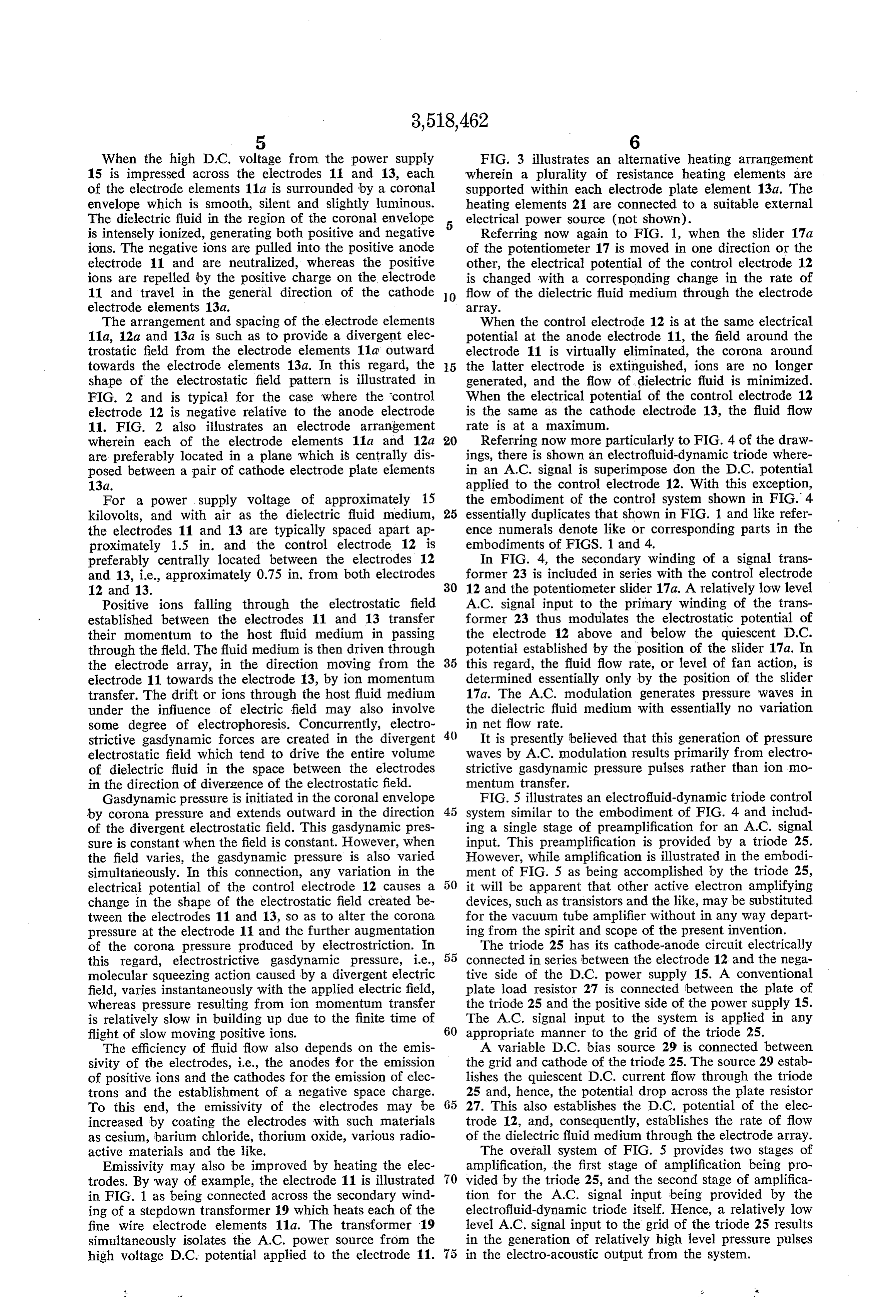
Gasdynamic pressure is initiated in the coronal envelope FIG. 5 illustrates an electrofluid-dynamic triode control by corona pressure and extends outward in the direction system similar to the embodiment of FIG. 4 and includ of the divergent electrostatic field. This gasdynamic pres ing a single stage of preamplification for an A.C. signal sure is constant when the field is constant. However, when input. This preamplification is provided by a triode 25. the field varies, the gasdynamic pressure is also varied However, while amplification is illustrated in the embodi simultaneously. In this connection, any variation in the ment of FIG. 5 as being accomplished by the triode 25, electrical potential of the control electrode 12 causes a 50 it will be apparent that other active electron amplifying change in the shape of the electrostatic field created be devices, such as transistors and the like, may be substituted tween the electrodes 11 and 13, so as to alter the corona for the vacuum tube amplifier without in any way depart pressure at the electrode 11 and the further augmentation ing from the spirit and scope of the present invention. of the corona pressure produced by electrostriction. In The triode 25 has its cathode-anode circuit electrically this regard, electrostrictive gasdynamic pressure, i.e., 55 connected in series between the electrode 12 and the nega molecular squeezing action caused by a divergent electric tive side of the D.C. power supply 15. A conventional field, varies instantaneously with the applied electric field, plate load resistor 27 is connected between the plate of whereas pressure resulting from ion momentum transfer the triode 25 and the positive side of the power supply 15. is relatively slow in building up due to the finite time of The A.C. signal input to the system is applied in any flight of slow moving positive ions. 60 appropriate manner to the grid of the triode 25. The efficiency of fluid flow also depends on the emis A variable D.C. bias source 29 is connected between sivity of the electrodes, i.e., the anodes for the emission the grid and cathode of the triode 25. The source 29 estab of positive ions and the cathodes for the emission of elec lishes the quiescent D.C. current flow through the triode trons and the establishment of a negative space charge. 25 and, hence, the potential drop across the plate resistor To this end, the emissivity of the electrodes may be 65 27. This also establishes the D.C. potential of the elec increased by coating the electrodes with such materials trode 12, and, consequently, establishes the rate of flow as cesium, barium chloride, thorium oxide, various radio of the dielectric fluid medium through the electrode array. active materials and the like. The overall system of FIG. 5 provides two stages of Emissivity may also be improved by heating the elec amplification, the first stage of amplification being pro trodes. By way of example, the electrode 11 is illustrated 70 vided by the triode 25, and the second stage of amplifica in FIG. 1 as being connected across the secondary wind tion for the A.C. signal input being provided by the ing of a stepdown transformer 19 which heats each of the electrofluid-dynamic triode itself. Hence, a relatively low fine wire electrode elements 11a. The transformer 19 level A.C. signal input to the grid of the triode 25 results simultaneously isolates the A.C. power source from the in the generation of relatively high level pressure pulses high voltage D.C. potential applied to the electrode 11. 75 in the electro-acoustic output from the system.
Page 6
A current limiting resistor 31 is included in series be 27a and 27b to the common high voltage positive side of tween the positive side of the power supply 15 and the the power supply 15.
anode electrode 11 to prevent any spark breakdown in The grids of both triodes 25a and 25b are connected the space between the electrodes 11 and 12 during exces to opposite ends of the center tapped secondary of a low. sive voltage peaks. level signal input transformer 35. Referring now to FIG. 6 of the drawings, there is shown An appropriate grid bias source 37 is connected be an electro-acoustic transducer, in accordance with the in tween the cathodes of the triodes 25a and 25b and the vention, which essentially utilizes a pair of electrofluid center tap of the secondary winding for transformer 25, dynamic triodes in a symmetrical push-pull arrangement providing D.C. bias for the triodes to their proper quies analogous to the conventional push-pull circuit configura 10 cent operating points. It will be apparent, of course, that tion for electronic amplifiers. other electronic preamplifying configurations, such as In the arrangement of FIG. 6, a single common anode those using solid state devices, may be substituted for the electrode 11 is utilized for the dual electrofluid-dynamic vacuum tube push-pull amplifier shown in FIG. 7 with triode arrangement. The anode electrode 11 is connected out departing from the scope of the invention. to the positive side of the high voltage power supply 15. 15 The electro-acoustic output provided by the electro A pair of control electrodes 12 are disposed on oppo fluid-dynamic triodes in the embodiments of FIGS. 4, 5, site sides of the electrode 11 and are electrically con 6 and 7 are characterized by extremely wide frequency nected to opposite ends of the secondary winding of an response, free from resonant peaks and mechanical dis input high voltage transformer 33. The secondary wind tortion. In this connection, the electrofluid-dynamic triode ing of the transformer 33 is center tapped and connected 20 portion of the transducer system, exclusive of electronic to the negative terminal of the power supply 15. signal input and pre-amplification devices which may The outer pair of cathode electrodes 13 of the push impose frequency limitations of their own, is capable of pull arrangement are also connected to the negative side essentially uniform frequency response from below 10 of the power supply 15. From a practical standpoint, it Hz. to well in excess of 100 kHz, since, as opposed to is also desirable to use the outer cathode electrodes 13 as 25 conventional loudspeaker arrangements, there is no protective grids at the sides of an appropriate enclosure speaker diaphragm mass to be moved. Only the molecules (not shown) and, hence, the electrodes 13 and the nega and ions of the dielectric fluid medium are oscillated. tive side of the power supply 15 are preferably grounded Moreover, the electro-acoustic transducers provided by to protect the ultimate user against high voltage shock. the present invention not only provide excellent trans Since the electrode arrangement of FIG. 6 is electri 30 ducer action, but simultaneously and inherently provide cally balanced, and the entire structure is in an enclosed a stage of signal amplification independent of any addi housing (not shown) which admits a dielectric fluid me tional preamplification that may be provided. Hence, in dium, such as air, only through the electrodes 13, there some instances, expensive power amplification may not is no net fluid flow through the system. In this regard, be needed, and the relatively low level A.C. signal input sound waves are generated by the electrical action upon 35 may prove sufficient to provide the desired level of elec the air column between the electrodes, first in one direc tro-acoustic output.
tion and then in the other, to provide push-pull opera The present invention satisfies a long existing need for tion which generates compressions and rarefactions alter new and improved electrokinetic apparatus capable of nately on each side of the electrode structure. more efficiently, economically and reliably controlling An A.C. signal input to the primary winding of the 40 fluid flow rate and pressure in an ionizable, dielectric transformer 33 is stepped up by the secondary winding fluid medium. Hence, the present invention provides an to produce relatively high opposing potentials (180° out improved, more versatile fluid pump, and a new and im of phase) between the pair of control electrodes 12 on proved electro-acoustic transducer which also provides opposite sides of the common anode electrode 11, so that inherent power amplification for a relatively low level pressure pulses are directed first one way, and then the signal input.
other way, to cause a push-pull generation of sound waves It will be apparent from the foregoing that, while par in the air column. ticular forms of the invention have been illustrated and Referring now to FIG. 7 of the drawings, there is described, various modifications can be made without de shown another embodiment of a push-pull electro-acous parting from the spirit and scope of the invention. Ac tic transducer in accordance with the invention. The em 50 cordingly, it is not intended that the invention be limited, bodiment of FIG. 7 differs from the embodiment of FIG. except as by the appended claims. 6 primarily in the use of vacuum tube preamplification, 1. A fluid flow control system, comprising: as opposed to the use of the high voltage transformer 33. a first electrode adapted to be immersed in an ionizable, In practice, the embodiment of FIG.7 may be preferred dielectric fluid medium;
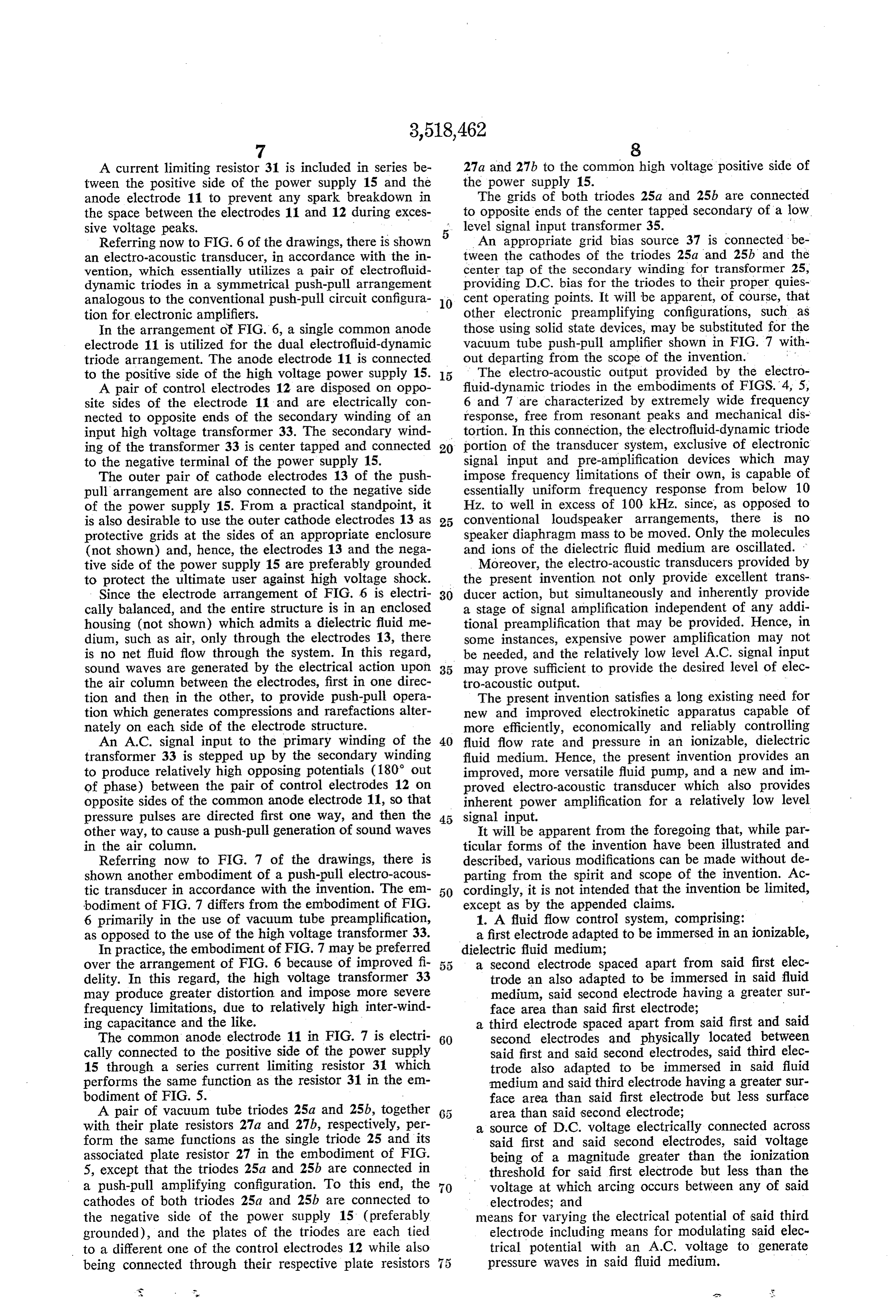
over the arrangement of FIG. 6 because of improved fi a second electrode spaced apart from said first elec delity. In this regard, the high voltage transformer 33 trode an also adapted to be immersed in said fluid may produce greater distortion and impose more severe medium, said second electrode having a greater Sur frequency limitations, due to relatively high inter-wind face area than said first electrode; ing capacitance and the like. a third electrode spaced apart from said first and said The common anode electrode 11 in FIG. 7 is electri 60 second electrodes and physically located between cally connected to the positive side of the power supply said first and said second electrodes, said third elec 15 through a series current limiting resistor 31 which trode also adapted to be immersed in said fluid performs the same function as the resistor 31 in the em medium and said third electrode having a greater Sur bodiment of FIG. 5. - face area than said first electrode but less surface A pair of vacuum tube triodes 25a and 25b, together area than said second electrode; with their plate resistors 27a and 27b, respectively, per a source of D.C. voltage electrically connected across form the same functions as the single triode 25 and its said first and said second electrodes, said voltage associated plate resistor 27 in the embodiment of FIG. being of a magnitude greater than the ionization 5, except that the triodes 25a and 25b are connected in threshold for said first electrode but less than the a push-pull amplifying configuration. To this end, the 70 voltage at which arcing occurs between any of said cathodes of both triodes 25a and 25b are connected to electrodes; and the negative side of the power supply 15 (preferably means for varying the electrical potential of said third grounded), and the plates of the triodes are each tied electrode including means for modulating said elec to a different one of the control electrodes 12 while also trical potential with an A.C. voltage to generate being connected through their respective plate resistors 5 pressure waves in said fluid medium.
Page 7
2. A fluid flow control system, comprising: trode and also adapted to be immersed in said fluid a first electrode adapted to be immersed in an ionizable, medium, said second electrode having a greater dielectric fluid medium; -4 surface area than said first electrode; a second electrode spaced apart from said first electrode a third electrode spaced apart from said first and said and also adapted to be immersed in said fluid medi second electrodes and physically located between um, said second electrode having a greater surface said first and said second electrodes, said third elec area than said first electrode; i trodes also adapted to be immersed in said fluid a third electrode spaced apart from said first and said medium, and said third electrode having a greater second electrodes and physically, located between surface area than said first electrode but less surface said first and said second electrodes, said third elec O area than said second electrode;
trodes also adapted to be immersed in said fluid a source of D.C. voltage electrically connected across medium, and said third electrode having a greater said second electrodes, said voltage being of a mag surface area than said first electrode but less surface nitude greater than the ionization threshold for said area than said second electrode; first electrode but less than the voltage at which arcing a source of D.C. voltage electrically connected across 5 occurs between any of said electrodes; and said first and said second electrodes, said voltage means for varying the electrical potential of said third being of a magnitude greater than the ionization electrode;
threshold for said first electrode but less than the said first and said third electrodes each comprising a voltage at which arcing occurs between any of said plurality of parallel wires and said second electrode comprises a plurality of parallel plates;
means for varying the electrical potential of said third each of said parallel wires of said first and said third electrode comprising first means for varying the D.C. electrodes lying in planes passing substantially mid electrical potential and second means for modulating way between adjacent pairs of said parallel plates the electrical potential with an A.C. voltage. of said second electrode.
3. A fluid flow control system, comprising: ". 25 6. A system for imparting movement to an ionizable, a first electrode adapted to be immersed in an ionizable, dielectric fluid medium comprising: dielectric fluid medium; a first electrode adapted to be immersed in said fluid a second electrode spaced apart from said first elec medium;
trode and also adapted to be immersed in said fluid 30 a second electrode spaced apart from said first elec medium, said second electrode having a greater trode and also adapted to be immersed in said fluid surface area than said first electrode; medium;
a third electrode spaced apart from said first and said a third electrode spaced apart from said first and said second electrodes and physically located between second electrodes and located between said first and said first and said second electrodes, said third elec 35 said second electrodes, said third electrode also trodes also adapted to be immersed in said fluid medi adapted to be immersed in said fluid medium; um, and said third electrode having a greater surface a source of D.C. voltage electrically connected to said area than said first electrode but less surface area electrodes such that the potential of said third elec than said second electrode; trode with respect to said first electrode is main a source of D.C. voltage electrically connected across tained negative and the potential of said second elec said first and said second electrodes, said voltage 40 trode with respect to said third electrode is main being of a magnitude greater than the ionization tained negative, the voltage on said electrodes being threshold for said first electrode but less than the of such relative magnitude as to cause ionization voltage at which arcing occurs between any of said adjacent said first electrode without arcing occur electrodes; and ring between any of said electrodes, the potential means for varying the electrical potential of said third 45 relationship between all said electrodes determining electrode; - the flow rate;
said third electrode being of electrically resistive ma said ionization generating positive and negative ions, terial to minimize inter-electrode arcing. the negative ions being attracted by said first elec 4. A fluid flow control system, comprising: trode and the positive ions being attracted away from a first electrode adapted to be immersed in an ionizable, 50 said first electrode toward said third electrode result dielectric fluid medium; - ing in movement of said medium. a second electrode spaced apart from said first elec 7. A system as defined in claim 6 having control means trode and also adapted to be immersed in said first for controlling the potential on said third electrode for medium, said second electrode having a greater sur producing a desired flow rate of said fluid medium. face area than said first electrode; 55 8. A system as defined in claim 6 wherein said second a third electrode spaced apart from said first and said and third electrodes have greater surface area than said second electrodes and physically located between first electrode.
said first and said second electrodes, said third elec 9. A system as defined in claim 6 having a current lim trode also adapted to be immersed in said fluid me iting resistor in series with one of said electrodes. dium, and said third electrode having a greater 60 10. A system as defined in claim 7 wherein said con surface area than said first electrode but less surface trol means comprises means for modulating said electrical area than said second electrode; potential on said third electrode. a Source of D.C. voltage electrically connected across 11. A system as defined in claim 6 wherein said second said first and said second electrodes, said voltage electrode has a greater surface area than said third elec being of a magnitude greater than the ionization 65 trode and said third electrode has a greater surface area threshold for said first electrode but less than the than said first electrode.
voltage at which arcing occurs between any of said 12. A push-pull, electro-acoustic transducer, compris electrodes; and Ing:
means for varying the electrical potential of said third a first electrode adapted to be immersed in an ioniz electrode including A.C. amplification means con 70 able, dielectric fluid medium; nected in series with said third electrode. a pair of second electrodes also adapted to be im 5. A fluid flow control system, comprising: mersed in said fluid medium and spaced apart from a first electrode adapted to be immersed in an ionizable, said first electrode on opposite sides thereof, each of dielectric fluid medium; said second electrodes having a substantially greater a second electrode spaced apart from said first elec 75 surface area than said first electrode;
Page 8
a pair of third electrodes also adapted to be immersed 13. A push-pull; electro-acoustic transducer as set forth imultaneously vary in said fluid medium, one each of said third elec trodes being located on opposite sides of said first of said third elec electrode between said first and one of said 'second ansconnected electrodes, each of said third electrodes having a s ignal input. greater surface area than said first electrode but less than the surface area of each of said second elec trodes;
a source of D.C. voltage electrically connected across 3,018,394.1/ said first electrode and both of said second elec id 3,374,941 "I 3/1968's Okress trodes, said voltage having a magnitude greater than the ionization threshold for 'said first electrode but 3,411,025; 11/1968, Marks.
less than the voltage at which arcing occurs between any of said electrodes; and . . . . . . DAVID X. SLINEY, Primary Examiner means for simultaneously varying the electrical poten 15 tials of both of said third electrodes.
Provenance
- Collection
- Cited prior art
- Original PDF
- patentimages.storage.googleapis.com →
- Filed
- 1967-08-21
- Pages
- 8
- Method
- pdftotext (the PDF's own text layer) + pdftoppm 300dpi page scans
- Source
- Google Patents bibliographic record
- Granted
- 1970-06-30
- Inventors
- Thomas Townsend Brown; Guidance Technology Inc
- Transcribed from
- patentimages.storage.googleapis.com →