patent · US3744882
Composite lens for an optical communication system providing directly viewed real images
10 July 1973
Page 1 — bibliographic record
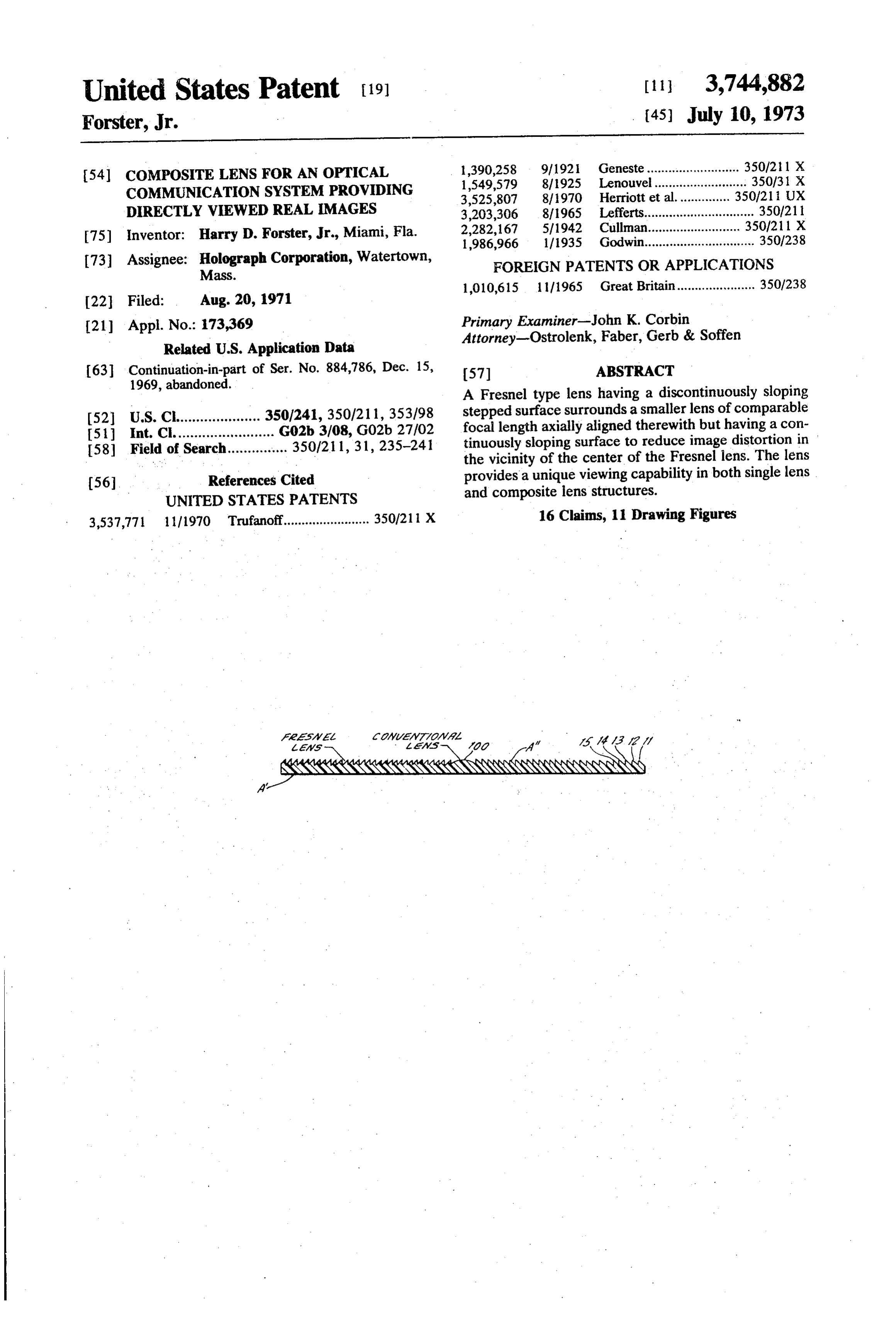
United States Patent (19) [11] 3,744,882 Forster, Jr. (45) July 10, 1973 54 COMPOSITE LENS FOR AN OPTICAL 1,390,258 9/1921 Geneste.......................... 350/21 1 X COMMUNICATION SYSTEM PROVIDING 1,549,579 8/1925 Lenouvel.......................... 350/31 X
DIRECTLY WEWED REAL IMAGES 3,203,306 8/1965 Lefferts............................... 350/211 75) Inventor: Harry D. Forster, Jr., Miami, Fla. 2,282,167 5/1942 Cullman.............. 350/21 1 X 1986,966 1/1935 Godwin............................... 350/238 73 Assignee: Holograph Corporation, Watertown, FOREIGN PATENTS OR APPLICATIONS Mass.
1,010,615 1 1/1965 Great Britain...................... 350/238
(21) Appl. No.: 173,369 Primary Examiner-John K. Corbin Attorney-Ostrolenk, Faber, Gerb & Soffen
Related U.S. Application Data 63 Continuation-in-part of Ser. No. 884,786, Dec. 15, 57 ABSTRACT 1969, abandoned. A Fresnel type lens having a discontinuously sloping (52) U.S. Cl..................... 350/241, 350/21 1, 353/98 stepped surface surrounds a smaller lens of comparable I51) Int. Cl......................... G02b 3/08, G02b 27/02 focal length axially aligned therewith but having a con 58) Field of Search............... 350/211, 31, 235-241 tinuously sloping surface to reduce image distortion in the vicinity of the center of the Fresnel lens. The lens 56 References Cited provides a unique viewing capability in both single lens UNITED STATES PATENTS and composite lens structures.
3,537,771 1 1/1970 Trufanoff........................ 350/21 X 16 Claims, 11 Drawing Figures
Page 2
Drawing sheet — no readable text.
Page 3
Drawing sheet — no readable text.
Page 4
Drawing sheet — no readable text.
Page 5
Drawing sheet — no readable text.
Page 6
COMPOSTE LENS FOR AN OPTICAL did not appear to introduce too objectionable a distor COMMUNICATION SYSTEM PROVIDING tion when a lens size acceptable for highway signing DIRECTLY WIEWED REAL MAGES was needed (e.g., 200-500 square feet), but did prove This application is a continuation-in-part application objectionable in advertising displays (of some 5-10 of Ser. No. 884,786 filed Dec. 15, 1969 now aban square feet area, for example) where the distortion oc doned. cupied a not insignificant portion of the overall surface This invention relates to a composite lens arrange display (approximately 4 square inches). ment for use in an optical communication system pro OBJECTS OF THE INVENTION viding directly viewed real images. Such a system is de scribed in my pending application, Ser. No. 850,021, 10 provide it is an object of the present invention, therefore, to filed Aug. 14, 1969 and abandoned in favor of con viewed real an improved lens construction for a directly tinuation-in-part application Ser. No. 173,368 filed imaging system where image distortion is Aug. 20, 1971, entitled "Optical Communications Sys kept low.
tem. Providing Selective Image Presentations,' and as 5 It is another object of the invention to provide such signed to the same assignee as this instant application. an improved construction which maintains reasonable image sizes and viewing angles and holds down the
BACKGROUND OF THE INVENTION bulkiness of the lens employed.
One feature of the optical communication system of structionAs will become clear hereinafter, the improved con my aforesaid application is that the spectrum over 20 of the present invention comprises a compos ite lens having which an image can be seen is controllable. That is, by The outer section first and second concentric sections. adjusting the viewing cone, information can be selec discontinuously sloping includes a Fresnel-type lens with a tively presented to only a desired set of viewers, exclud stepped surface configuration ing all others. Information can, in this manner, be pro while the inner section includes a lens of continuously jected only to right lane drivers on a super highway. 25 sloping configuration. Both configurations are of com Further, by projecting different messages in each of parable focal length and thickness, with the Fresnel ar several viewing cones, multiple messages can be pro rangement surrounding the continuously sloping ar jected from a single source. As is there described, such rangement. In one particularly attractive embodiment an optical communication system also proves attractive of a the invention, the continuously sloping lens was of spherical plano-convex construction.
as a new dimension in advertising displays.
Some of the advantages of that optical communica 30 clearly These and other objects of the invention will be more tion system are as follows: understood from the following description a. the system has the ability to selectively present in taken in connection with the accompanying drawings, formation to viewers according to their needs and posi in which:
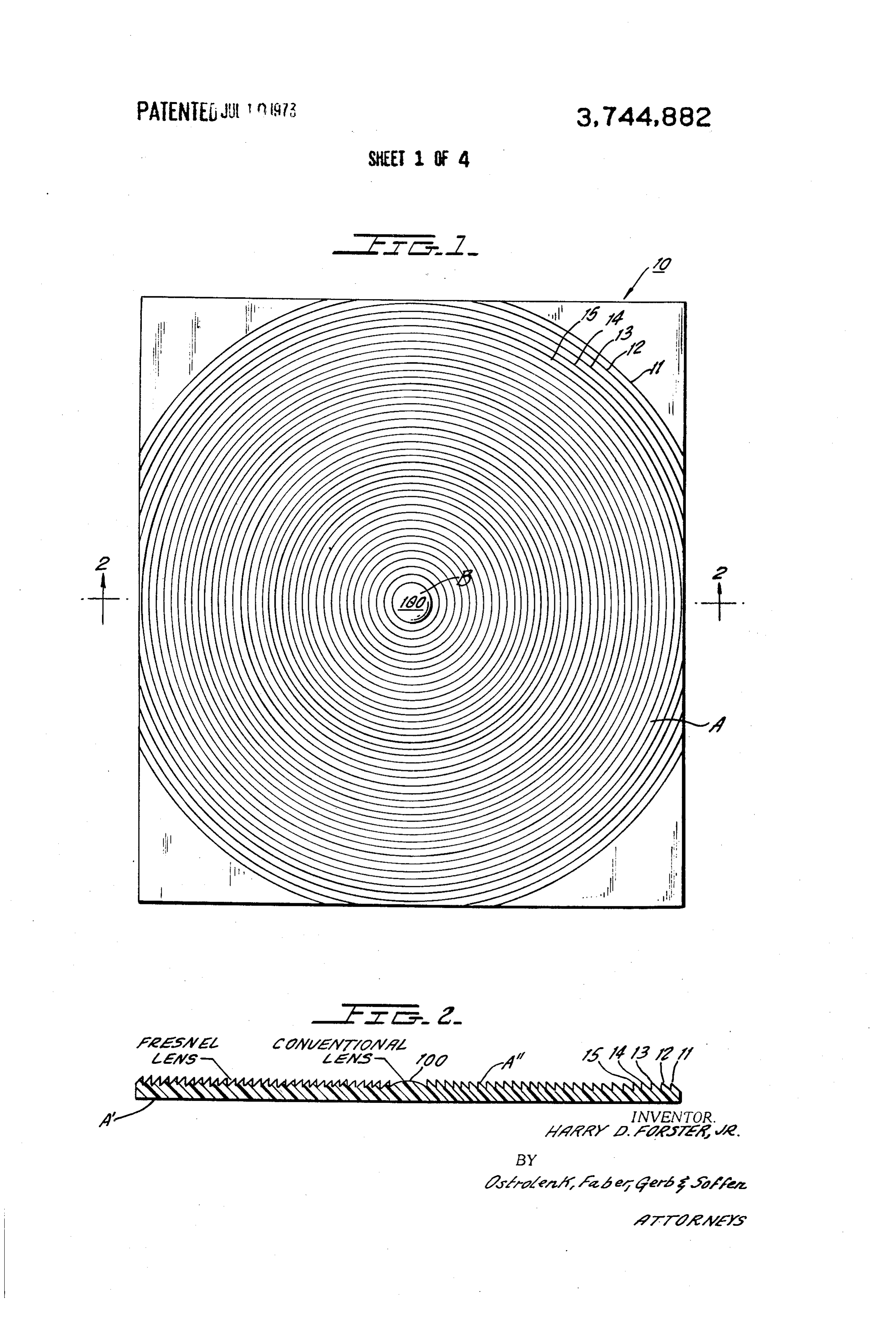
tion, enabling presentation of unique information to 35 BRIEF DESCRIPTION OF THE FIGURES different traffic lanes or to separate audience locations; FIG. 1 shows a top view of an improved lens con b. the information can effectively be suspended in space as an aerial image without the need for a physical structed in accordance with one embodiment of the obstruction, such as a screen; present invention;
c. the system permits control of projection distances 40 FIG. 2 shows a cross-sectional view of the lens of and viewing angles so that images appear to move with FIG. 1;
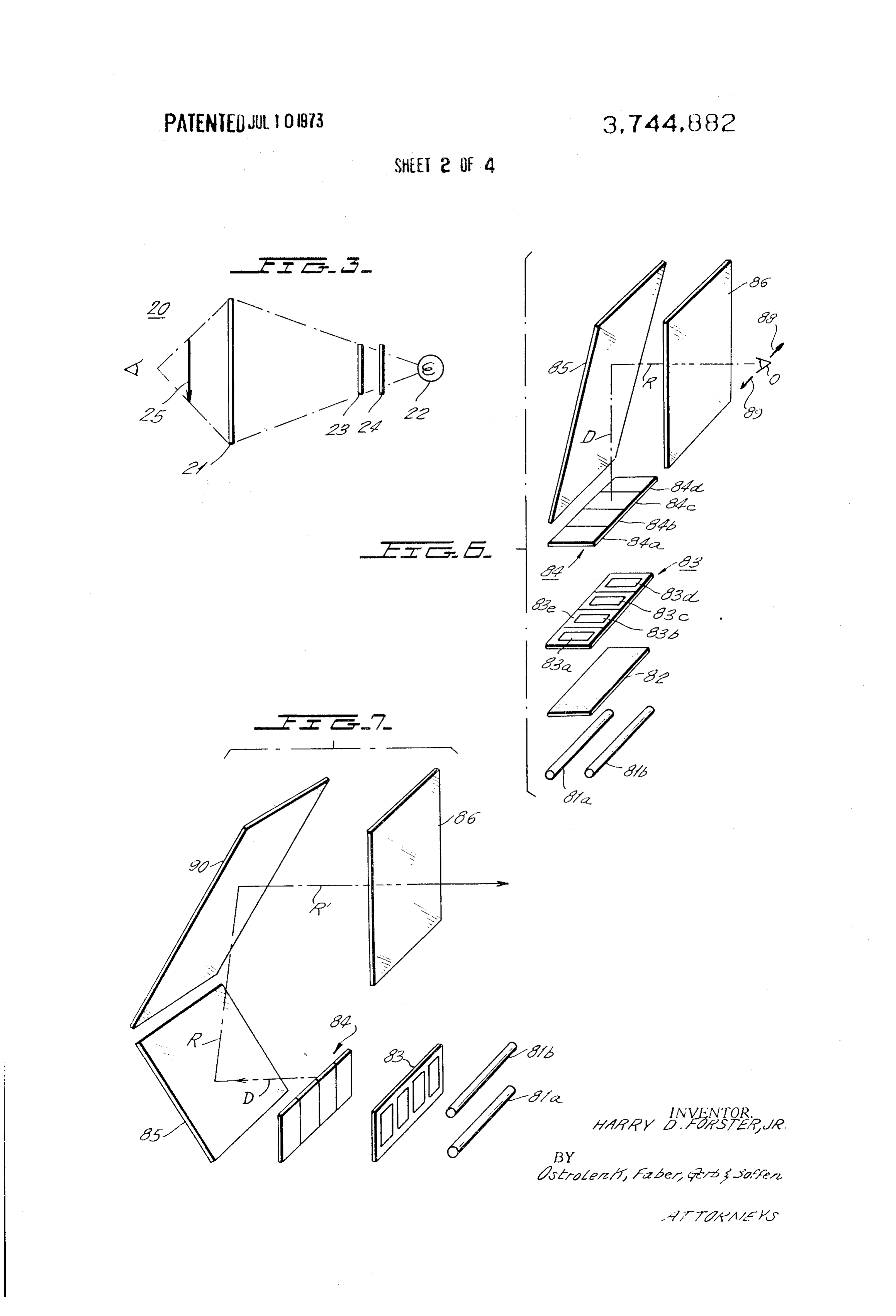
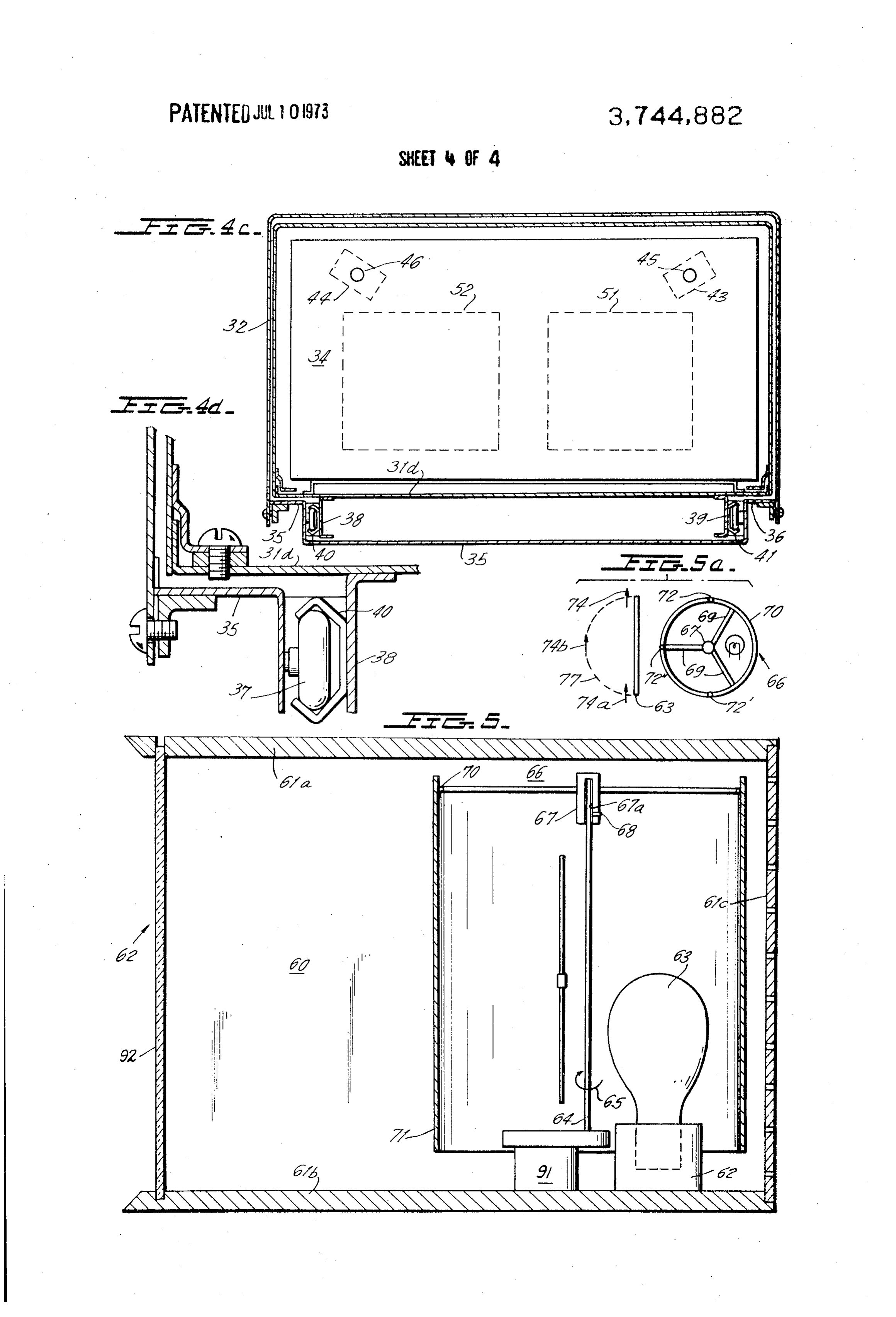
the observer, to increase visual effectiveness; and FIG.3 is a schematic diagram showing one preferred d, the system lends itself to reduced vandalism be apparatus employing the Fresnellens of the type shown cause images are not formed on a physical mass which in FIGS. FIGS. 1 and 2;
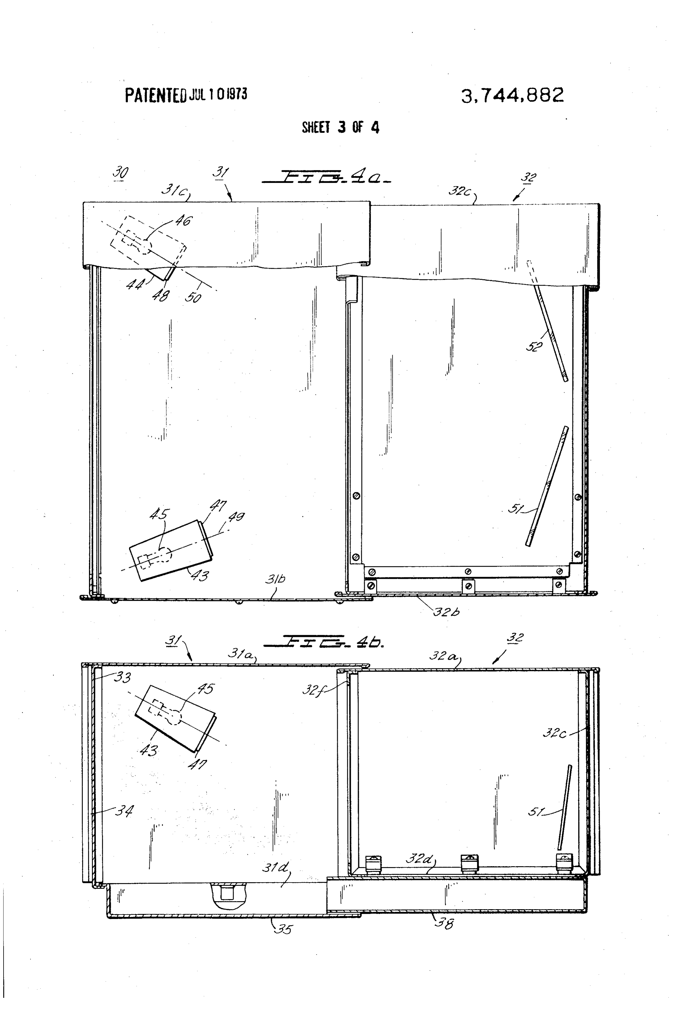
4a–4a are elevational, top and front views of can be damaged or destroyed.
One arrangement for the optical source of my Ser. 45 another preferred embodiment of the present invention No. 850,021 system includes a Fresnel lens. Such with portions of the housing of the embodiment being lenses typically comprise built-up annular rings ground removed in FIGS. 4a and 4b to reveal the contents in steps or concentric circular areas. The centers of thereof;
FIG. 4d is an enlarged view showing a portion of the curvature of the different rings progressively recede 50 slidable coupling arrangement of FIG. 4c; from the central axis to reduce spherical aberration. In FIG. 5 shows a sectionalized elevational view of still the design of such lenses, the variables of interest in another preferred embodiment of the present inven clude the radius to the center of each step, the index of refraction with respect to air of the material used for tion;
the lens, the focal distance from the back of the lens to 55 FIG. 5a shows a simplified top plan view of the em the plane of the image for an object at infinity, the bodiment of FIG. S; and thickness of the lens and the width of each step. The FIGS. 6 and 7 are perspective views showing still advantage of using such lenses is that large aperture other preferred embodiments of the present invention. systems may be constructed at low cost. Construction of these Fresnel-type lenses can be had in a modestly
DETAILED DESCRIPTION OF THE FIGURES
equipped machine shop from a variety of materials, in The improved lens of the drawings is especially useful cluding plastics. in optical communication systems providing directly In developing the directly viewed real images of the viewed real inimages. The lens 10 is illustrated as being optical communication system of my Ser. No. 850,021 rectangular nature, although this particular configu application, it was found that a distortion was intro 65 ration is not critical. One embodiment of the system of my Ser. No. 850,021 application employed such a rect duced in the area of the center of the Fresnel lens. The angular lens since the housing for the system was of distortion, furthermore, appeared to be fairly indepen corresponding dent of lens size; thus, use of the Fresnel lens structure shape. The coaxial lens 10 was there ap
Page 7
proximately three feet in length and two and one-half tially equal indices of refraction in all parts employed. feet in width to provide a total viewing area of some In the embodiment of the invention empioying the seven and one-half square feet. rectangular Fresnel sheet of some seven and one-half The improved lens iO of FIGS. 1 and 2 includes a square foot area, it was found that the insertion of a Fresnel lens section A. The discontinuously sloping spherical plano-convex lens of three or four square stepped rings of such a section are illustrated by the ref inch area or so substantially reduced the distortion to erence numerals ill, E2, i3, etc., and may be machiaed the directly viewed real image. Substitution of such a to an appropriate width extending down to a few thou lens for the central portion of a much larger Fresnel sandths of an inch wide. This machining may be done construction would similarly reduce distortion of an in a modestly equipped machine shop from a plastic O image at the optical axis as well, though the observance material such as Lucite, applying a commercial pene of this reduced distortion would be less pronounced. trating oil as the cutting fluid ahead of the cutting tool. Thus, in the described environments, lens systems may As employed in the optical communication system of be employed using Fresnel configurations to keep bulk my aforesaid application, the smooth side A" of the and cost down while using piano-convex or piano Fresnel section is oriented toward the information 5 concave configurations in composite arrangements to source while the stepped face A' is oriented toward minimize image distortion.
the viewer. As will be appreciated, different features attach to I have observed that the image viewed through this the selection of the particular type of continuously Fresnel lens, by one moving generally paralliei to it is sloping lens section B; a spherical lens construction is noticeably distorted particularly in the vicinity of the 20 easier to manufacture while an aspheric construction center of the lens, i.e., at the optical axis of the compos provides better imaging qualities for defined conjugate ite lens construction. I have further observed that this points. Similarly, the piano-concave lens affords a neg distortion covered an area of some 4 square inches and ative focal length construction permitting an increase caused "smearing' of the resultant image at that axis. 25 in the field of depth without the need for additional While distortion of this nature might be tolerable in space requirements, so as to be useful in tunnei settings large aperture constructions where the distortion cov and wall mounting environments. The plano-convex ers only a smail portion of the overall display, the dis lens, on the other hand, proves quite useful in the high tortion in aperture arrangements of the order of tens of way signing and advertising display applications where square feet, and less, would be quite disconcerting. 30 the positive focal length exhibited is made use of in pro Such large constructions are typical in directly viewed jecting an image towards a viewer. Regardless of the highway signing systems where areas 500 square feet type of continuously sloping lens selected, however, the and more are normally encountered to make informa reduction in image distortion should be readily observ tion presentations visible at distances of hundreds of able.
feet. Such smaller constructions may be found in de 35 FEG. 3 shows one preferred embodiment 20 of the partment store advertising counter displays, for in present invention winich comprises a Fresnel lens 2 stance, where visibility of much less distance ranges are having substantially the structure as shown in FiGS. i desired. While images, in general, can be predistorted and 2. A light source 22 is positioned to the right of to compensate such introduced distortion, such predis Fresnel lens 22. A transparency 23 is positioned be tortion is not very effective in display environments tween the Fresnel lens and the light source and a dif where the information presented to the observer de 40 fuser panel 24 is positioned between the transparency pends on his location and position relative to the dis 23 and the light source. The diffuser panel 24 is prefer play and where the degree of distortion introduced de ably a translucent member such as, for exampie a pends on his viewing angle. In such environments, the smoked glass or white plastic panel. In the embodiment distortion observed along the optical axis of a Fresnel 45 20 of FEG. 3 the viewer is positioned to the left of Fres iens could limit the usefulness of the directly viewed nel lens 2i. The image viewed by the observer is desig real image system and be a factor mitigating against its nated by the arrow 25 and can be seen to be positioned St. in front of (i.e., to the left of) the aperture lens 21. Ap However - and in accordance with the present in propriate positioning of the Fresnel aperture lens 2 vention - the improved lens 16 of the drawings in relative to the transparency or other image 23 may be ciudes a lens section B having a continuously sloping 50 made adjustable so as to create the image viewed by the surface in the vicinity of the optical axis of the Fresnel observer to appear behind (i.e., to the right of) aper section A, instead of having the discontinuously sloping ture lens 21. The use of a Fresnel lens in this manner Fresnel construction uniform throughout the lens. Such is enhanced when the object distance (i.e., the distance a lens section B may be of a plano-convex or piano 55 from the lens 25 to the object of transparency 23) is in concave configuration, and may be spherical or creased so as to be in a range from 1-% - 3 times that aspheric in nature. This second lens section B is se of the object distance used for Fresnel lenses when op lected of a focal length and thickness comparable to erating in its intended manner. Alternatively, the Fres that of the Fresnel configuration, and might be formed nel iens may be so designed as to utilize the conven through a separate machine step during the fabrication 60 tional object distance for conventional Fresnel lenses of the resulting composite lens. Alternatively, the lens but to change the contour of the Fresnel lens employed of the invention might be formed as an entire Fresnel so as to obtain the same optical effect as if the object arrangement, with its central portion being later re distance between a conventional Fresnei lens and the moved and a spherical plano-convex lens 100, for ex object is 1-% - 3 times that normally employed in con ample, of comparable focal length and thickness being 65 ventional Fresnel lenses.
fitted in its place. it will be appreciated that the secur FIGS. 4a-4c show a top view, end view and front ing of the central lens to the Fresnel construction in this view, respectively, of another preferred embodiment of latter arrangement would be such as to insure substan - the present invention employing the basic concept of
Page 8
the embodiment of FIG. 3 wherein portions of the the same manner as is described in copending applica housing are shown as being removed so as to reveal the tion Ser. No. 850,021 referred to hereinabove. Thus, internal structure thereof. The embodiment 30 is com the location of the observer relative to the viewing ap prised of first and second housing portions 31 and 32 paratus is determinative of that image which will be which telescope into one another. Housing portion 31 viewed. In the embodiment shown in FGS. 4a–4a, the is comprised of a top wall 31a, two side walls 31b and viewing cones developed by the separate transparen 31c. The left-hand end of housing portion 30 is fitted cies are non-overlapping so that the observer when with a rectangular shaped mask 33 which serves as the moving from one moving cone into the other experi frame for a Fresnel lens 34. The right-hand end of ences no overlapping of images but alternatively sees a housing portion 31 (relative to FIGS. 4a and 4b) is O rather abrupt change in the image viewed. open and is adapted to telescopingly receive the left F.G. 5 shows still another preferred embodiment 60 hand end of housing portion 32 which is comprised of of the present invention which is comprised of a hous a top wall 32a, first and second side walls 32b and 32c, ing havinga top and bottom walls 6a and 61b, a right and a bottom wall 32d. A rear wall 32e seals off the rear hand or rear wall 6c and a front opening 62 into which end of housing portion 32 while a rectangular shaped 15 a Fresnel lens 63 is fitted. The left and right-hand side frame portion 32f is employed to increase the struc walls have been omitted from FIG. 5 for purposes of tural strength of housing portion 32. Housing portion simplicity.
31 is provided with brackets 35 and 36 secured along The bottom wall 61b of the housing supports a socket its bottom wall 31d. Each of the brackets is provided 62 for receiving light source 63 which may, for exam with free-wheeling rollers (only one of which is shown 20 ple, be an incandescent bulb. Alternatively, a fluores in FIG. 4d) arranged at spaced intervals along each of cent tube or any other suitable light source may be pro the brackets 35 and 36. The underside of housing por vided. A motor 91 is mounted upon bottom wall 6d tion 32 is fitted with a pair of brackets 38 and 39. A and is provided with an elongated output shaft 64 channel shaped member 40 and 41 (note especially which rotate in the manner indicated by arrow 65. A FIG. 4c) is secured to each of the brackets 38 and 39, 25 structure 66 which substantially resembles that of a respectively, so as to embrace the free-wheeling rollers conventional lampshade is mounted to rotate upon in the manner shown. The cooperating free-wheeling shaft 64. The top view of this structure 66 is shown best rollers 37 and channel shaped members 40 and 41 in FIG. 5a and comprises a collar member 67 having an function to permit the housing portion 32 to be inserted 30 elongated opening 67a for receiving the top end of more deeply into housing portion 31 or, alternatively, shaft 64. A set screw 68 may be provided to secure to be withdrawn from housing portion 31 so as to con shaft 64 within opening 67a. Collar 67 is provided with trol the distance between the transparency or image a plurality of outwardly directed radially aligned sup and the Fresnel lens, in a manner to be more fully de porting spokes 69 which are secured at their outer free scribed. ends to a circular shaped frame 70. A hollow cylindri Housing portion 31 is provided with a pair of enclo 35 cal shell 7 is secured to ring 70 and is provided with sure assemblies 43 and 44, each of which are secured images, transparencies or other data or information to housing portion 31 in any suitable fashion. The hous around its circumference. For purposes of understand ings are employed to support light sources 45 and 46, ing the uniqe effect obtained through this apparatus, let respectively, as can best be seen in FIGS. 4a and 4b. it be assumed that an arrow is formed upon the cylin The right-hand end of each of the housings 43 and 44 40 drical shell 71 at the point 72. With motor 91 energized is fitted with a transparency 47 and 48 through which the arrow will move from the point 72 as shown in FIG. the light rays pass. As can best be seen from a consider 5a to point 72" which constitutes movement through ation of FIGS. 4a and 4b, the longitudinal axes of the one-half of a full revolution. In conventional structures, housings represented by the dotted lines 49 and 50 are 45 this would cause the image to move across the screen diagonally aligned relative to a horizontal plane (i.e., from the position occupied by image 74 to the position the plane of FIG. 4a), as well as being diagonally occupied by image 74a. This would be viewed, for ex aligned relative to a vertical plane (the plane of FIG. ample, through a back-lighted screen where the move 4b). ment of the cylindrical shell member 71 would clearly Housing portion 32 is fitted with a pair of reflective 50 be viewable through such a back-lighted screen which surfaces which may, for example, be the mirrors 51 and may, for example, be located at the position of Fresnel 52 which are likewise aligned diagonally relative to a lens 92 (note FIG. 5a). The unique effect of the present horizontal plane (the plane of FIG. 4a) as well as being invention causes the image, in addition to moving diagonally aligned relative to the vertical plane (the across the screen, to move to the front of the screen plane of FIG. 4b). The rays emanating from transpar 55 along a dotted line path designated by numeral 77. ency 48 strike mirror 51, while the rays emanating from Thus, when the arrow provided on cylindrical shell transparency 49 strike mirror 52. The reflected rays are moves from the position 72" to the position 72', its directed toward the left (relative to FIGS. 4a and 4b) image 74b will appear in the middle of the viewing ap so as to pass through Fresnel lens 34. By adjustment of erture and will further appear to be positioned much the rear housing portion 32 relative to the front housing 60 further to the left of aperture lens 92 than, for example, portion 31, the distance between the transparencies the images 74 and 74a, thereby creating an unusual and the Fresnel lens 34 may be adjustably controlled. and rather psychedelic effect not heretofore possible In the embodiment of FIGS. 4a-4d, the adjustable fea through conventional imaging systems. ture permits the images formed to be positioned in FIG. 6 is a perspective view showing still another pre space within a range aligned at a point 8 feet to the left 65 ferred embodiment of the present invention in which of Fresnel lens 34 to a second point which is located 2 the apparatus 80 shown therein comprises a light feet to the left of Fresnel lens 34. The positioning of the source including a pair of fluorescent tubes 81a and observer determines that image which will be viewed in 81b. Positioned above the light sources are a diffuser
Page 9
panel 82 (which may, for example, be a translucent lens having a predetermined focal length and thick sheet); a transparency assembly 83, a four-element lens neSS, 84; a diagonally aligned mirror 85; and an aperture lens said first lens section including a lens of focal length and thickness comparable to that of said Fresnel
The transparency cartridge in the embodinent type lens but of continuously sloping smooth sur shown is comprised of four individual transparencies face to reduce image distortion in the vicinity of 33a-33d arranged with a suitable frame 33e. The four the optical axis of said Fresnel type lens, the re element lens assembly is comprised of four individual maining surfaces of said first and second lens sec ienses 84a–84d arranged in spaced parallel fashion to 10 tions being fiat and coplanar; the diameter of said the transparency cartridge 83 and aligned whereby first lens section being substantially greater than each of the lens elements is associated with one of the twice the distance between adjacent grooves of transparencies. Reflective surface of mitor 35 is posi said second lens section;
tioned so as to deflect direct rays D so that the reflected said composite lens being positioned between the ob rays R pass through the aperture lens 86. The lenses 5 ject to be viewed and an observer to create an 84a-84d and the aperture lens 86 may, forexample, for image in space which image is located between the example, be Fresnel lenses of the type described here viewer and the lens and viewable without the need inabove. Depending upon the position of an observer for display of the image upon a viewing surface. O, only one of the four images will be visible and, 2. The composite lens of claim i in which said Fres movement of the observer in either of the two direc 20 nel type lens comprises a built-up annular arrangement tions shown by arrows 88 and 39 cause the images to of stepped rings of concentric circular areas which are be abruptly changed. One unique feature of the ar oriented toward the observer for viewing an image in rangement shown in FiC. 6 is such that the image space.
viewed will fill the entire aperture of lens 36. Depend 3. The composite tens of claim in which said dis ing upon the relative positioning distance of the trans 25 continuously sloping Fresnel type lens is of substan parencies to the first four-element lens structure and tially greater surface area than said continuously slop the distance between the four-element lens structure ing lens with which it is coaxial and which it surrounds. 84 and the aperture lens 86 (measured along the lines 4. The composite lens of claim 3 in which said dis D and R) will control the relative positioning of the continuously sloping Fresnel type lens and said contin image viewed by the observer so that the image can be 30 uously sloping lens are formed from a single body of thereby adjusted to appear either in front (i.e., to the transparent material.
right) of aperture lens 86 or behind (i.e., to the left of) 5. The composite lens of claim 3, in which said dis aperture lens 86 to create either of the two desirable continuously sloping Fresnel type lens includes a cut effects. out portion in the vicinity of its optical axis and in FIG. 7 shows a slightly modified arrangement from 35 which said continuously sloping lens is matingly se that of FIG. 6 which is referred to as a "double-folded.' cured as an insert to said Fresnel type lens at said cut arrangement wherein a pair of diagonally aligned mir out portion.
rors are employed. Like elements as between FGS. 6 6. The composite lens of claim3 in which said contin and 7 have been designated by like numerals, the major uously sloping lens is of plano-convex construction. distinction being the double-folded effect created as a 40 7. The composite lens of claim3 in which said contin result of the use of the additional mirror 90 whereby uously sloping lens is of plano-concave construction. light rays passing through four-element lens structure 8. The composite lens of claim3 in which said contin 84 (direct ray D) are reflected upwardly (reflected ray uously sloping lens is of spherical construction. R) and are then reflected horizontally and to the right 9. The composite lens of claim 3 in which said contin (second reflected ray R") so as to pass through aperture 45 uously sloping lens is of aspheric construction. lens 86. The advantage of the arrangement of FiG. 7 is 10. An optical system for creating visually observable that the distance between four-element lens structure images suspended in space comprising 84 and aperture lens 86 (measured along the lines D, a Fresnel lens of the type described in claim ; R and R') can be substantially greater, while at the 50 an object to be projected positioned a spaced dis same time the structure can be packaged within a more tance from said lens whereby the image of the ob confined space than the structure of FIG. 6, for exam ject created by said lens is viewable at a location on ple. The optical effects, however, remain substantially the opposite side of said lens; the same as those described in connection with F.G. 6. the distance of said object from said lens being such The embodiments of the invention in which an exclu as to create an image positioned a second spaced sive privilege or property is claimed are defined as fol 55 distance from said lens and at a position between lows: said lens and an observer. 1. For use in an optical communication system pro ii. The system of claim 10 wherein said object is a viding directly viewed images of an object, a composite photographic transparency;
a light source positioned to emit light rays which pass a first lens section; and through said transparency and impinge upon said a second lens section concentric with said first sec lens whereby said lens refracts the light rays pass tion and completely surrounding said first section; ing through said lens to create an image of the ob said second lens section including a Fresnel type lens ject.
having a discontinuously sloping surface forming a 65 12. The system of claim 11 further comprising a plurality of circular grooves of increasing diameter translucent panel positioned between said light source for projecting an illuminated image for viewing in and said transparency for diffusing the light rays pass space without the use of a screen, said Fresnei type ing therethrough toward said transparency.
Page 10
13. An optical system for creating visually observable a light source positioned within said shell for emitting images suspended in space comprising light rays passing through said shell; a Fresnel lens of the type described in claim i; means for rotating said shell about its longitudinal an object to be projected positioned a spaced dis- . aXáS, tance from said lens whereby the image of the ob 5 a lens of the type set forth in claim 1 being positioned ject created by said lens is viewable at a location on exterior of said shell and adapted to create an the opposite side of said lens; image of said information which image is sus the distance of said object from said lens being such pended in space and positioned a spaced distance as to create an image positioned a second spaced from the plane of said lens, said image transversing the aperture of said lens as said shell is rotated;
distance from said lens and at a position between - O whereby said lens and said object. the distance of said image from the piane 14. An optical system for creating a plurality of in of said lens changes as the distance of the informa ages selectively viewable at predetermined locations tion on said shell from the plane of said lens relative to said system comprising changes.
a plurality of lenses arranged in coplanar side by side 5 in 16.
space
An optical system for creating images suspended and selectively viewable at differing positions fashion, each of said lenses being of the type set comprising:
forth in claim 1; a first housing portion comprising a first hollow en a plurality of photographic transparencies arranged in coplanar side-by-side fashion and being arranged closure, in spaced parallel fashion relative to said plurality a second housing portion comprising a second hollow of lenses whereby each lens is associated with a enclosure telescopingly received by one end of said predetermined one of said transparencies; first enclosure;
a light source arranged to direct light rays toward a lens of the type set forth in claim 1 being positioned said transparencies; in the opposite end of said first enclosure; an aperture lens of the type described in claim 25 a pair of light sources positioned near the said oppo being positioned a spaced distance from said plu site end of said first enclosure; rality of lenses and cooperating with said plurality a transparency positioned between an associated one of lenses to create an image of each transparency, of said light sources and the first end of said first which images are suspended in space and substan enclosure;
tially fill the aperture, each of said images being 30 means surrounding each light source and its associ ated transparency for guiding light rays toward op viewable by an observer from the side of said aper ture lens opposite said transparencies whereby said posite diagonal corners of said second enclosure; images are viewable at different angular positions first and second reflective members being positioned relative to the optical axis of said aperture lens. adjacent the aforesaid diagonal corners of said sec 15. An optical system for creating a rotatably mov 35 ond enclosure for reflecting light rays directed ing image comprising from their associated transparencies toward said a cylindrical shell having information to be displayed lens whereby said lens creates images in space arranged around its periphery; viewable without need for a viewing surface and means for rotatably mounting said shell about its located at different
regionsk in. space.
Provenance
- Collection
- Cited prior art
- Original PDF
- patentimages.storage.googleapis.com →
- Filed
- 1971-08-20
- Pages
- 10
- Method
- pdftotext (the PDF's own text layer) + pdftoppm 300dpi page scans
- Source
- Google Patents bibliographic record
- Granted
- 1973-07-10
- Inventors
- H Forster; HOLOGRAPH CORP
- Transcribed from
- patentimages.storage.googleapis.com →