patent · US4405594
Photo separatory nozzle
20 September 1983
Page 1 — bibliographic record
United States Patent (19) (11) 4,405,594 Pyle 45) Sep. 20, 1983 (54) PHOTO SEPARATORY NOZZLE 4,053,576 10/1977 Fletcher .......................... 423/648 R
(75) Inventor: Walter R. Pyle, Richmond, Calif. 4,235,606 1 1/1980 Becker et al. ........................... 55/17 4,246,007 1/1981 Becker et al. ........................... 55/17 (73) Assignee: Chevron Research Center, San
Francisco, Calif. FOREIGN PATENT DOCUMENTS 21 Appl. No.: 304,131 916065 12/1972 Canada .................................... 55/17 54-123695 9/1979 Japan ...................................... 55/17 22) Filed: Sep. 21, 1981 1439284 6/1976 United Kingdom .................... 55/17
(51) Int. Cl. .............................................. C01B 13/00 (52) U.S. Cl. ........................................ 423/579; 55/15; Primary Examiner-O. R. Vertiz 55/17; 55/392; 422/128; 422/186; 423/648 R; Assistant Examiner-Wayne A. Langel 423/659 Attorney, Agent, or Firm-D. A. Newell; E. J. Keeling;
(58) Field of Search ................... 423/579, 648 R, 659; R. H. Evans 22/128, 129, 186, 198, 240; 55/15, 17, 392; 57 ABSTRACT
References Cited A system for the thermal dissociation of gaseous matter (56) into its component parts using solar energy and a molec
3,362,131 l/1968 Becker .................................... 55/17 3,877,892 4/1975 Bley et al. ............................... 55/17 6 Claims, 3 Drawing Figures
Page 2
Drawing sheet — no readable text.
Page 3
Drawing sheet — no readable text.
Page 4
Drawing sheet — no readable text.
Page 5
one or more molecular species. Generally, the species is
PHOTO SEPARATORY NOZZLE heated by concentrated solar energy to thermally disso ciate the species into its component parts. The compo
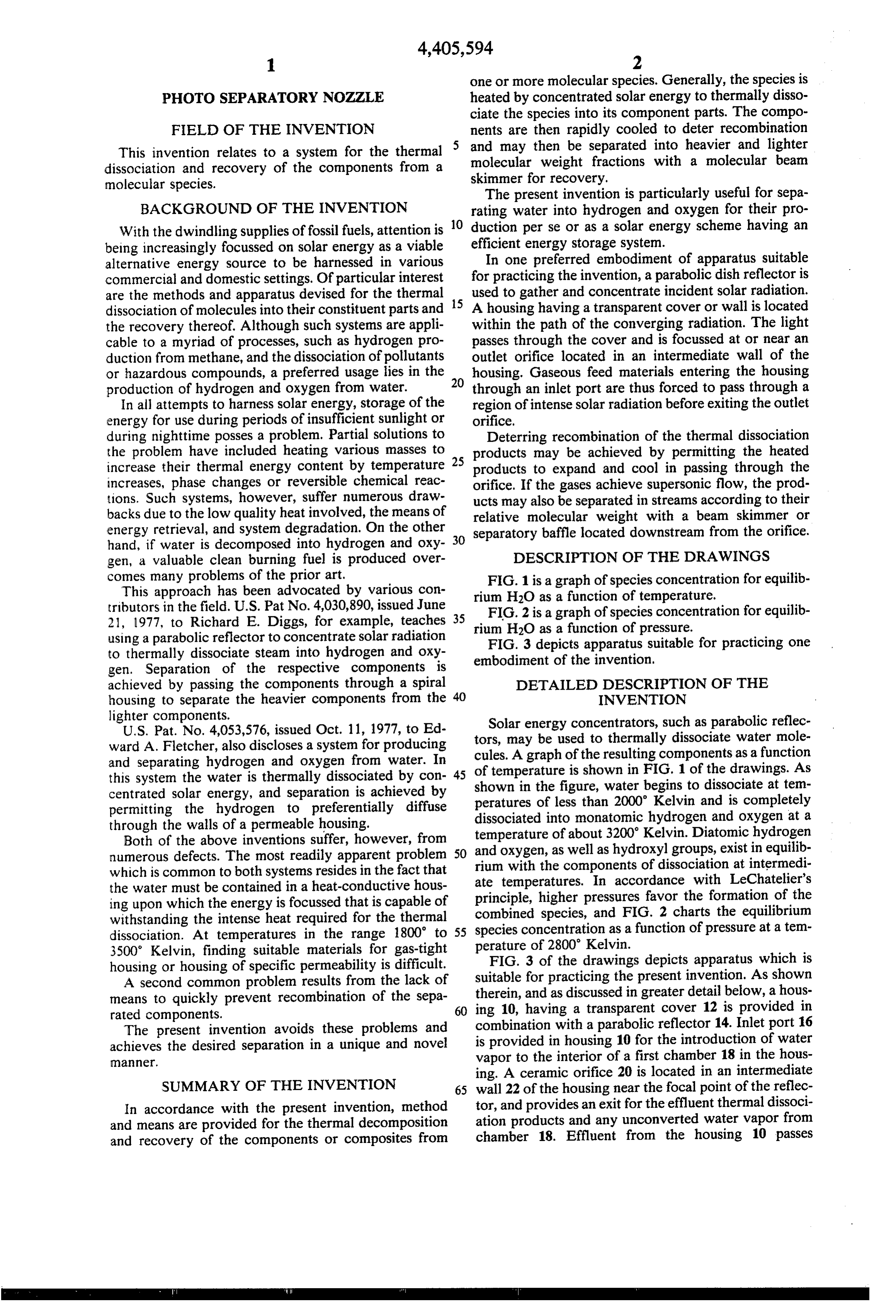
FIELD OF THE INVENTION nents are then rapidly cooled to deter recombination This invention relates to a system for the thermal and may then be separated into heavier and lighter dissociation and recovery of the components from a molecular weight fractions with a molecular beam molecular species. skimmer for recovery.
The present invention is particularly useful for sepa
BACKGROUND OF THE INVENTION rating water into hydrogen and oxygen for their pro With the dwindling supplies of fossil fuels, attention is 10 duction per se or as a solar energy scheme having an being increasingly focussed on solar energy as a viable efficient energy storage system.
alternative energy source to be harnessed in various In one preferred embodiment of apparatus suitable commercial and domestic settings. Of particular interest for practicing the invention, a parabolic dish reflector is are the methods and apparatus devised for the thermal 15 used to gather and concentrate incident solar radiation. dissociation of molecules into their constituent parts and A housing having a transparent cover or wall is located the recovery thereof. Although such systems are appli within the path of the converging radiation. The light cable to a myriad of processes, such as hydrogen pro passes through the cover and is focussed at or near an duction from methane, and the dissociation of pollutants outlet orifice located in an intermediate wall of the or hazardous compounds, a preferred usage lies in the 20 housing. Gaseous feed materials entering the housing production of hydrogen and oxygen from water. through an inlet port are thus forced to pass through a In all attempts to harness solar energy, storage of the region of intense solar radiation before exiting the outlet energy for use during periods of insufficient sunlight or orifice.
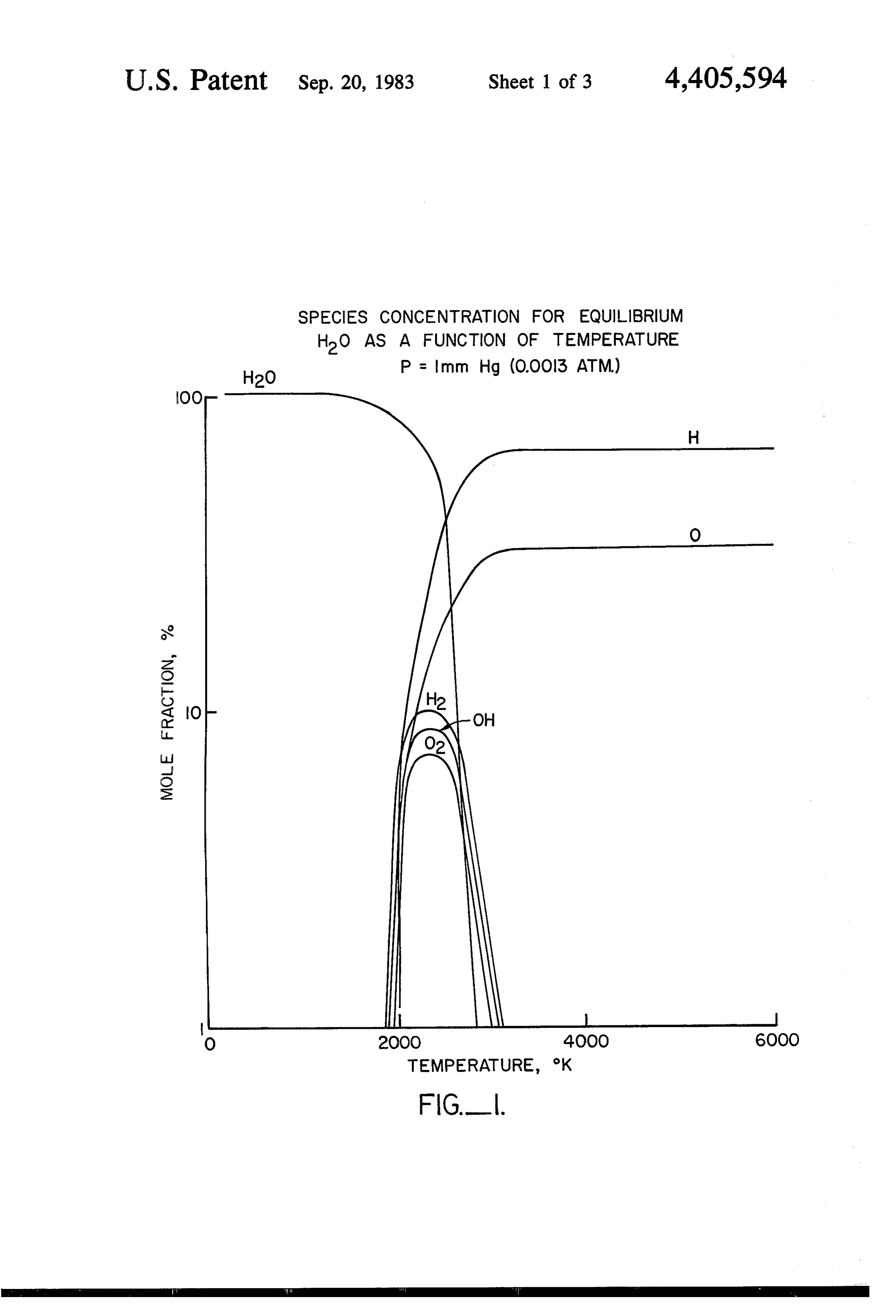
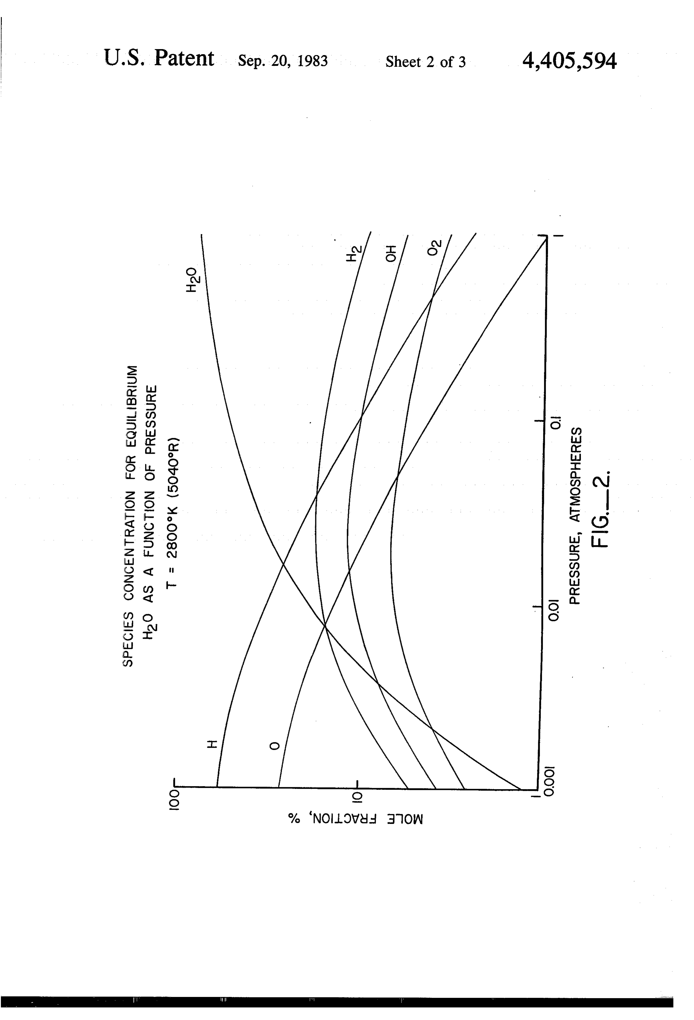
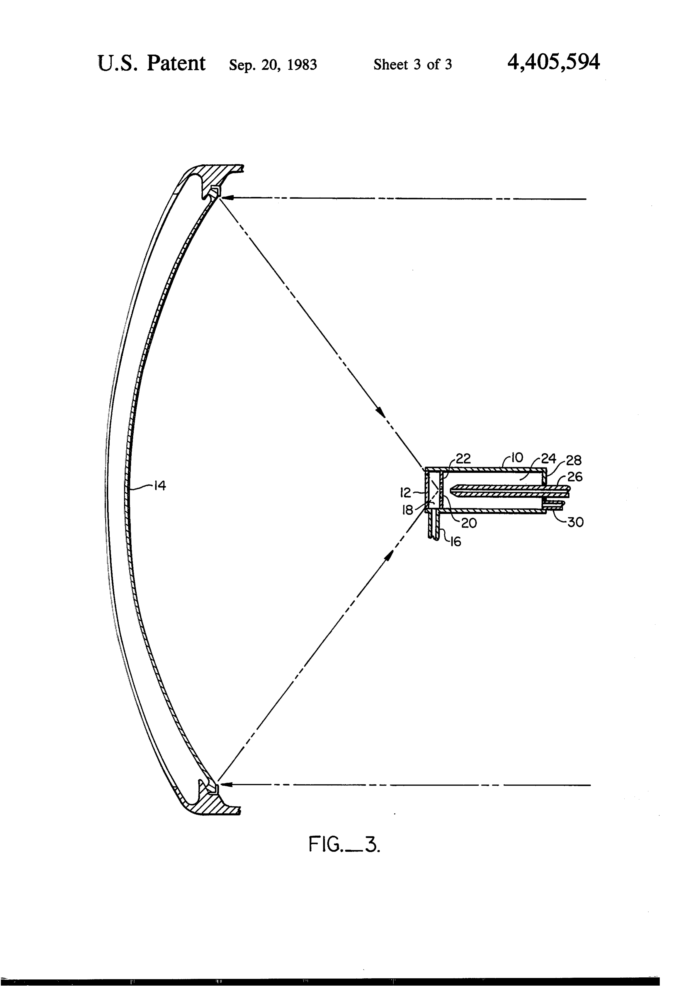
during nighttime posses a problem. Partial solutions to Deterring recombination of the thermal dissociation the problem have included heating various masses to 25 products may be achieved by permitting the heated increase their thermal energy content by temperature products to expand and cool in passing through the increases, phase changes or reversible chemical reac orifice. If the gases achieve supersonic flow, the prod tions. Such systems, however, suffer numerous draw ucts may also be separated in streams according to their backs due to the low quality heat involved, the means of relative molecular weight with a beam skimmer or energy retrieval, and system degradation. On the other 30 separatory baffle located downstream from the orifice. hand, if water is decomposed into hydrogen and oxy gen, a valuable clean burning fuel is produced over DESCRIPTION OF THE DRAWINGS comes many problems of the prior art. FIG. 1 is a graph of species concentration for equilib This approach has been advocated by various con rium H2O as a function of temperature.
tributors in the field. U.S. Pat No. 4,030,890, issued June FIG. 2 is a graph of species concentration for equilib 21, 1977, to Richard E. Diggs, for example, teaches 35 rium H2O as a function of pressure. using a parabolic reflector to concentrate solar radiation FIG. 3 depicts apparatus suitable for practicing one to thermally dissociate steam into hydrogen and oxy embodiment of the invention. gen. Separation of the respective components is achieved by passing the components through a spiral DETAILED DESCRIPTION OF THE housing to separate the heavier components from the 40 INVENTION lighter components. Solar energy concentrators, such as parabolic reflec
ward A. Fletcher, also discloses a system for producing tors, cules.
may be used to thermally dissociate water mole
A graph of the resulting components as a function and separating hydrogen and oxygen from water. In of temperature is shown in FIG. 1 of the drawings. As this system the water is thermally dissociated by con 45 shown in the figure, water begins to dissociate at tem centrated solar energy, and separation is achieved by permitting the hydrogen to preferentially diffuse peratures of less than 2000 Kelvin and is completely dissociated into monatomic hydrogen and oxygen at a through the walls of a permeable housing. temperature of about 3200' Kelvin. Diatomic hydrogen Both of the above inventions suffer, however, from and numerous defects. The most readily apparent problem riumoxygen,
with as well as hydroxyl groups, exist in equilib the components of dissociation at intermedi which is common to both systems resides in the fact that ate temperatures. In accordance with LeChatelier's the water must be contained in a heat-conductive hous ing upon which the energy is focussed that is capable of combined species, and FIG.favor principle, higher pressures the formation of the 2 charts the equilibrium withstanding the intense heat required for the thermal species concentration as a function of pressure at a tem dissociation. At temperatures in the range 1800' to 55 3500 Kelvin, finding suitable materials for gas-tight perature of 2800 Kelvin.
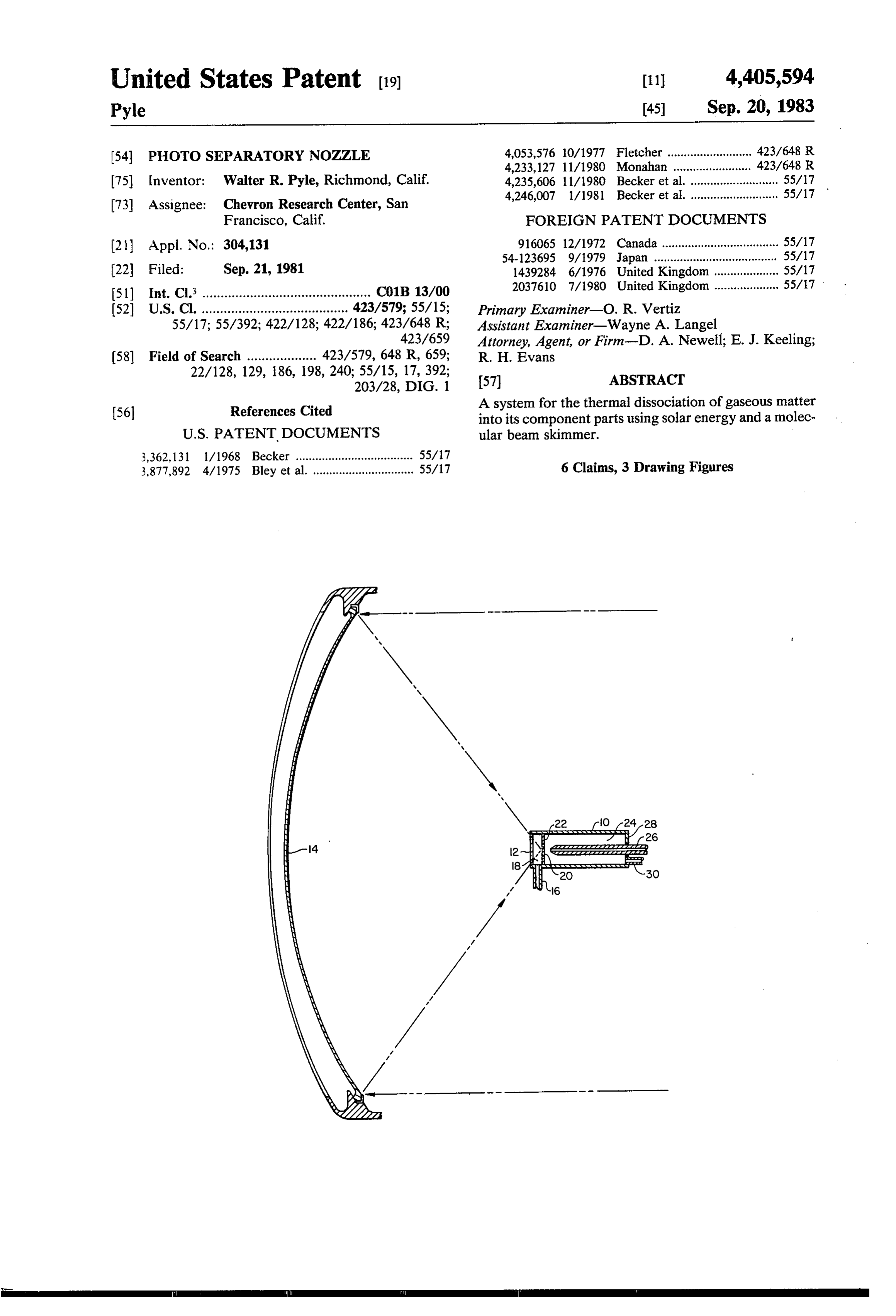
FIG. 3 of the drawings depicts apparatus which is housing or housing of specific permeability is difficult.
A second common problem results from the lack of suitable for practicing the present invention. As shown means to quickly prevent recombination of the sepa ing therein, and as discussed in greater detail below, a hous rated components. 60 10, having a transparent cover 12 is provided in The present invention avoids these problems and combination with a parabolic reflector 14. Inlet port 16 achieves the desired separation in a unique and novel is provided in housing 10 for the introduction of water ae. vapor to the interior of a first chamber 18 in the hous ing. A ceramic orifice 20 is located in an intermediate
SUMMARY OF THE INVENTION 65 wall 22 of the housing near the focal point of the reflec In accordance with the present invention, method tor, and provides an exit for the effluent thermal dissoci and means are provided for the thermal decomposition ation products and any unconverted water vapor from and recovery of the components or composites from chamber 18. Effluent from the housing 10 passes
Page 6
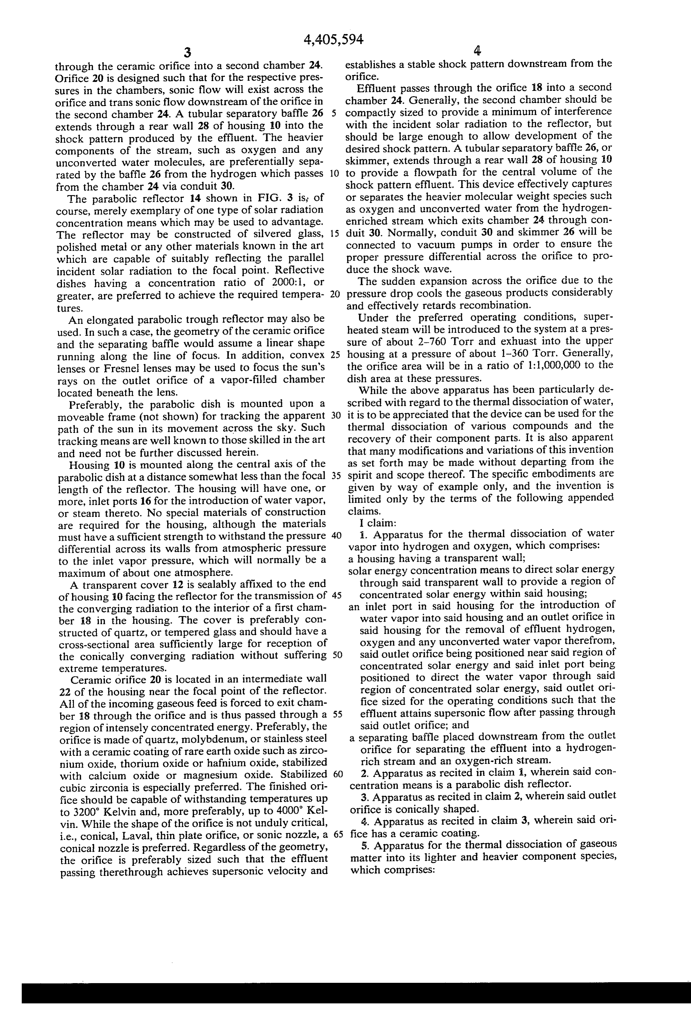
through the ceramic orifice into a second chamber 24. establishes a stable shock pattern downstream from the Orifice 20 is designed such that for the respective pres orifice.
sures in the chambers, sonic flow will exist across the Effluent passes through the orifice 18 into a second orifice and transsonic flow downstream of the orifice in chamber 24. Generally, the second chamber should be the second chamber 24. A tubular separatory baffle 26 compactly sized to provide a minimum of interference extends through a rear wall 28 of housing 10 into the with the incident solar radiation to the reflector, but shock pattern produced by the effluent. The heavier should be large enough to allow development of the components of the stream, such as oxygen and any desired shock pattern. A tubular separatory baffle 26, or unconverted water molecules, are preferentially sepa skimmer, extends through a rear wall 28 of housing 10 rated by the baffle 26 from the hydrogen which passes 10 to provide a flowpath for the central volume of the from the chamber 24 via conduit 30. shock pattern effluent. This device effectively captures The parabolic reflector 14 shown in FIG. 3 is of or separates the heavier molecular weight species such course, merely exemplary of one type of solar radiation as oxygen and unconverted water from the hydrogen concentration means which may be used to advantage. enriched stream which exits chamber 24 through con The reflector may be constructed of silvered glass, 15 duit 30. Normally, conduit 30 and skimmer 26 will be polished metal or any other materials known in the art connected to vacuum pumps in order to ensure the which are capable of suitably reflecting the parallel proper pressure differential across the orifice to pro incident solar radiation to the focal point. Reflective duce the shock wave.
dishes having a concentration ratio of 2000:1, or The sudden expansion across the orifice due to the greater, are preferred to achieve the required tempera 20 pressure drop cools the gaseous products considerably tures. and effectively retards recombination. An elongated parabolic trough reflector may also be Under the preferred operating conditions, super used. In such a case, the geometry of the ceramic orifice heated steam will be introduced to the system at a pres and the separating baffle would assume a linear shape sure of about 2-760 Torr and exhuast into the upper running along the line of focus. In addition, convex 25 housing at a pressure of about 1-360 Torr. Generally, lenses or Fresnel lenses may be used to focus the sun's the orifice area will be in a ratio of 1:1,000,000 to the rays on the outlet orifice of a vapor-filled chamber dish area at these pressures.
located beneath the lens. While the above apparatus has been particularly de Preferably, the parabolic dish is mounted upon a scribed with regard to the thermal dissociation of water, moveable frame (not shown) for tracking the apparent 30 it is to be appreciated that the device can be used for the path of the sun in its movement across the sky. Such thermal dissociation of various compounds and the tracking means are well known to those skilled in the art recovery of their component parts. It is also apparent and need not be further discussed herein. that many modifications and variations of this invention Housing 10 is mounted along the central axis of the as set forth may be made without departing from the parabolic dish at a distance somewhat less than the focal 35 spirit and scope thereof. The specific embodiments are length of the reflector. The housing will have one, or given by way of example only, and the invention is more, inlet ports 16 for the introduction of water vapor, limited only by the terms of the following appended or steam thereto. No special materials of construction claims.
are required for the housing, although the materials I claim:
must have a sufficient strength to withstand the pressure 40 1. Apparatus for the thermal dissociation of water differential across its walls from atmospheric pressure vapor into hydrogen and oxygen, which comprises: to the inlet vapor pressure, which will normally be a a housing having a transparent wall;
maximum of about one atmosphere. solar energy concentration means to direct solar energy A transparent cover 12 is sealably affixed to the end through said transparent wall to provide a region of of housing 10 facing the reflector for the transmission of 45 concentrated solar energy within said housing: the converging radiation to the interior of a first cham an inlet port in said housing for the introduction of ber 18 in the housing. The cover is preferably con water vapor into said housing and an outlet orifice in structed of quartz, or tempered glass and should have a said housing for the removal of effluent hydrogen, cross-sectional area sufficiently large for reception of oxygen and any unconverted water vapor therefron, the conically converging radiation without suffering 50 said outlet orifice being positioned near said region of extreme temperatures. concentrated solar energy and said inlet port being Ceramic orifice 20 is located in an intermediate wall positioned to direct the water vapor through said 22 of the housing near the focal point of the reflector. region of concentrated solar energy, said outlet ori All of the incoming gaseous feed is forced to exit cham fice sized for the operating conditions such that the ber 18 through the orifice and is thus passed through a 55 effluent attains supersonic flow after passing through region of intensely concentrated energy. Preferably, the said outlet orifice; and orifice is made of quartz, molybdenum, or stainless steel a separating baffle placed downstream from the outlet with a ceramic coating of rare earth oxide such as zirco orifice for separating the effluent into a hydrogen nium oxide, thorium oxide or hafnium oxide, stabilized rich stream and an oxygen-rich stream. with calcium oxide or magnesium oxide. Stabilized 60 2. Apparatus as recited in claim i, wherein said con cubic zirconia is especially preferred. The finished ori centration means is a parabolic dish reflector. fice should be capable of withstanding temperatures up 3. Apparatus as recited in claim 2, wherein said outlet to 3200' Kelvin and, more preferably, up to 4000 Kel orifice is conically shaped.
vin. While the shape of the orifice is not unduly critical, 4. Apparatus as recited in claim 3, wherein said ori i.e., conical, Laval, thin plate orifice, or sonic nozzle, a 65 fice has a ceramic coating.
conical nozzle is preferred. Regardless of the geometry, 5. Apparatus for the thermal dissociation of gaseous the orifice is preferably sized such that the effluent matter into its lighter and heavier component species, passing therethrough achieves supersonic velocity and which comprises:
Page 7
a housing having a transparent wall; 6. A method for thermally dissociating water vapor a solar energy concentration means to direct solar en into hydrogen and oxygen, comprising: ergy through said transparent wall to provide a re introducing water vapor into a chamber at a first pres gion of concentrated solar energy within said hous sure between about 2 and 760 Torr; ing; 5 heating said water vapor to thermally dissociate at least an inlet port in said housing for the introduction of a portion thereof into hydrogen and oxygen with gaseous matter into said housing and an outlet orifice concentrated solar energy;
in said housing for the removal of effluent component passing said hydrogen and oxygen and unconverted water vapor through an orifice at a second pressure species therefrom, said outlet orifice being positioned near said region of concentrated solar energy and said 10 between about 1 and 360 Torr, to produce a super inlet port being positioned to direct the gaseous mat sonic molecular jet of hydrogen, oxygen and uncon ter through said region of concentrated solar energy, verted water vapor, to produce a shock wave down said outlet orifice sized for the operating conditions stream of said orifice, to rapidly cool said hydrogen, such that the effluent attains supersonic flow after oxygen and unconverted water vapor and to retard passing through said outlet orifice; and 15 recombination of same; and a separating baffle placed downstream from said outlet separating said jet in said shock wave into a hydrogen orifice for separating the effluent into a heavier com rich stream and an oxygen-rich stream with a beam ponent-rich stream and a lighter component-rich skimmer.
Stream.
Provenance
- Collection
- Cited prior art
- Original PDF
- patentimages.storage.googleapis.com →
- Filed
- 1981-09-21
- Pages
- 7
- Method
- pdftotext (the PDF's own text layer) + pdftoppm 300dpi page scans
- Source
- Google Patents bibliographic record
- Granted
- 1983-09-20
- Inventors
- Walter R. Pyle; Chevron Research and Technology Co
- Transcribed from
- patentimages.storage.googleapis.com →