patent · US4405010
Sensible heat storage unit
20 September 1983
Page 1 — bibliographic record
United States Patent (19) 11) 4,405,010 Schwartz, (45) Sep. 20, 1983 54 SENSIBLE HEAT STORAGE UNIT 3,203,472 8/1965 Brandt ................................... 165/10 3,320,044 5/1967 Cole et al. ... ... 165A X 75 Inventor: Jacob Schwartz, Arlington, Mass. 3,397,738 8/1968 Daunt .................................... 165/10 3,477,496 11/1969 Becker .... ... 165/10 73 Assignee: Sanders Associates, Inc., Nashua,
N.H. FOREIGN PATENT DOCUMENTS 21 Appl. No.: 157,930 812491 4/1959 United Kingdom .................. 165/10 22) Filed: Jun. 9, 1980 Primary Examiner-Albert W. Davis, Jr. Attorney, Agent, or Firm-Louis Etlinger; Richard I.
Related U.S. Application Data Seligman 63) Continuation of Ser. No. 98,889, Jun. 28, 1978, aban 57 ABSTRACT doned.
A sensibe heat storage unit is provided which has a 51 Int. Cl. ....... a w8 as a F28D 17/00 "step function' thermal gradient, and is constructed so (52) U.S. C. ............ . 165/4; 165/10 as to have alternated regions of different thermal con 58 Field of Search ...................................... 165/4, 10 ductivity along the flow path through the unit such References Cited that, in one embodiment, there are spaced elements 56) within the storage unit having transverse conductivities
655,274 8/1900 Ramsden .......................... 165/10 X spaces therebetween. This permits discharge of the 2,492,788 12/1949, Dennis .................................... 165/4 storage unit at a uniform temperature until the storage 2,616,668 11/1952 Van Weenen et al. ............... 65/10 unit is emptied.
2,706,109 4/1955 Odman .................. 165/10 X 3,112,184 11/1963 Hollenbach ....................... 165/10 X 5 Claims, 4 Drawing Figures
CESaty
Nala
Page 2
Drawing sheet — no readable text.
Page 3
Drawing sheet — no readable text.
Page 4
electric generator. In the solar energy receiver loop a
SENSIBLE HEAT STORAGE UNIT switchable sensible heat storage unit is charged by the solar receiver. The charged storage unit is then
This is a continuation of application Ser. No. 918,889, switched into the Brayton cycle turbine loop where it filed June 28, 1978, now abandoned. - serves as the prime energy source of the engine. Finally, FIELD OF INVENTION after it has been discharged, the unit may be utilized as a high temperature, high efficiency recuperator to re
This invention relates to energy conversion systems cover waste heat from Brayton cycle turbine, exhaust. and more particularly either to an improved sensible The switchable sensible heat storage unit system is alter heat storage unit which can be discharged at a uniform 10 natively referred to as an "energy shift register' system. temperature. The use of the sensible heat storage unit as a recuper BACKGROUND OF THE INVENTION ator permits the Brayton cycle engine to be run at ex tremely low pressure ratios and a thermal/electric con
While the subject invention relates to an improved version efficiency in excess of 60%. This can result in a sensible heat storage unit, it has particular utility in solar 15 solar/electric conversion efficiency in excess of 40%, as energy conversion systems, and especially those which contrasted with steam cycle solar energy conversion use Brayton cycle engines. It is therefore useful to de efficients of less than 20%. scribe the solar energy conversion system for which the In the conventional Brayton cycle, large pressure subject unit was designed. Although designed for a losses occur in the heat addition cycle because heat is special type of solar energy conversion system, the 20 being added to a high velocity fluid stream. Also, penal Subject storage unit may be utilized in any application izing temperature and pressure losses occur in the large where constant discharge temperatures are required. recuperator needed to make low pressure ratio engines With respect to solar energy conversion systems, operate at high thermal efficiencies. In some types of while "latent' heat switchable storage units have been ceramic wheel heat exchangers, there is significant leak utilized in steam cycle solar energy conversion systems 25 age to further penalize performance. as illustrated in U.S. Pat. No. 2,933,855 issued to E. K. The "energy shift register' system utilizing sensible Benedek et al., Apr. 26, 1960, the benefits of a "sensible' heat storage improves the efficiency of Brayton engines heat storage system have heretofore not been utilized by minimizing these losses. Heat addition occurs effi with a Brayton cycle system involving a gas cycle tur ciently and slowly without significant pressure loss in a bine. 30 large insulated tank filled in one embodiment with alter One of the major problems with solar energy conver nated materials of different thermal conductivity which sion systems utilizing steam is, in general, the extremely produce low conductivity in the flow direction. In one corrosive nature of superheated steam and the upper embodiment the storage unit is formed by spaced ce temperature limit associated with the tubing or plumb ramic matrices or perforated ceramic elements. As the ing used. In general, it is possible to heat up solar receiv 35 air passes through the matrices at velocities of 1 m/sec ers to temperatures in excess of 2500' F. in situations or less, a sharp thermocline (called herein a "step func utilizing a central receiver positioned at the focus of a tion' thermal gradient) develops; i.e., in a narrow re mirror field which redirects sunlight onto the solar gion of the tank a major temperature gradient develops, energy receiver. Thus, the capability of central receiver and travels at approximately 1/1000 of the air velocity. type installations far exceeds the restraints on super 40 As will be seen, this permits discharge of the tank at a heated steam systems which, in general, must operate uniform temperature. When the step function thermal below 100 F. gradient reaches either the top or bottom of the tank, It will be appreciated that even the highest quality the tank is considered full and must be switched out of steels have limited strength at temperatures over 1650 one position of the Brayton cycle into another. Hence, F. and, therefore, new types of solar receivers and stor 45 the name "energy shift register." age equipment are necessary if solar energy is to be As can be seen, the sensible heat storage is utilized to efficiently converted into electrical energy. It will be isolate the receiver loop from the engine or electric appreciated that the higher the temperature of the power generating loop. Thus, the sensible heat storage working fluid or gas, the more efficient will be the unit provides a large buffer for the turbine and allows a conversion process. 50 high degree of flexibility in plant operation by allowing In the present illustration an air or Brayton cycle different rates of thermal energy collection and con system is used instead of a steam cycle. Brayton cycle sumption, engines have the advantages of proven outstanding In short, the isolation between the receiving loop and realibility and efficiencies 10-20% higher than the the engine loop buffers the engine against changes in steam cycle engines. As will be seen, they integrate well 55 solar flux due to the passing of clouds over the sun, etc., with low cost sensible heat storage units, and become or from any receiver-related condition. Thus, the en optimum at very low pressure ratios, which allows even gine loop can be made and designed to run at maximum higher reliabilities and high component efficiencies. efficiency regardless of the operating conditions in the The solar energy conversion system described can receiver loop.
withstand the high temperatures associated with central 60 Moreover, because of the isolation between the re receiver type installations in which the receiver may be ceiving loop and the engine loop in the subject inven of the type that utilizes a ceramic honeycomb heat ex tion, the solar receiver loop may operate at a different changer and in which sensible heat storage units of pressure than the engine loop, since the storage unit to refractory materials are used so as to withstand the high be described can be discharged at any desired pressure. temperatures. 65 Separating the receiver from the pressurized engine In one embodiment, an efficient "split cycle' solar loop permits the use of an "open-ended' ambient pres energy system includes a solar energy loop isolated sure solar receiver in which a "window' need not be from a Brayton cycle engine (turbine) coupled to an used. The "open-ended' receiver typically operates at
Page 5
ambient pressure to reduce sealing requirements and for efflux of the furnace is piped into another "cold' stove safety and low cost. This receiver also uses air which is where heat is extracted for use during the next blast a non-polluting working fluid. Moreover, when work period.
ing at atmospheric pressure, the heat exchanger in the In a typical installation, a furnace will have three or receiver may be assembled loosely to its housing to four stoves manifolded together with automatic valves, allow room for thermally induced motions. with multiple stoves "on blast.” The outputs of these While a split cycle solar energy conversion system stoves are controlled by heat sensors and valving so that with sensible heat storage has been described in which the combined output temperature from the manifolded a Brayton cycle engine is utilized, it will be seen that the stoves remains constant. It should be noted that the subject system involves improvements in the Brayton 10 output temperature of these stoves varies with time cycle system itself. The improvements to the Brayton during the discharge cycle and, therefore, it is necessary cycle system include the use of a sensible heat storage to add and subtract heat as necessary depending on the unit both for recuperation and as a prime energy source. sensed temperature of the air delivered to the blast As a prime energy source, operating the storage unit furnace. Through an arrangement called staggered par at low pressure makes it possible to run the Brayton 15 allel operation the stoves are valved from one position cycle engine at highly efficient low pressure ratios. to another to maintain constant output temperatures Moreover, energy for the Brayton cycle engine may be during the continuous operation of the furnace. provided not only from the sun, but also from extremely The ideal operating temperature for current blast "dirty' fuels. This is because deposits from the fuels are furnace stoves is 2000 F. which has now been found to not picked up by the low velocity gaseous working fluid 20 be ideal for efficient gas turbine operation. It has also and do not reach the Brayton turbine blades to corrode been found that typical stoves deliver air at the same them. pressure as that required if the stove were to exhaust When the sensible heat storage unit is used as a recu into a turbine designed for recuperated operation. Addi perator, because of its extremely high effectiveness, the tionally, since blast furnace stoves are designed to han entire efficiency of the Brayton cycle system is signifi 25 dle large flow rates with low internal pressure losses, cantly increased. high Brayton cycle efficiency and thus, high thermal/electric conversion efficiencies can be maintained.
SENSIBLE HEAT STORAGE In summary, it has been found that the adaptation of It should be noted that the storage unit envisioned for blast furnace stoves to Brayton cycle power plants is use herein is a "sensible' heat storage unit as distin 30 unusually efficacious because of the ability to store and guished from a "latent' heat storage unit. The distinc release huge quantities of heat at high temperatures; tion between sensible heat storage and latent heat stor because of the ability to deliver large air flows; because age is that sensible heat is energy stored in the heat of the ability to operate at the desired pressure levels; capacity of the materials in the storage unit so that and because of the existence of automatic valving tech every time a BTU of sensible heat is stored, the temper 35 niques to rapidly connect and reconnect stoves. ature of the material goes up proportionately. Thus, STEP FUNCTION THERMAL GRADIENT with every BTU added, the temperature of the material STORAGE goes up, whereas in latent heat storage, there is a phase change in the material such that for every BTU added However, one problem with the use of the traditional there is not necessarily any temperature change, but blast furnace stove is that the outlet temperature drops rather part of the material changes state, e.g., goes from 400-500 F. during discharge, an undesirable condition liquid to gas or solid to liquid. In latent heat storage for operating Brayton cycle machinery because it there is no change in temperature until all the material means either a loss in efficiency or that makeup heat has experienced a phase change. It should be noted that must be provided.
the above-mentioned Benedek et al steam cycle plant 45 As will be seen hereinafter, it is not desirable to mani utilizes latent heat storage. The major problem with fold and control numerous individual stoves, it is desir latent heat storage is the corrosive nature of the phase able to provide a novel sensible heat storage unit in change materials used. In the Benedek et al. patent which the above temperature drops are not experi sodium salt (NaNO3) which is exceedingly corrosive is enced. This unit is called a step function thermal gradi used as the phase-change material. Also the temperature 50 ent storage unit. The term "step function' refers to a is fixed for a given phase change material, which limits sharp temperature discontinuity between a "spent” re the temperature change over which latent heat storage gion of the unit and a "charged' region of the unit. In units may operate. other words, the temperature discontinuity is confined Sensible heat storage has been utilized in the steel to a narrow region of the unit, typically a region 1/10 industry for over 150 years through the use of what are 55 the length of the unit. Because of the "step function' known as blast furnace stoves. A blast furnace stove is operation, this sensible heat recovery unit is character a heat exchange device used since the early 1800's in the ized by a constant output temperature at temperatures glass and steel industries. In general, it consists of an in excess of 2000' F. and makes possible efficient engine insulated pressure shell containing an internal air duct design.
and a large array of refractory bricks called "checkers.' For purposes of this portion of the invention, step The checkers are arranged in stacks, often 30 meters function thermal gradient storage units are character high, forming a large number of individual air passages ized in that they have an overall anisotropy in that there called flues, through which the air can flow. Heat is is a low thermal conductivity in the flow direction as alternately stored in the checkers or removed from opposed to the lateral direction. In one embodiment, them during opposing portions of the process cycle. In 65 this is accomplished by spacing isotropic ceramic matri the steel industry, these stoves are used to supply vast ces along the flow path within the storage unit. In gen quantities of hot air into the blast furnaces which are eral, this results in a structure in which the spaced apart charged with iron ore, coke, and limestone. The hot matrices or elements have a higher intrinsic as well as
Page 6
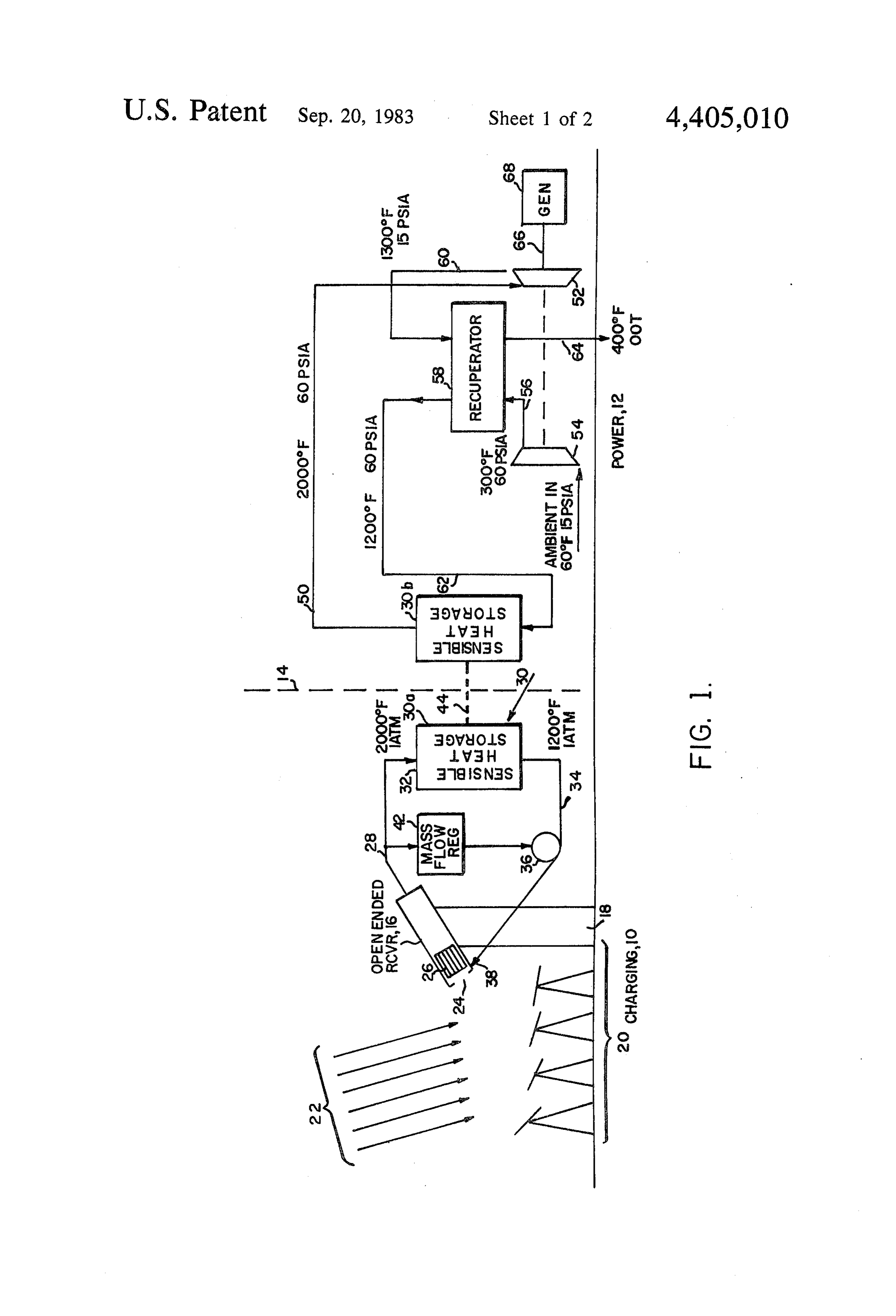
overall transverseconductivity than the conductivity of system 36 which exhausts to the front end of the solar the material in between the elements, while the net receiver as shown by return line 38. longitudinal conductivity is lower than the matrix or In operation, air is sucked from return line 38 and is the interstitial material due to the alternating "series” heated as it passes through heat exchanger 26 which is arrangement. This results in a battery-like operation of 5 heated by the focused solar radiation (called "insola the storage unit, such that until the storage unit is com tion') from the mirror field. With proper pressure ad pletely discharged, the output temperature of the fluid justments, the pressure drop across the open end 24 of from the storage unit stays constant. This is because the receiver can be reduced to zero thereby eliminating there is a sharp "step function' differential in tempera the need for a window. The hot air downstream of the ture within the storage unit as energy is withdrawn 10 heat exchanger is coupled to the inlet of the sensible from or added to the unit. The sharp temperature heat storage which initially is at 1200' F. change takes place in a narrow region of the unit and The sensible heat storage unit at 30a is charged to travels from the inlet end of the storage unit towards the capacity by the incoming hot air such that at some time outlet end during the discharge operation. Prior to the after the charging has begun, the entire sensible heat step function thermal gradient reaching the output port storage unit is at 2000F. The flow through the sensible heat storage unit is adjusted by a mass flow regulator 42 of the storage unit, energy is taken out of the storage which unit at essentially a constant temperature. In essence, accordance adjusts the mass flow of blowing system 36 in therefore, the storage unit can be conceived of as a tain the receiver with the sensed temperature so as to main battery whose output does not vary during the dis 20 When the sensible outlet air temperature at 2000' F. charge cycle until the battery is completely discharged. to capacity, it is shiftedheat storage unit at 30a is charged by conventional valving tech
It is, therefore, an object of this invention to provide niques from its position shown a step function thermal gradient storage unit for utiliza to the left of dotted line tion in an energy conversion system. 14 to the position 30b to the right of dotted line 14 as illustrated by arrow 44. In the position illustrated by
It is another object of this invention to provide a 25 30b, the sensible heat storage unit acts as a prime source sensible heat storage unit with preferred anisotropic of energy for the power loop.
properties. In the illustrated case, the sensible heat storage unit at These and other objects will be better understood in view of the following detailed description when viewed position 30b, is discharged at 60 psia and at a tempera ture of 2000' F. over line 50 to the turbine section 52 of in light of the accompanying drawings in which: 30 a Brayton cycle engine. The engine includes a compres BRIEF DESCRIPTION OF THE DRAWINGS sor 54 which compresses ambient air at 60' F. and 15 psia to raise the temperature of the incoming air to 300
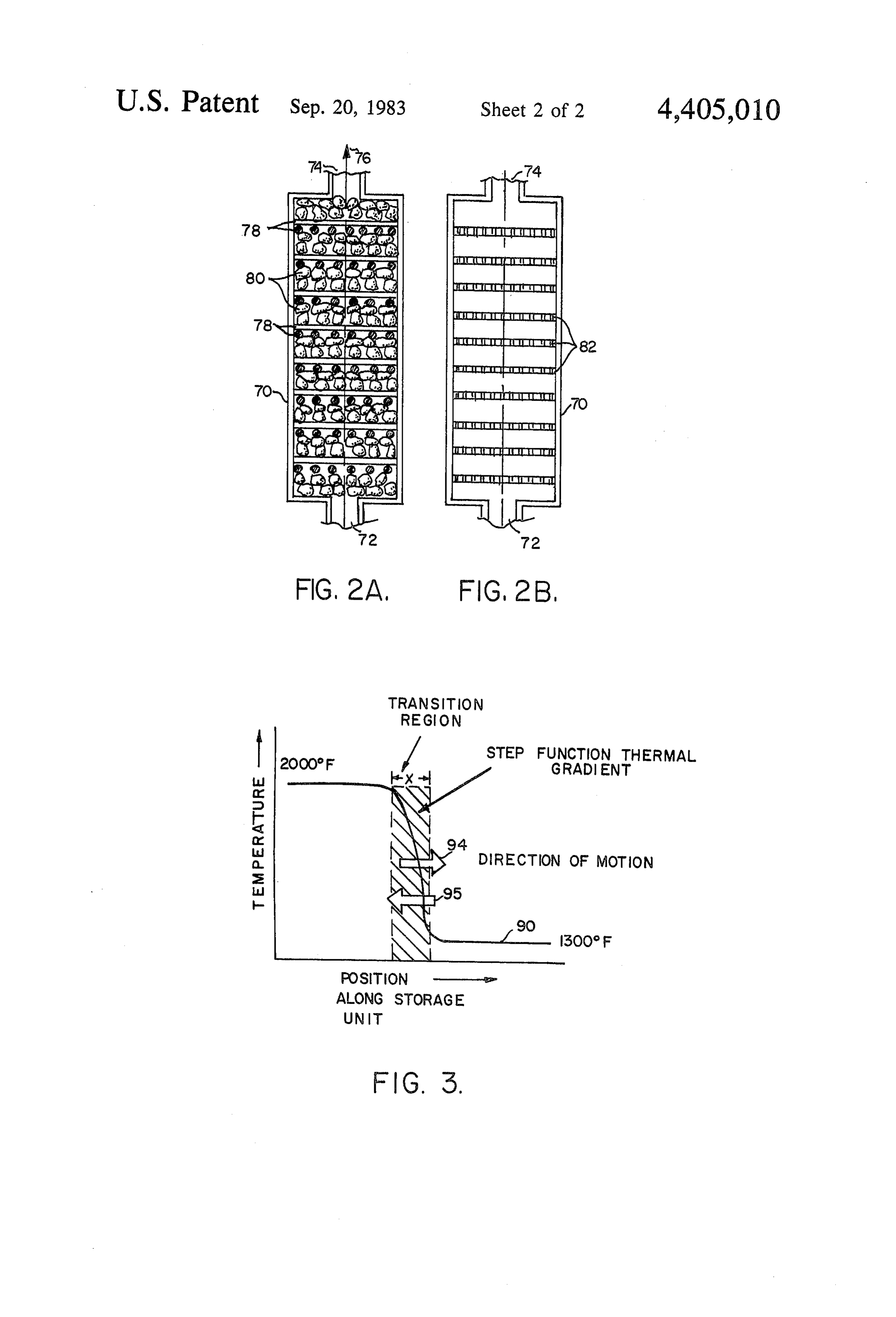
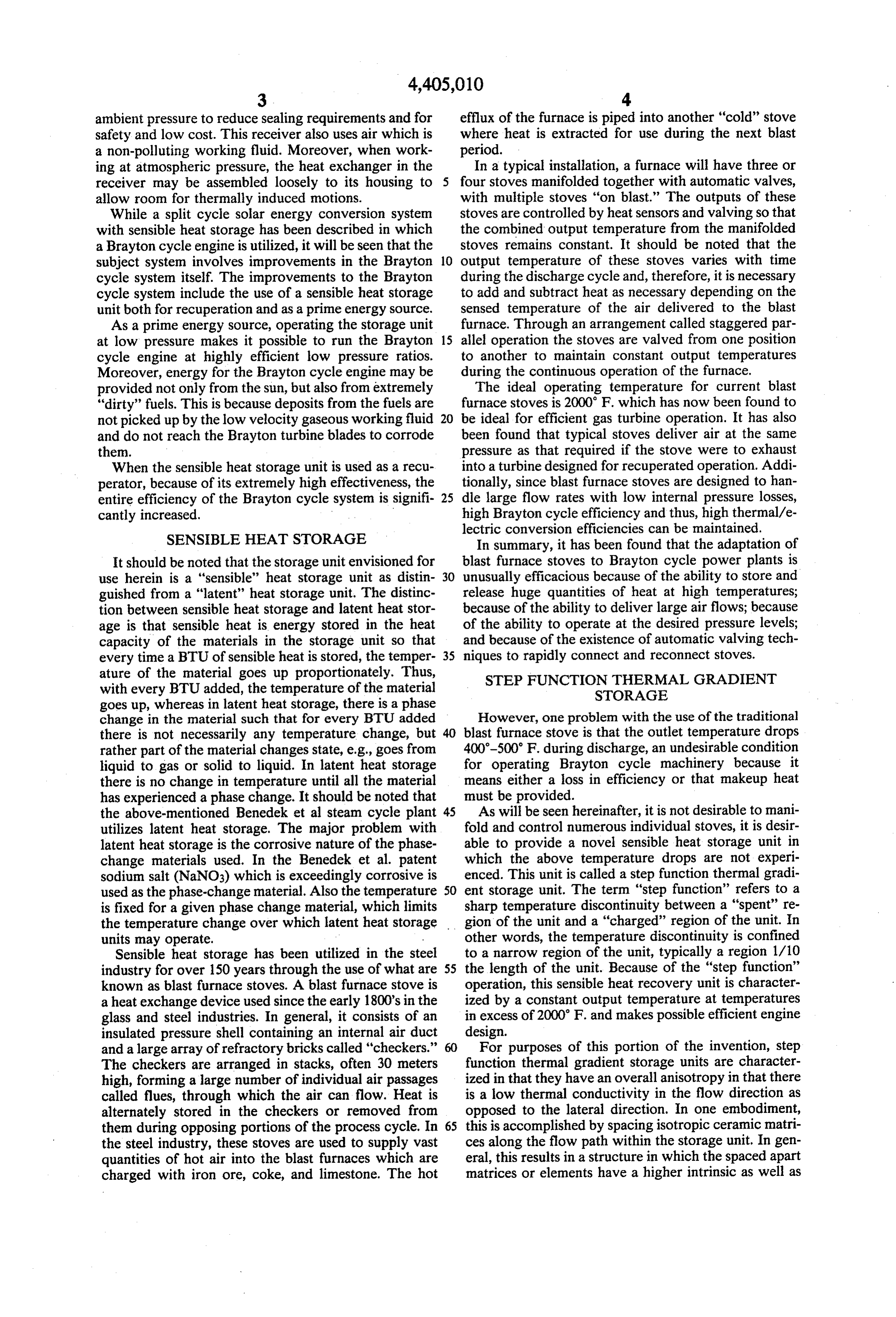
FIG. 1 is a diagrammatic illustration of an isolated F. and to raise the pressure to 60 psia. The output of the loop thermal/electric conversion system in which the compressor at 56 is connected to a conventional recu charging loop includes an open-ended solar receiver 35 perator 58. At this point, the 300" F. air from the com and in which the engine loop includes a Brayton cycle pressor section captures waste heat from the output of engine; turbine section 52 via line 60 which is coupled to recu FIGS. 2A and 2B diagrammatically illustrate in perator 58. This line carries air at 15 psia at 1300" F. In cross-section step function thermal gradient storage the process, the temperature of the air from the com units which may be utilized as the sensible heat storage pression section goes from 300' F. to 1200 F. and is units illustrated in FIG. 1; and delivered over line 62 to the input end of the sensible FIG. 3 is a graph illustrating the "step function' heat storage unit at position 30b. When the unit at 30b is characteristic of the step function thermal gradient stor discharged from 2000' F. to 1200 F., it is switched back age units of FIG. 2, showing the direction and motion to position 30a for recharging.
of the thermal gradient during either the charging or 45 It should be noted that the output 64 of the recupera discharging cycle. tor corresponding to input line 60 exhausts air to the DETAILED DESCRIPTION atmosphere at approximately 400 F.
As shown, the mechanical turbine output is illustrated
Referring now to FIG. 1, in one embodiment, the by dotted line 66 and is coupled to a conventional elec illustrated system includes a charging loop generally 50 tric generator 68.
designated by reference character 10 and a power loop The advantage provided by the system of FIG. 1 is generally designated by reference character 12, sepa the ability to separate the solar collection cycle from the rated by dotted line 14. An open-ended solar receiver turbine cycle of using highly efficient sensible heat stor 16, in one embodiment, is located in the charging loop age. Operationally, this offers the user the advantage of and is mounted on a tower 18 which is at the focus of a 55 scheduling power outputs to meet demand without mirror field generally indicated at 20. Mirror field 20 direct dependence upon instantaneous availability of redirects solar rays 22 through the open-end 24 of the focused sunlight. As mentioned hereinbefore, sensible solar receiver and onto a heat exchanger 26 located heat storage in the form of checker stoves may, if prop within the receiver. The heat exchanger may be a ce erly manifolded, be utilized. Single sensible heat storage ramic honeycomb matrix made of silicon carbide. In units may also be used, especially if modified for step one embodiment, this open-ended receiver operates at function thermal gradient operation.
atmospheric pressure" so that its output over line 28 In the illustrated system, all energy passes through a carries air at 2000' F. and 1 atm. to a sensible heat stor storage unit. This provides a large buffer for the turbine age unit 30 at position 30a. The input to the sensible as the only storage losses are those associated with heat storage unit at 30a is designated 32, and its output 65 insulation losses through the storage unit wall and losses 34. In one embodiment, prior to being completely filled, involved in pressure/switching of the sensible heat stor the sensible heat storage unit is initialized at 1200' F. age units. These sensible heat storage units also provide Output 34 is connected to a suitable fan or blowing a high degree of flexibility in the plant operation by
Page 7
allowing different rates of thermal energy collection Chemical Engineering Transcripts), Vol. MC.1 (#1), at and consumption. page 14, the works of Schumann (Heat Transfer: A Lig By the ability to isolate: the charging loop from the uid Flowing Through a Porous Prism, J. Franklin Inst., power loop, it is now possible to utilize a solar receiver 5 Vol. 208, September, 1929, pp. 405-16) and Furnas which differs from conventional configurations in that (Heat Transfer from a Gas Stream to a Bed of Broken. it does not utilize a standard high pressure-tube/boiler, Solids, Amer. Inst. Chem. Engrs. Transcripts, Vol. 24, ; technique. The open-ended solar receiver captures and June, 1930, pp. 142-69) on packed beds indicate that, transfers heat at pressures near atmospheric, utilizing a . there is an assumption that the bed, has zero.conductiv material and a configuration that is a highly efficient ity in the flow direction and infinite conductivity in absorber of solar radiation. The aforementioned honey- :10, planes normal to.it. However, Close, later on in his comb heat exchanger operates with a very low-pressure article, indicates that these assumptions for the rock pile drop (less than 1 inch H2O) thus reducing the air sealing thermal storage are incorrect because so little is known requirements and permitting the honeycomb compo about the actual operation of rock piles when used as nents of the heat exchanger to be assembled loosely to thermal storage. On page 17 of the Close article Close allow room for thermally-induced, motions. Since, the 5 says that certain factors suggest that the simple theory is entire receiver, operates at near atmospheric pressure, inadequate and that it would be instructive to examine safety hazards and the cost of the pressure vessel are. the validity of the main assumption of zero conductivity minimized. m . . .. . . of the packing in the flow direction and infinite conduc In passing, the open cycle Brayton concept has sev, tivity perpendicular to it. Thus, according to Close, the eral important advantages. The basic gas turbine cycle 20 assumptions by Schumann and Furnas are all subject to is simply implemented compared to steam cycles. The scrutiny and extensive testing. . : . .. . reduced maintenance associated with gas turbines is On the other hand, a computer program and algo enhanced by the reduction of the corrosion problems: rithm have now been developed which evaluate all of due to fuel combustion products. In addition, the en the types of energy transfer within the rock pile on a ergy efficient, open-cycle air, system permits direct re. 25 point-by-point basis. It has been found that, indeed, as jection of residual (waste) heat to the atmosphere, elimi Close suspected, there is not infinite conductivity in nating the need for large quantities of cooling water. planes normal to the flow path, nor is there zero con- : Moreover, the engine can be mounted at the concent. ductivity in the flow direction. . . . " trator focus and closely coupled to the solar receiver. In the subject invention these anisotropic characteris As will be seen, when the recuperator is in the form of 30, tics can be made to occur within the sensible heat stor a sensible heat storage unit, it is lightweight and can also age unit by specialized structure within the unit, and be mounted with the receiver/engine unit, providing an that having done so, the transition zone for the thermal - integrated thermal conversion system with short-piping gradient can be kept small, of the order of 1/10 the and low thermal losses. i . ... . . .. . overall flow path length. This provides a step function In summary, because of the use of the split cycle, an 35 thermal gradient which permits the storage unit to dis-, open-ended receiver can be used which uses air as the charge at a substantially constant temperature until the working fluid. Moreover, heat collection and power. gradient travels from the inlet end of the storage. unit generation is accomplished in separate, independent completely. to the outlet end. . . .
heat transfer loops. Additionally, since the power gen In other words, there is a large thermal gradient be eration system works from storage, it is independent of 40 tween the "charged' portion of the storage unit and the short term fluctuations and solar radiation. Finally, the "spent' or uncharged portion of the unit. Because the use of sensible heat storage units for storage signifi gradient travels from the inlet to the outlet end at a cantly increases system efficiency because it actually relatively low speed, and because the transition is kept fulfills a recuperator/heat exchanger function as well as to a small area, the discharge temperature of the unit is storage/delay. 45. maintained substantially constant throughout the dis In the system illustrated, either one or two storage charge cycle. This type of operation is not possible with units are used which are sequentially valved into one of uniform packed beds operating at the temperatures and the two positions shown. In another type system, a third pressures specified in the above-mentioned articles. and even a fourth unit may be used for additional stor What is therefore necessary is to modify the packed bed age and recuperation. 50. structure to give it an anisotropic property of low ther mal conductivity in the flow direction and higher ther
STEP FUNCTION THERMAL GRADIENT mal conductivity lateral to the flow direction. STORAGE UNIT This anisotropic property results in the step-function As will be seen, it is desirable for the storage unit to thermal gradient and is made to occur in the subject have what is known as a "step function thermal gradi. 55 invention by the alternation or lamination of materials ent” in which the temperature difference between two of different thermal conductivity along the flow path in adjacent locations, is very shape. This means that the the storage unit, or by the use of anisotropic materials in transition between one temperature and another tem: the, storage unit.
perature within the storage unit occurs in a transition In proder to produce a step function thermal gradient, zone of less than 1/10 the total flow path length of the it is desirable to reduce transverse gradients while maxi unit. This is accomplished in one embodiment by pro mizing gradients in the flow direction, with the sharpe viding high density, high heat capacity, high conductiv ness of the thermocline being dependent upon low con ity matrices at spaced locations along the flow path ductivity in the flow direction.Therefore, it is a charac such that, in general, the thermal conductivity in the teristic of the subject storage unit that high conductivity direction of flow is mimimized. . .. . . . ... 65 in the flow direction is materially reduced, thereby to As outlined in an article by D.J. Close entitled, Rock provide a step function thermal gradient. Pile Thermal Storage for Comfort Air Conditioning, In It is possible to produce this step function thermal strumentation Engineering Australia (Mechanics & gradient by using laminated structure made up of iso
Page 8
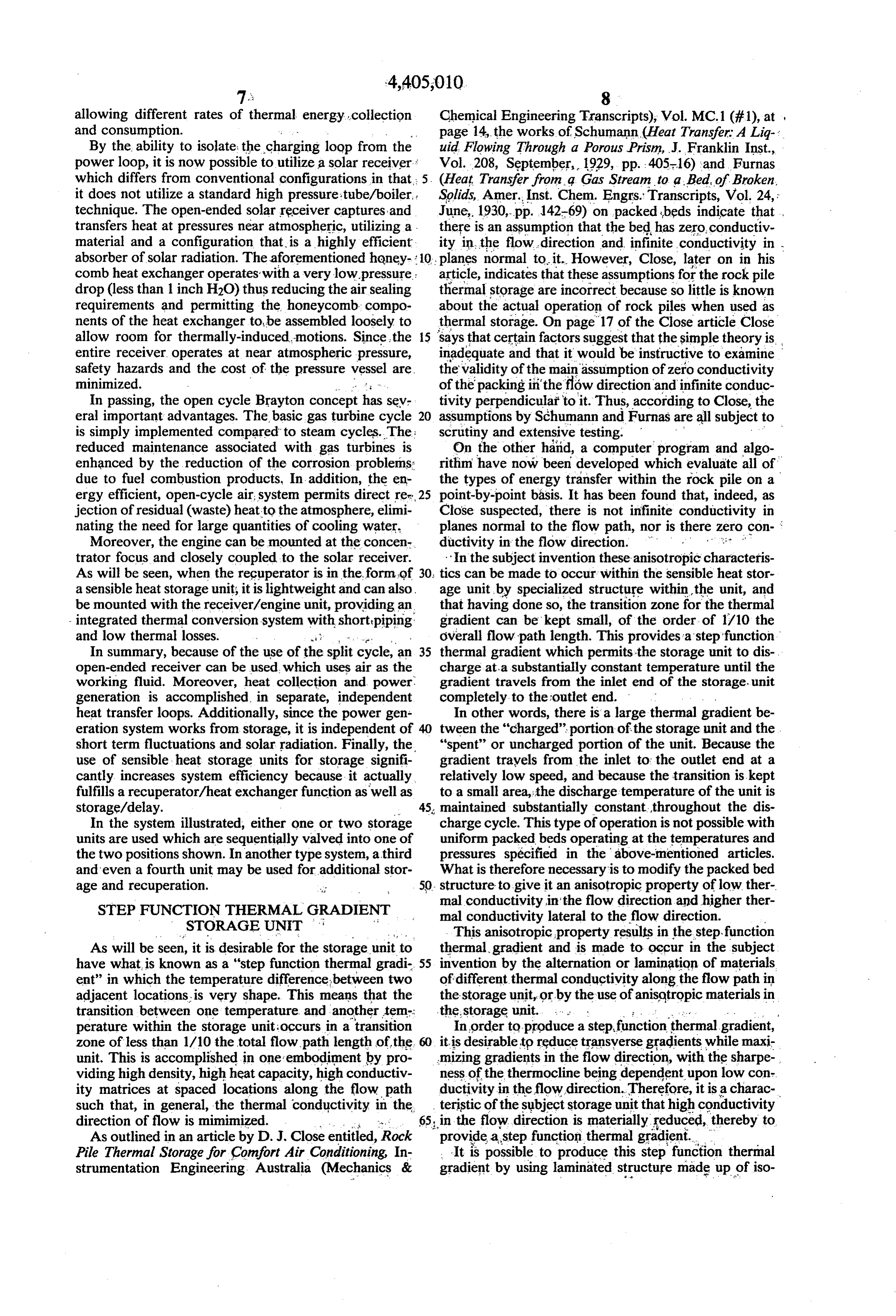
tropic materials. Thus, it is a finding of this invention fact that the transition region between one temperature that isotropic elements may be used to achieve a step and another in the storage unit occupies a distance function thermal gradient of the type described, while along the flow path of less than some small fraction of helping uniformity of heat transfer in the transverse the total flow path distance between the inlet to the direction. storage unit and the outlet. Thus, in one embodiment in It is also a finding of this invention that the step func the charging cycle the temperature in the storage unit tion thermal gradient can be achieved by providing goes from 1300 F. to 2000 F. over a distance of x spaced regions having a conductivity transverse to the which is less than 1/10 the total flow path length flow path which is higher than the conductivity of the through the unit.
material along the flow path in the spaces inbetween O While fraction 1/10 is utilized, for explanation pur these regions. poses, it should be appreciated that the step function It will be appreciated that the anisotropy in the may vary substantially. It is distinguished from a grad above-mentioned embodiment is due to the laminated ual thermocline in that there is a narrow transition re configuration of the storage unit, as opposed to any gion which is well defined within the storage unit anisotropic property in the materials used. It will, how 15 where the thermal gradient occurs. Portions of the ever, be appreciated that anisotropic materials could be storage unit to either side of the transition region there used in place of the laminated structure. These aniso tropic materials exist and in general, are single crystal fore exist at a substantially uniform temperature. It will be noted that due to the symmetry of the step solids. However, single crystal solids are usually too function thermal gradient storage units, these may be expensive for use in the subject system.
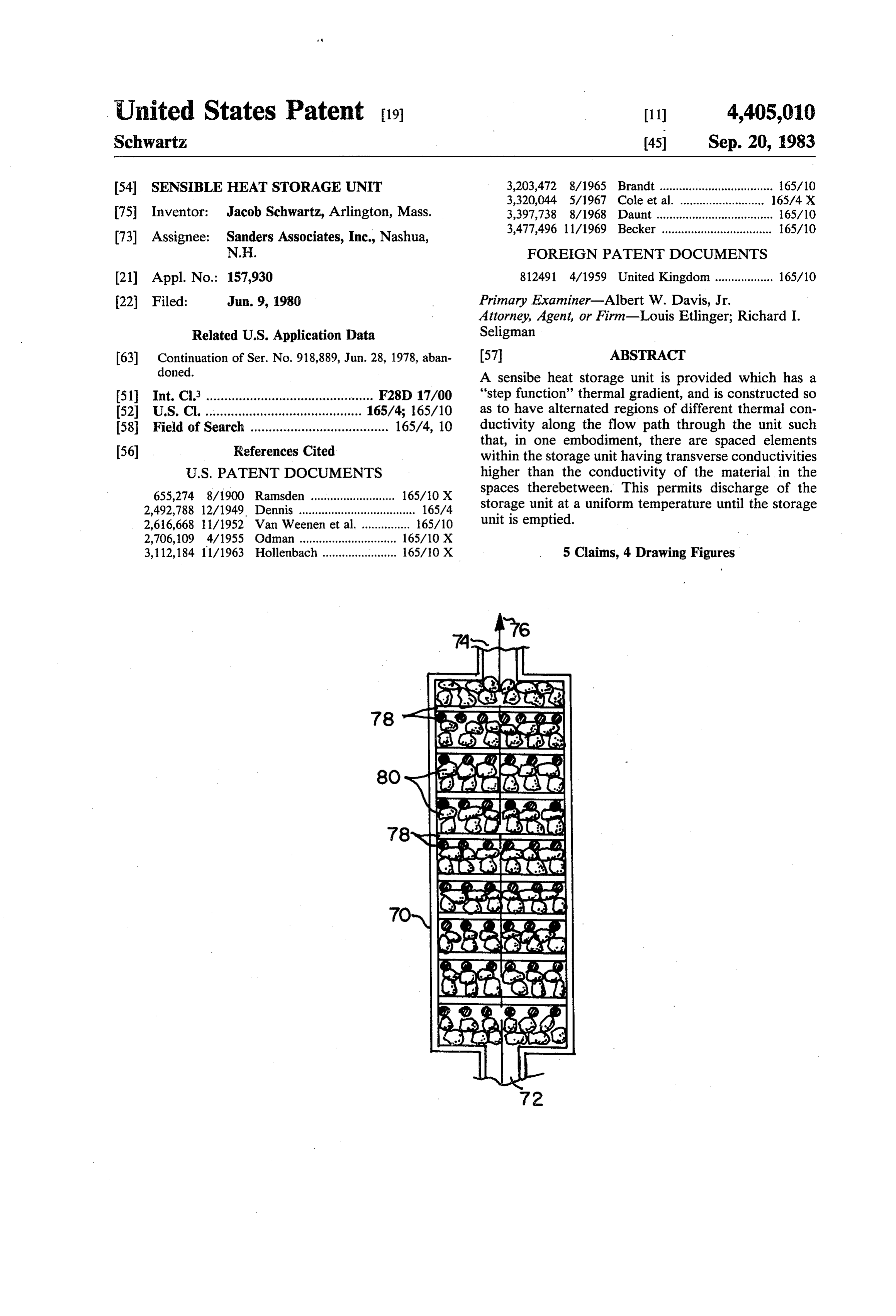
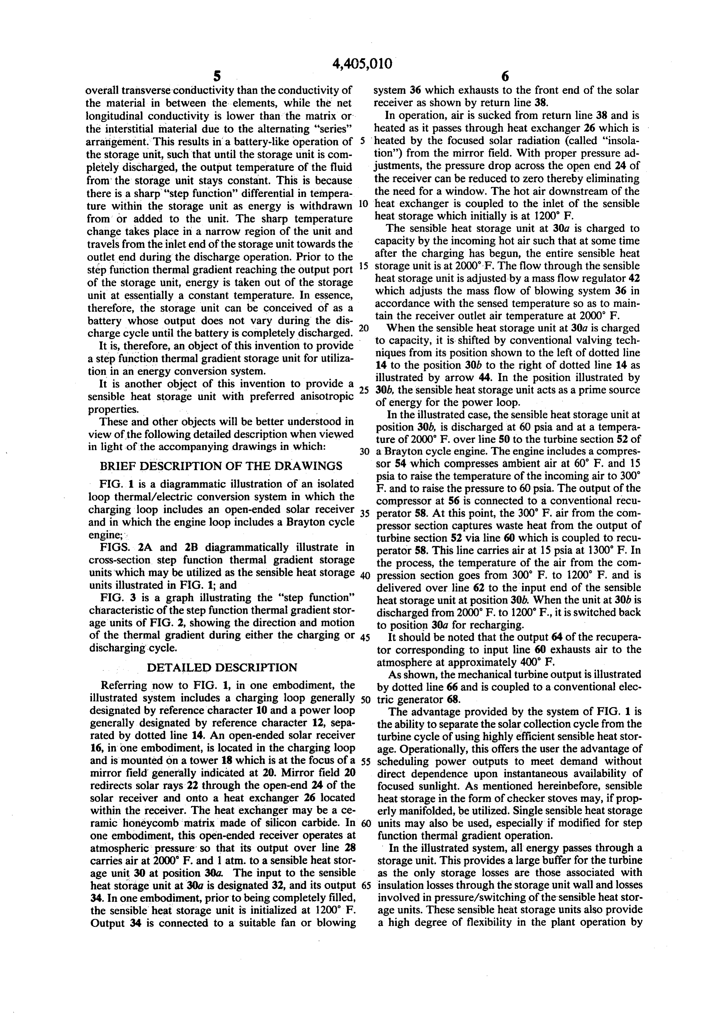
Referring to FIGS. 2A and 2B, there are shown two charged and discharged in any direction. As such, they are said to be "bi-directional.'
different types of sensible heat storage units in which a Alternatively, the thickness and thermal conductivity step function thermal gradient can be achieved. of the materials utilized within the unit may be given With respect to FIG. 2A, the unit may have a housing asymmetric properties such that they are no longer 70 having an inlet 72 and an outlet 74 in which the flow 25 bi-directional. In this case, it might be useful to make the direction and path is indicated by dotted arrow 76. This transition portions at the outlet end of greater thicke unit is packed with spaced apart isotropic structures 78 ness than those at the inlet end. which may be rods or matrices of metal or materials Although preferred embodiments of the invention such as mullite or cordierite. It will be appreciated that have been described in considerable detail for illustra these structures are spaced apart along a flow path 30 tive purposes, many modifications will occur to those indicated by arrow 76. In between these structures are regions 80 which may be filled with material having a skilled in the art. It is, therefore, desired that the protec lower thermal conductivity in the flow direction, such tion afforded by Letters Patent be limited only by the as clay refractories which have a conductivity of 0.1 trueI claim:
scope of the appended claims.
BTU/Hr./sq. ft. 35
As shown in FIG. 2B, unit 70, may carry segments 82 1. A step function thermal gradient sensible heat stor which may be honeycomb discs or perforated blocks of age unit comprising:
mullite or cordierite to provide for the higher thermal a housing having an inlet and an outlet and a flow conductivity in the transverse direction than the spaces path therethrough from said inlet to said outlet; therebetween. The low thermal conductivity areas 84 40 a first plurality of structures permitting fluid flow are merely provided by spaces occupied by air or other therethrough disposed within said housing, said gases passing through the unit. A property of the above structures being spaced apart along substantially mentioned materials is also that they retain heat. Thus, the entire length of said flow path; alternatively, what is provided are spaced segments of a second plurality of structures permitting fluid flow high heat retaining material. 45 therethrough disposed within said housing in be Alternatively, any higher thermal conductivity seg tween said first plurality of structures, said second ment transverse to the flow path may be utilized, such plurality of structures providing the principal heat as corrugated materials interspaced with flat materials storage medium for the unit; of the same. material structure (not shown). Transverse said first plurality of structures providing a substan metal plates may be used now and then to get maximum 50 tially straight-line shunt between the sides of said net anisotropy if needed. housing and thereby yielding a substantially higher The important aspect of the unit is that in order to net thermal conduction transverse to said flow path achieve the step function thermal gradient, there are throughout substantially the entire housing than regions spaced apart and transverse to the flow path the thermal conductivity of said second plurality of which have higher thermal conductivity than that of 55 structures such that a step function thermal gradi- '' the spaces in between these regions. ent is provided which permits discharge of the Referring to FIG. 3, a graph is shown of the step storage unit at a substantially constant output tem function thermal gradient. This step function thermal perature.
gradient is shown by solid line 90 for the charging or 2. The unit of claim 1 wherein said first plurality of discharging case. During charging, the step function 60 structures comprise a metal.
thermal gradient moves from the left to the right, from 3. The unit of claim 1 wherein said second plurality of the inlet end of the thermal storage unit to the outlet end structures comprise refractories. as indicated by arrow 94. During discharge, the step 4. The unit of claim 1, further including a medium function moves in the reverse direction as indicated by interspersed among said first and second plurality of arrow 95. The transition region which carries the step 65 structures having a thermal conductivity lower than function thermal gradient has a length in the flow direc that of said first and second plurality of structures. tion indicated by x. As indicated hereinbefore, a step 5. The unit of claim 4 wherein said medium is air.
function thermal gradient is, in essence, defined by the
Provenance
- Collection
- Cited prior art
- Original PDF
- patentimages.storage.googleapis.com →
- Filed
- 1980-06-09
- Pages
- 8
- Method
- pdftotext (the PDF's own text layer) + pdftoppm 300dpi page scans
- Source
- Google Patents bibliographic record
- Granted
- 1983-09-20
- Inventors
- Jacob Schwartz; Sanders Associates Inc
- Transcribed from
- patentimages.storage.googleapis.com →