patent · US4003660
Sensing head assembly for multi-color printing press on-line densitometer
18 January 1977
Page 1 — bibliographic record
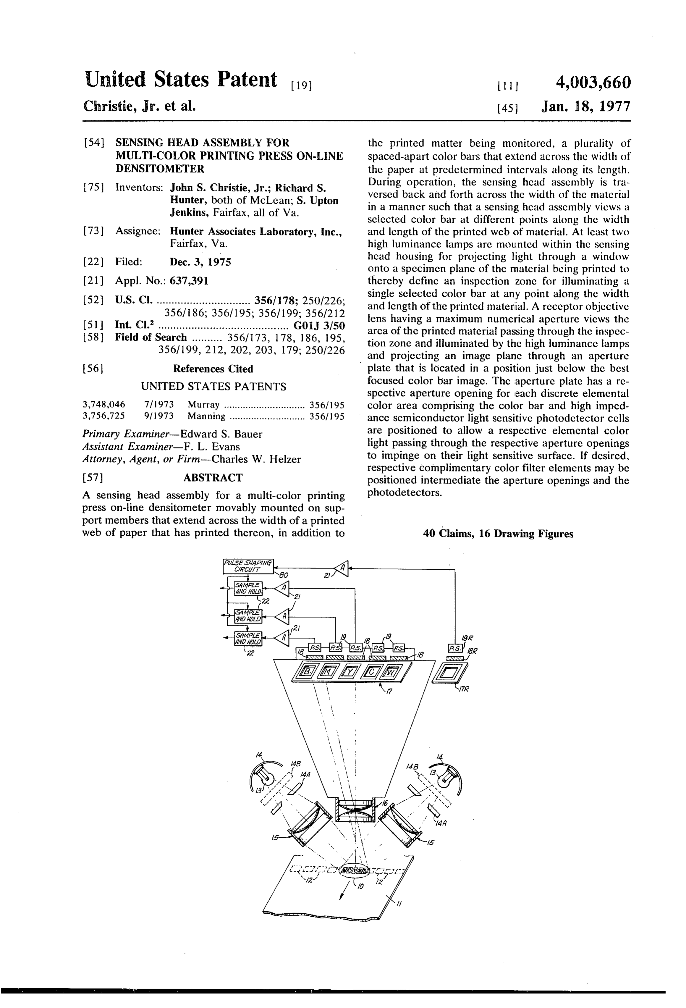
United States Patent to ll 4,003,660 Christie, Jr. et al. (45 Jan. 18, 1977 54). SENSING HEAD ASSEMBLY FOR the printed matter being monitored, a plurality of MULTI-COLOR PRENTNG PRESS ON-LINE spaced-apart color bars that extend across the width of EDENSTOMETER the paper at predetermined intervals along its length. 75 Inventors: John S. Christie, Jr.; Richard S. During opcration, the sensing head assembly is tra Hunter, both of McLean; S. Upton versed back and forth across the width of the material Jenkins, Fairfax, all of Va. in a manner such that a sensing head assembly views a sclected color bar at different points along the width 73 Assignee: Hunter Associates Laboratory, Inc., and length of the printcd wcb of matcrial. At least two Fairfax, Va. high luminance lamps are mountcd within the sensing 22 Filed: Dec. 3, 1975 hcad housing for projecting light through a window onto a specimen plane of the material being printed to (21) Appl. No.: 637,391 thereby define an inspection zone for illuminating a 52 U.S. Cl. ............................... 356/178; 250/226; single selected color bar at any point along the width
and length of the printed material. A receptor objective (51 Int. Cl.'........................................... G01 3/50 lens having a maximum numerical aperture views the 58) Field of Search .......... 356/173, 178, 186, 195, area of the printed matcrial passing through the inspec 356/199, 212, 202, 203, 179; 250/226 tion zone and illuminated by the high luminance lamps and projecting an image planc through an aperture 56 References Cited plate that is located in a position just below the best UNITED STATES PATENTS focused color bar image. The aperture plate has a re spective aperture opening for each discrete elemental 3,748,046 7/1973 Murray .............................. 356/195 color area comprising the color bar and high imped 3,756,725 9/1973 Manning ............................ 356/195 ance semiconductor light sensitive photodetector cells Primary Examiner-Edward S. Bauer are positioned to allow a respective elemental color Assistant Examiner-F. L. Evans light passing through the respective aperture openings Attorney, Agent, or Firm-Charles W. Helzer to impinge on their light sensitive surface. If desired, respective complimentary color filter elements may be 57 ABSTRACT positioned intermediate the aperture openings and the A sensing head assembly for a multi-color printing photodetectors.
press on-line densitometer movably mounted on sup port members that extend across the width of a printed web of paper that has printed thereon, in addition to 40 Claims, 16 Drawing Figures
RNRNNRNS WNSR
Page 2
Drawing sheet — no readable text.
Page 3
Drawing sheet — no readable text.
Page 4
Drawing sheet — no readable text.
Page 5
Drawing sheet — no readable text.
Page 6
Drawing sheet — no readable text.
Page 7
Drawing sheet — no readable text.
Page 8
Drawing sheet — no readable text.
Page 9
which allows better maintenance of color both along
SENSING HEAD ASSEMBLY FOR MULTI-COLOR and across the length of a web of multi-colored printed PRINTING PRESS ON-LINE DENSITOMETER material.
BACKGROUND OF INVENTION
Still another object of the invention is to provide an improved sensing head assembly wherein the signals 1. Field of Invention derived from the passing of the individual color areas of This invention relates to a new and improved sensing a color bar through the inspection area of the assembly head assembly for use as an on-line densitometer on can be used for control of registeration during a multi multi-color printing presses. color printing operation.
More particularly, the invention relates to a sensing 10 In practicing the invention, an improved sensing head heat assembly which senses and derives output electric assembly is provided for a multi-color printing press signals representative of the small spot reflectance of on-line densitometer. The assembly is comprised by a the ink colors (hence, density of the ink) used in a sensing head housing movably mounted on support multi-color printing press. The assembly is designed for members that extend across the width of a web of mate use on-line during normal printing operations of the 5 rial being printed by a multi-color printing press. multi-color press to provide continuous monitoring of Means are provided for traversing the sensing head the printing ink density. The output signals derived housing back and forth across the width of the web of from the assembly can be employed to provide a visual printed material with the material having printed read out to a press man who then can appropriately thereon a plurality of spaced-apart color bars extending adjust the ink characteristics as it is applied to maintain 20 across the width of the material at predetermined inter some preset standard. Alternatively, the output signals vals along its length. The color bars comprise a plural can be applied directly to control ink application by an ity of aligned discrete areas each printed with an ele automatically controlled printing press. mental color such that each color bar includes all of the 2. Prior Art Problem elemental colors appearing on the printed material. A U.S. Pat. No. 3,756,725 - issued Sept. 4, 1973 dis 25 multiplicity of high luminance lamps are mounted closes an apparatus and method for determining the within the sensing head housing adjacent respective density of color reproduction in a multi-color printing reflectors for projecting light through window means in press while on-line during printing operations. The the under side of the housing and onto a common con on-line densitometer disclosed in U.S. Pat. No. vergence point located below the specimen plane of the 3,756,725 employs a pulsed, elongated flash lamp light 30 material being printed to thereby define an inspection source which illuminates a multiplicity of test patches zone for illuminating selected color bars at any point and adjacent reference surfaces simultaneously, and along the width and length of the printed material. A the pulsed light source must be gated-on in synchro receptor objective lens means is provided having a nism with the movement of the color test patches and maximum numerical aperture for viewing an area on adjacent reference surfaces past an inspection zone. 35 the printed material passing through the inspection Such an arrangement possesses built-in complexity that Zone and for projecting an image of a selected color bar necessitates the inclusion of complex and expensive onto an image plane located within the sensing head synchronization circuitry for the pulsed flash lamp light housing. An aperture plate is located at a position source. To maintain this synchronizing circuitry in below the best focused color bar image and has respec proper working order requires highly paid, skilled tech 40 tive aperture openings corresponding in position to nicians and requires a relatively high initial cost for each discrete elemental color area comprising the color manufacture and installation of the system. In addition, bar. Opto-electric conversion means comprising small the use of the pulsed flash lamp light source to derive area, high impedance semiconductor light sensitive the color density output signals, introduces undesired photodetector cells are positioned in back of respective transients in the normal operation of the instrument 45 aperture openings in the aperture plate and are respon which complicate its calibration and proper alignment. sive primarily only to a respective elemental color light Further, the use of an elongated light source for illumi corresponding to the discrete elemental color area of nating a multiplicity of color bars extending across the the color bar being imaged through the respective aper width of the material being monitored, can introduce ture openings.
non-uniformities in illumination of the color bars as 50 In a preferred embodiment of the invention photo they are read out. To make available an improved on metric standardizing means are provided for viewing by line densitometer sensing head assembly which does the receptor objective lens means during each traversal not possess these undesirable characteristics, the pre of the sensing head housing across the width of the sent invention was devised. printed material for providing a background data refer 55 ence reflectance level. The photometric scale standard
SUMMARY OF INVENTION izing means comprise blocks having white and dark It is therefore a primary object of the present inven grey standard surfaces positioned at either end of the tion to provide a new and improved sensing head as cross support members. The blocks are located under sembly for a multi-color printing press on-line densi spring returned slide covers that are engaged and tometer. 60 opened by the movable sensing head housing at the end Another object of the invention is to provide such a of each traverse thereof across the width of the mate sensing head assembly which is relatively simple in rial being inspected to allow viewing of the blocks by design, construction, installation, and maintenance in the semiconductor. light sensitive photodetector cells. comparison to known prior art densitometers, operates The semiconductor light sensitive photodetector continuously, and provides fast response to facilitate 65 cells are responsive to light rays within the entire visible quick adjustment to acceptable color printing. spectrum and employ a respective filter member posi A still further object of the invention is to provide an tioned in front of the cell designed to filter out all but improved on-line densitometer sensing head assembly a respective elemental color light or its complement.
Page 10
To facilitate use of the assembly with different multi the aperture. The sharply differentiated leading edge color printing press operations, the respective light signal pulses may then bc supplied to a registration filter members may be secured together in a removable control for the multicolor press as an aid in maintaining aperture plate tray for ready removal and replacement proper registration.
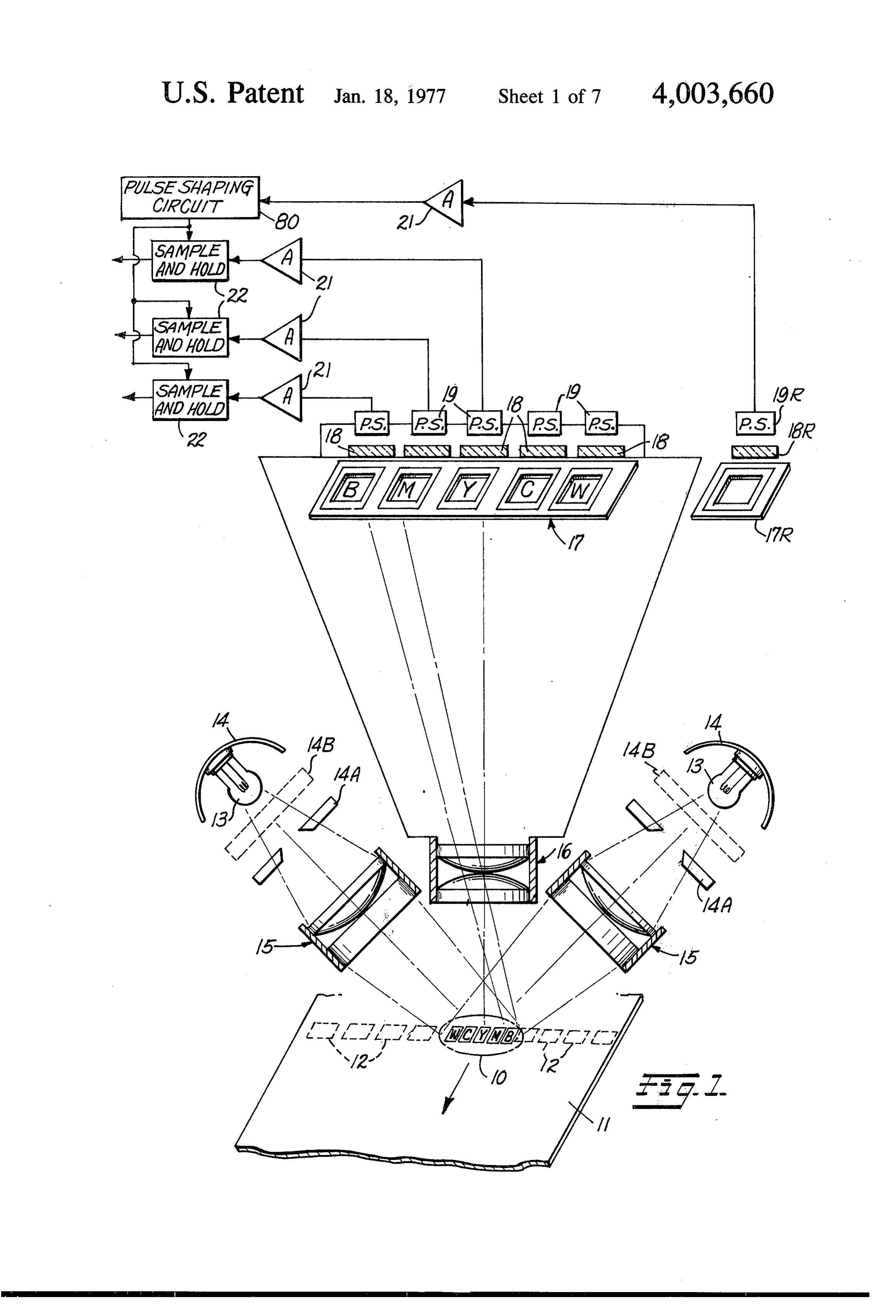
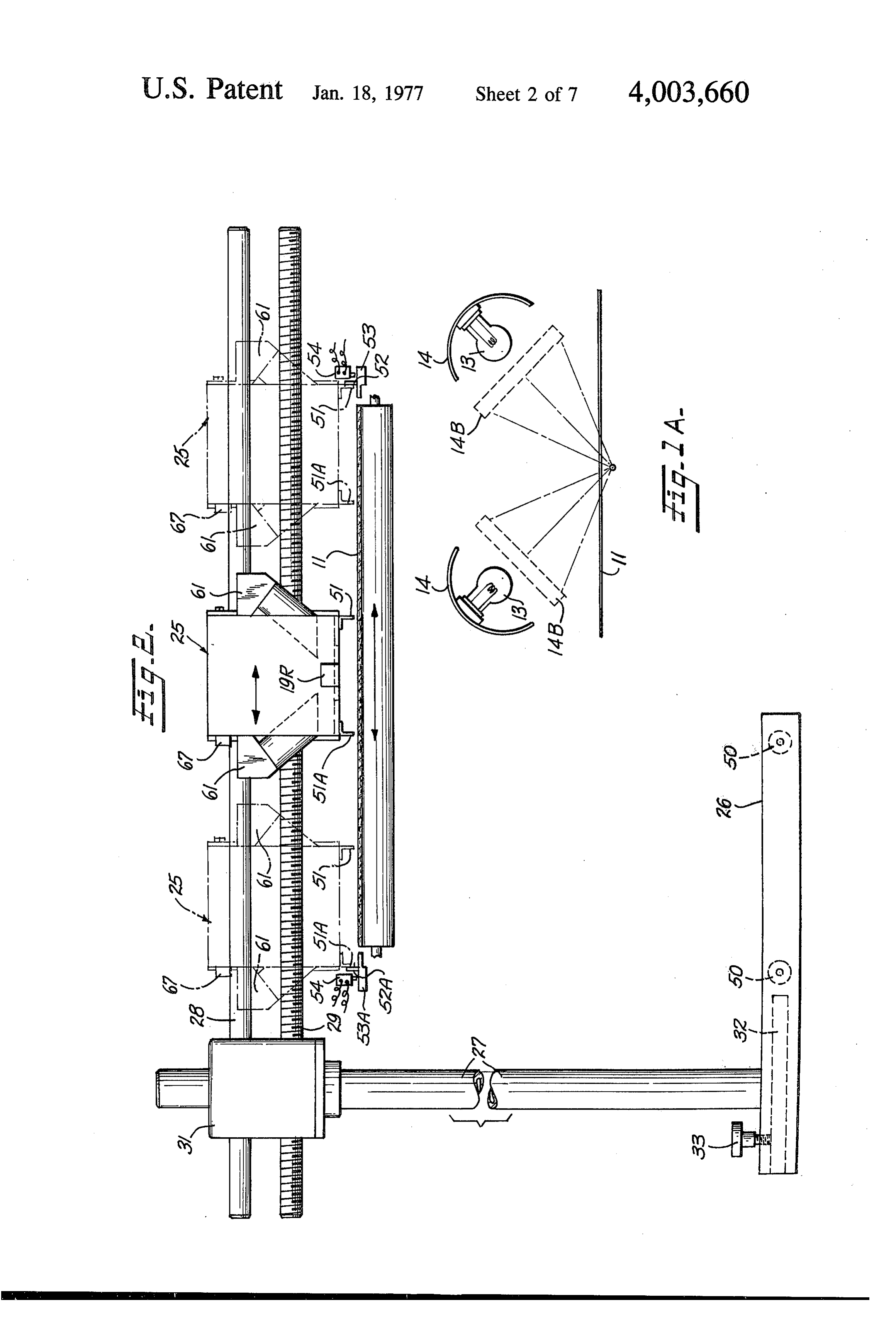
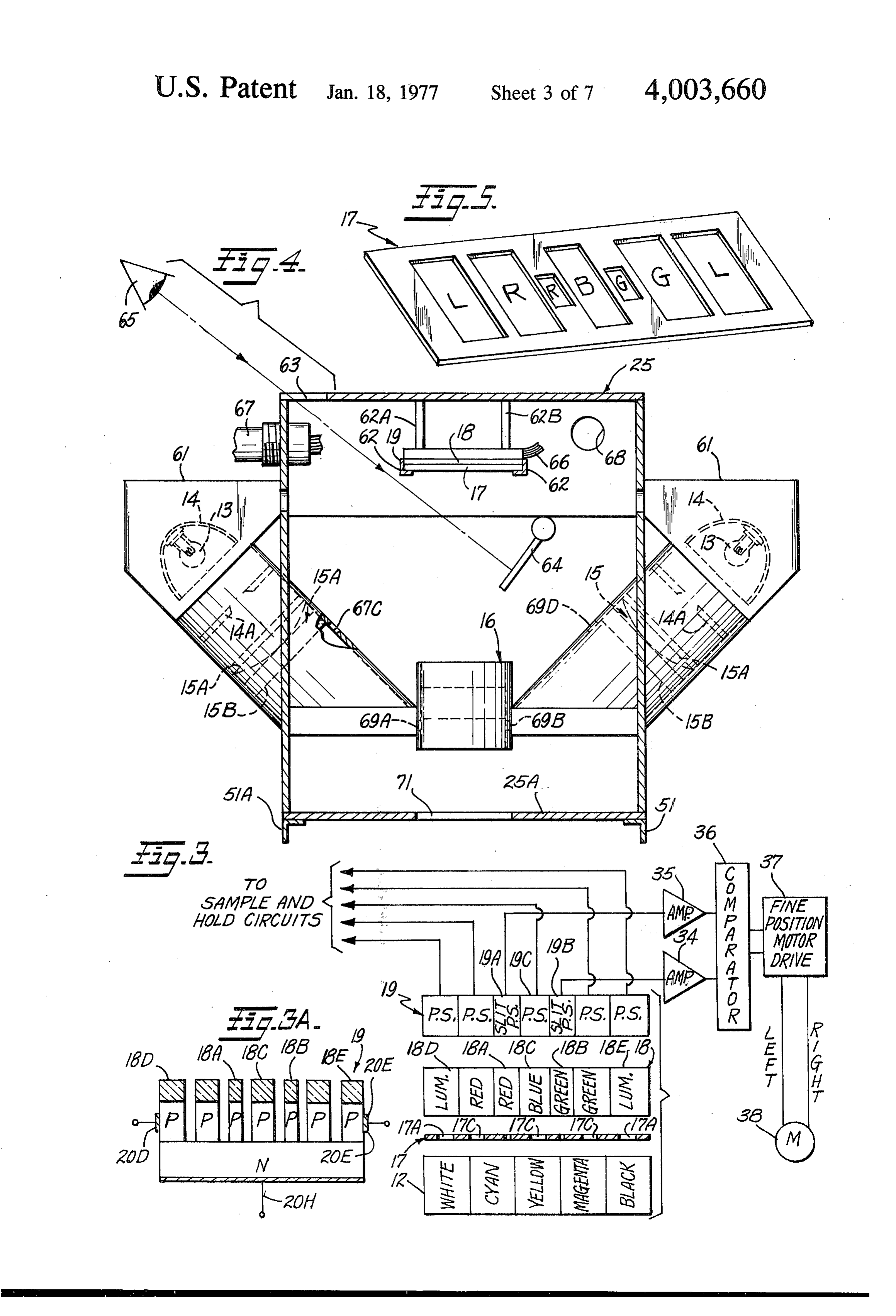
with light filter members having different color re 5 sponse characteristics. BRIEF DESCRIPTION OF THE DRAWINGS The receptor objective lens means preferably is ad These and other objects, features, and many of the justable to allow optimum imaging of a color bar pass attendant advantages of this invention will be appreci ing through the inspection zone onto the aperture ated more readily as the same becomes better under plate. To facilitate alignment and focusing of the as- 10 stood by reference to the following detailed descrip sembly, the sensing head housing further includes a tion, when considered in connection with the accompa mirror and suitably aligned viewing window positioned nying drawings, wherein like parts in each of the sev to allow an operator of the assembly to view the image cral figures are identified by the same reference char of a color bar as it is projected onto the aperture plate. acter; and wherein:
Sample and hold circuit means are mounted within 5 FIG. 1 is a schematic, functional block diagram of a the sensing head housing and are responsive to the new and improved sensing head assembly constructed output electric signals from the respective semiconduc in accordance with the invention and showing it in tor light sensitive cells for deriving respective output conjunction with a moving web of multi-color printed clectric signals representative of the small spot reflec material for use as an on-line densitometer for multi tance and therefore the reciprocal of the printing den- 20 color printing presses;
sity of the colored ink cmployed in printing each dis FIG. 1A is a partial schematic view of the illuminat crete elemental area of the color bars. Gating means ing light sources and their associated reflectors and are provided for sensing the presence of a color bar in illustrates the manner in which light from the sources is the inspection zone and gating-on the sample and hold focussed relative to a moving web of paper being moni circuit means at a precise point in the movement of a 25 color bar through the inspection zone. The gating tored. FIG. 2 is a schematic front view of the sensing head means may comprise a separate photodetector for sens assembly comprising the invention showing it in rela ing a separately printed index mark on the printed tion to a web of multi-color printed material with the material and developing a suitable gating-on signal sensing head housing thereof illustrated in different pulse. Alternatively, the gating means may comprise a 30 traverse positions extending across the width of the pulse shaping circuit coupled to the output from at web of multi-color printed material being monitored; least one of the semiconductor light sensitive cells for FIG. 3 is a schematic functional diagram illustrating suitably shaping the output signal pulse produced upon an exemplary arrangement for a color bar pattern and a color bar passing through the inspection zone and its relation to the design of the aperture plate, filters, providing a properly shaped and timed gating signal 35 pulse coincidental with the movement of the longitudi and ing photodetectors employed in the sensing head hous together with certain control and calibration cir nal center of the color bar into the inspection zone.
In order to precisely control the traverse positioning prising part of thetheinvention;
cuitry used with sensing head assembly and com of the sensing head housing, separate small area light responsive semiconductor cells are positioned on each 40 FIG.3A is a sectional view of an alternative construc side of a selected traverse positioning guide point with tion for the photodetector array constructed in accor the additional, separate, small area light responsive dance with microminiature circuit fabrication tech niques and which eliminates the need for separate aper semiconductor cells being highly responsive to elemen ture and filter plates;
tal colors that are employed to define the selected
FIG.
traverse positioning guide point. Feedback circuit 45 mechanical 4 is a partial sectional view showing certain means are responsive to the output from the additional, housing; details of construction of the sensing head separate small area semiconductor cells for deriving FIG. 5 is a perspective view of a removable aperture feedback positioning signals for supply to the drive means for traversing the sensing head housing back and plate and filter assembly employed in the sensing head forth across the cross support member whereby precise 50 housing shown in FIG. 2;
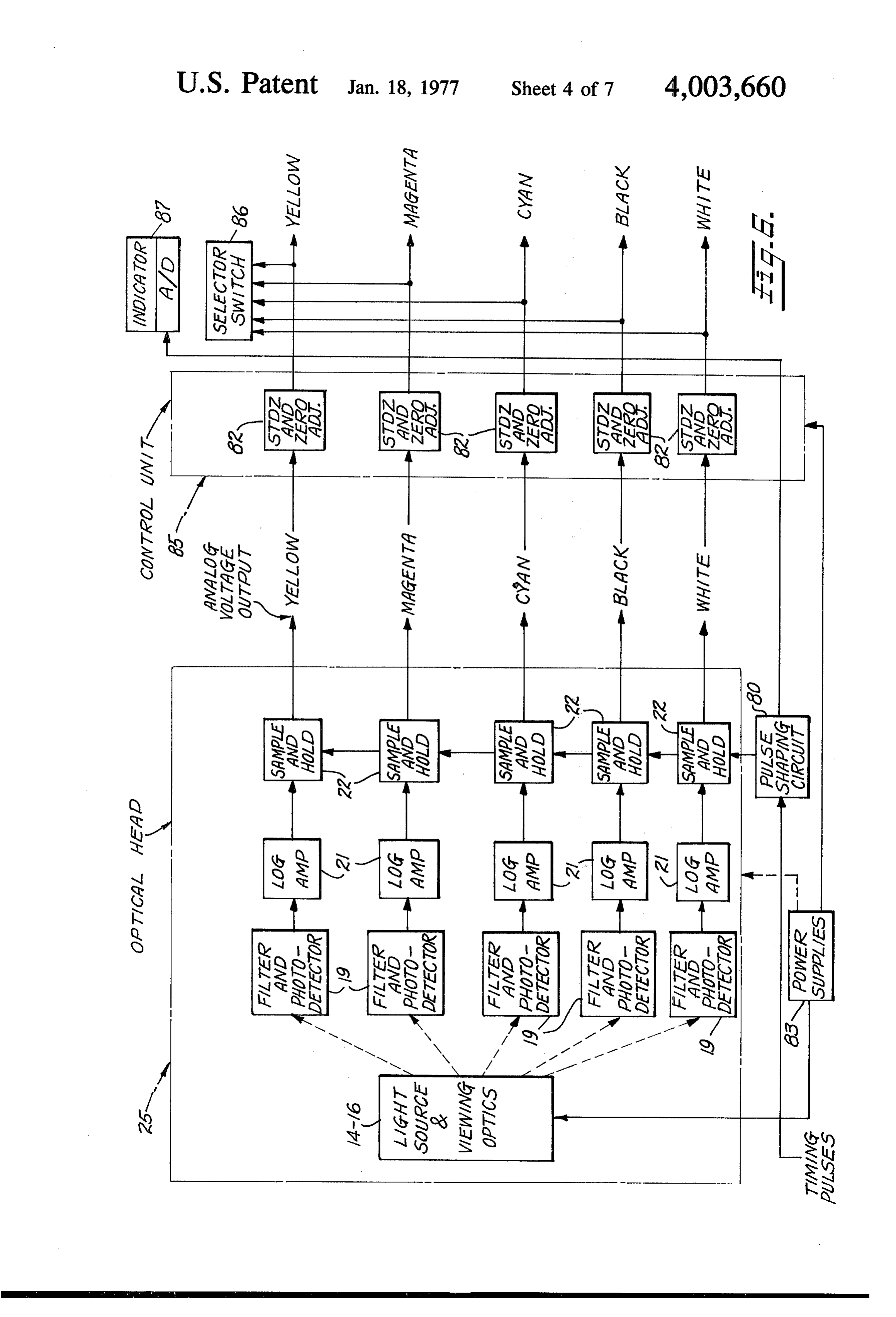
positioning of the sensing head housing across the FIG. 6 is a functional block diagram of the signal width of the printed material at the same point over processing assembly;
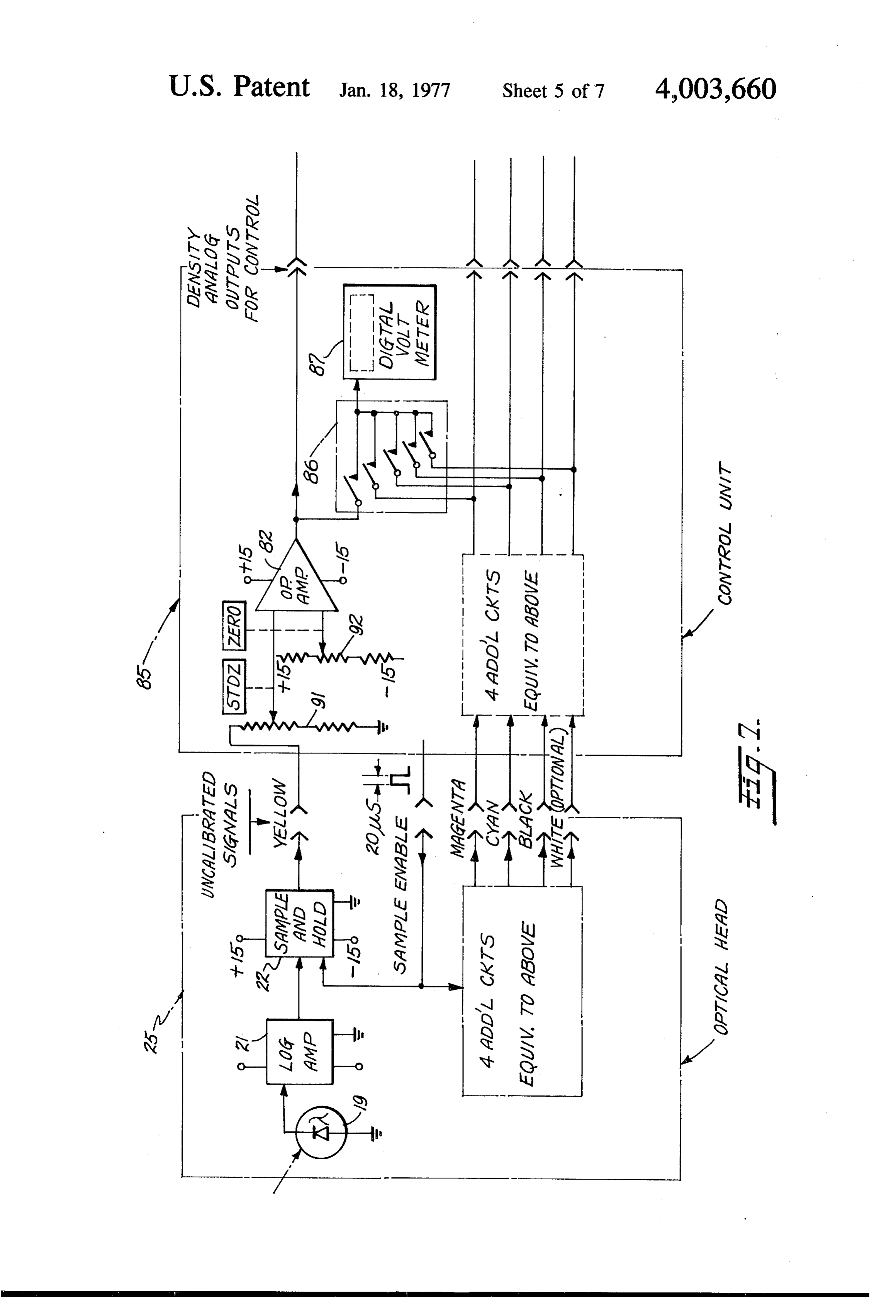
circuitry employed with the sensing head each repeated color block pattern, can be achieved.
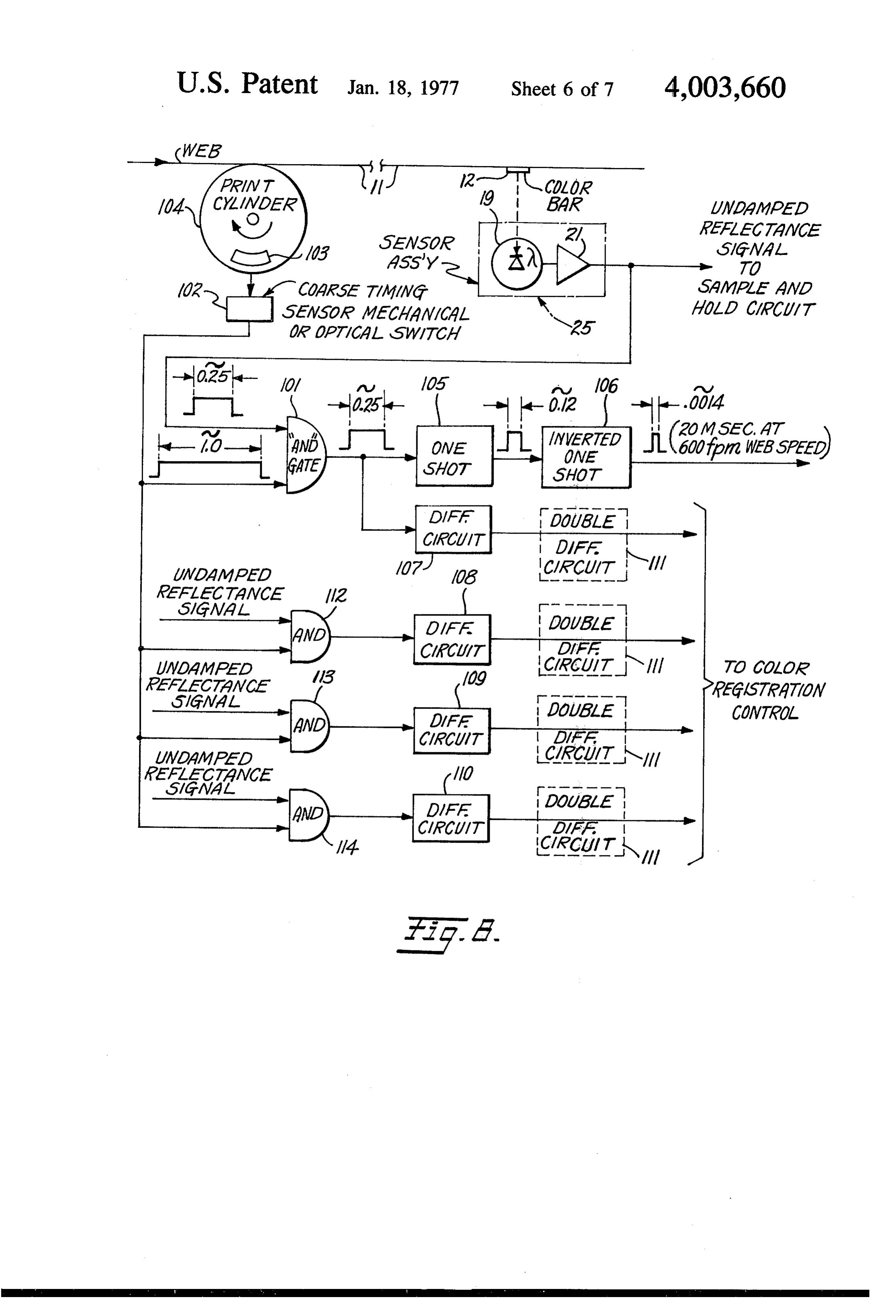
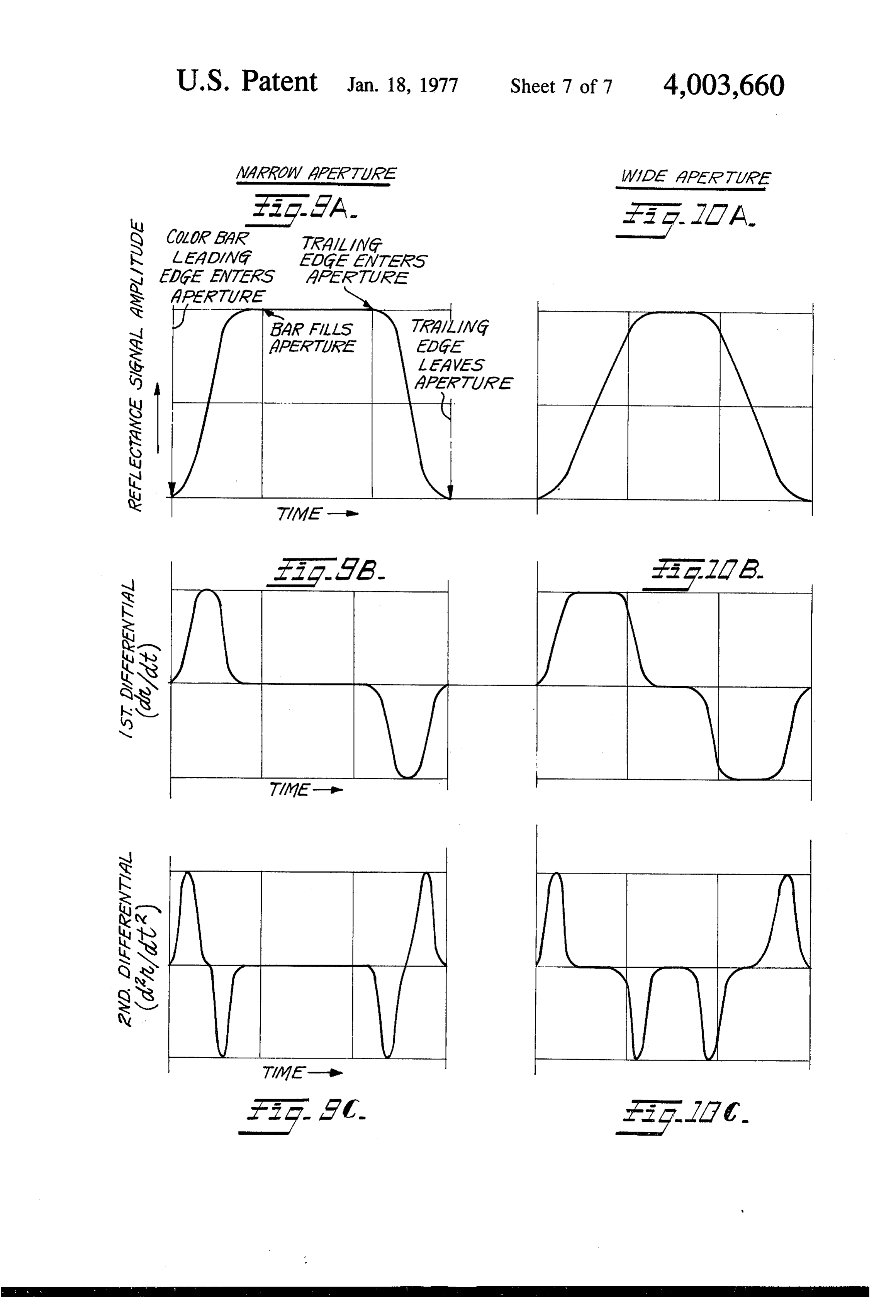
A further advantageous feature made possible by the FIG. 7 is a more detailed circuit block diagram of the invention is the ability to develop suitable control sig- 55 construction of one of the color signal processing chan mals for controlling registration of the various elemen nels comprising a part of the system shown in FIG. 6; tal color areas comprising each color bar. This is FIG. 8 is a schematic block diagram of an alternative achieved by differentiating the output signals from the arrangement for deriving a gating enabling signal for several photodetectors in cases where a narrow slit use with the circuitry of FIGS. 6 and 7, and also for aperture is employed and the rise time of the signal 60 deriving suitable color registration control signals; pulses produced by the photodetectors is controlled by FIGS. 9A through 9C illustrate typical wave forms of the width of the aperture. Where wide apertures are the reflectance signal and the first and second deriva employed in the sensing head, double differentiation of tives thereof derived with a rectangular aperture open the photodetector output signals may be required in ing (small spot reflectance) employed in the sensing order to provide signal pulses with short rise time which 65 head assembly; and are dependent only on the sharpness of the leading FIGS. 10A through 10C illustrate typical wave forms edge of the elemental color areas comprising the color of the reflectance signal and the first and second deriv bars and the aperture opening rather than the width of atives thereof derived with the use of a wide aperture
Page 11
rectangular opening (large spot reflectance) employed Alternately, the light may be focused directly on the in the sensing head assembly. color bar pattern by means of the elliptical reflectors as DETALED DESCRIPTION OF PREFERRED shown in FIG. A. Preferably the reflectors 14 are EMBODIMENT dichroic reflectors for minimizing infra-red compo 5. nents from light imaged on the inspection area 10. If
FIG. 1 is a schematic, functional block diagram of a new and improved sensing head assembly constructed dichroic filters reflectors are not employed, then infra-red shown in dotted outline form at 14B may be in accordance with the invention for use as an on-line employed.
densitometer for multi-color printing presses. The sens Light reflected from each of the elemental color ing head assembly comprises a small spot reflectometer 10 areas comprising a color bar passing through the in that is used to measure the reflectance, and therefore spection zone 10 is imaged upon a receptor-objective the printing density of the ink colors used in a multi lens assembly 16. The receptor-objective lens assembly color printing operation. The device is used to monitor 16 comprises wide aperture, flat field lens assembly for the reflectances of a multi-colored printed material collecting and focusing while the press is in operation, and for this purpose is 15 elemental color areas in light the received from each of the color bar and projecting an designed to be mounted on the press over the moving image of the color bar upon an aperture plate assembly web of multi-color printed material shown at 11. The 17. The aperture plate 17 serves to isolate a particular sensing head assembly can be used with both sheet and area of each of the elemental colors comprising the web presses, and is relatively unaffected by the method color bar and passes the respective elemental color of ink application (i.e.; off-set or letter press). It is 20 image through a complimentary filter shown at 18 to preferred to provide a narrow strip of color bars 12 which extend completely across the sheet or web of cause a it to impinge upon the photosensitive surface of respective photosensitive device 19. The photosensi printed material 11 and are printed on the web material by the press cylinders. It is anticipated that there will be tive device 19 preferably comprises a semiconductor photo diode or other high impedance, fast responding a color bar for each ink control key provided on the 25 photodetector. The photosensors 19 develop respec multi-color printing press. The color bars comprise a plurality of aligned, discrete areas each printed with an tive electric output signals which are representative of elemental color so that each color bar includes all of the reflectance and hence density of each of the ele the elemental colors being printed on the material and, output mental colors comprising the color bar. The electric if desired, may also include an ink-free area for sensing 30 signals are then supplied through suitable ampli the substrate reflectance (white). A typical color bar fying circuits 21 preferably to sample and hold circuits pattern may be comprised of blocks, either rectangular 22 for display and use by an operator of the multi-color or square, which are of the order of one-eighth of an printing press for making appropriate adjustments to inch to one-quarter of an inch in length and width. A the ink control keys to maintain predetermined color four color printing operation would have white (the 35 density standards. If desired, this can be done automati paper itself), cyan, yellow, magenta, and black squares cally if an automatically controlled multi-color printing placed side by side to form the color bar. The color press operation is being monitored.
bars 12 are printed side by side in a line across the FIG. 2 of the drawings illustrates in greater detail the width of the sheet of printed material and the line of manner in which the sensing head assembly is mounted color bars is repeated many times at periodic intervals 40 with respect to the moving web or sheet of multi-color along the length of the web. printed material shown at 11. The sensing head assem In FIG. 1, a typical color bar pattern 12 has been bly is contained within a sensing head housing 25 that exploded to show it in detail in the center of the web of is supported by a base stand 26 and vertical column 27 printed material. The sensing head assembly is posi for rotatably supporting a cantilevered guide arm 28 tioned over the web of printed material to view the 45 and reversible rotating drive screw 29 or other similar color bars and is comprised by a multiplicity of high linear drive for causing the sensing head housing 25 to luminance lamps indicated at 13 which may be posi scan back and forth across the width of the web of tioned within suitable elliptical reflectors shown at 14 printed material 11 in the manner indicated by the for projecting a highly intense beam of light at an angle dotted outline forms. The cantilevered guide arm 28 of incidence of substantially 45 with respect to the 50 and reversible, rotating screw drive 29 are conven plane of the multi-color printed material 11. While two tional in construction and are secured to and extend high luminance lamps have been illustrated in FIG. 1, it from a motor housing 31 having contained therein a is believed obvious that three, four, or more lamps reversible electric motor for driving the reversible, could be employed and appropriately arranged to screw drive 29 to cause the sensing head housing 25 to project an elliptically shaped spot of light onto a central 55 be moved either right or left depending upon the direc area or zone 10 which is defined as the inspection zone tion of rotation of the rotating screw drive. The motor for illuminating only a selected color bar along the housing 31, cantilevered guide arm 28 and rotating width of the web of printed material as the color bar screw drive 29 are secured to the vertical column 27 passes through the inspection zone 10. For this purpose and the entire assembly may be mounted in a swivel or light from each of the high luminance lamps 13 may be 60 thrust bearing circular plate 32 rotatably seated in base projected through a respective aperture 1A and a 26 and held in place by a set screw 33. By this means modified condensor lens assembly 15 whose construc the assembly can be rotatably adjusted to facilitate tion will be described more fully hereafter in connec proper alignment of the guide arm 28 and screw drive tion with FIG. 4 of the drawings. The condensor lens 29 over the web or printed material 11. Retractable assemblies 15 focus the light to form a rectangular or 65 wheels shown at 50 are provided on base member 26 to elliptically-shaped spot of light that defines the inspec allow the assembly to move in or out relative to the web tion zone 10 for encompassing only a single color bar of printed material on the support rolls or to allow 12 on the surface of the web of printed material 11. access for servicing the printing press.
Page 12
In operation, the reversible motor 31 for rotating within the visible spectrum. In addition to the semicon screw drive 29 that causes the sensing head housing 25 ductor photodetector cells associated with each of the to be positioned at some desired traverse position filter elements for the elemental color areas comprising across the width of the web of multi-color printed ma the color bar 12, additional slit-like photosensitive cells terial 11, may be operated open loop from a control 19A and 19B are provided on each side of the central computer that is programed to position the sensing photosensitive cell 19C and are designed to respond head housing at predetermined points across the width respectively to light from the cyan and magenta ele of multi-colored printed material in accordance with mental color areas of color bar 12 that are on cach side known statistical sampling procedure whereby authen of the yellow elemental color area which is centrally tic sampling of the density of the clemental color areas 10 disposed in each color bar. The electrical outputs from comprising the color bars is achieved in order to effec the separate additional slit photodetector cells 19A and tively monitor the multi-color printing operation. The 19B are supplied through respective amplifiers 34 and sensing head housing 25 is traversed at a slow rate and 35 to comparator circuit 36. The comparator circuit 36 at predetermined traverse points determined by the has its output connected to operate the fine servomotor program of the control computer, the sensing head 15 control indicated at 37 which in turn controls the direc drive motor is stopped in order to sense several color tion, rate, and extent of rotation of a servomotor indi bars in sequence. In this manner an average signal cated at 38. Motor 38 is contained within the housing representative of the reflectance of the clemental color 31 and is mechanically coupled to drive the reversible areas at the sampled points, is obtained. rotating gear drive shaft 29 so as to appropriately posi To assure proper width-wise traverse positioning of 20 tion the sensing head housing 25 over the center of a the sensing head housing during read-out, independant desired color bar. Thus, it will be appreciated that in of small variations in the lateral position of the colorthe example shown in FIG. 3, the central yellow color bars, the arrangement shown in FIG. 3 of the drawings area is chosen to define a traverse positioning guide is employed. FIG. 3 depicts the manner in which the point.
sensing head housing 25 is centered over an appropri 25 In operation, the computer or other operator con ate color bar for reading out the density of the respec trolled source of command signals causes the coarse tive elemental color areas comprising the color bar. In servomotor control (not shown) to rotate motor 38 and FIG. 3 an exemplary color bar, shown at 12, is com reversible gear drive shaft 29 in an open loop manner in prised by a white color area, the elemental color areas response to a command from the computer or other of cyan, yellow and magenta, and a black color area. It 30 controlled device, and moves the sensing head housing should be noted that the central yellow elemental color 25 roughly into width-wise traverse position across the area is bordered on one side by cyan and on the other web of multi-colored printed material 1 so as to locate side by magenta. The aperture plate 17 is designed such the sensing head housing substantially over a desired that it has aperture openings 17A which correspond color bar. With the arrangement shown in FIG. 3, substantially in size to the size of the color bars whose 35 should the central yellow color image fall either to one images are projected onto the aperture openings by the side or the other of its proper central position relative receptor-objective lens assembly 16. In addition to the to aperture plate 17, it will produce in the adjoining, normal aperture openings 17A for the elemental colors separate additional slit-shaped photosensor 19A or 19B and white and black, the aperture plate 17 includes a strong imbalanced signal response. This strong signal additional, separate, small slit-like aperture openings 40 response out of either of the separate, additional slit 17B on each side of the centrally disposed aperture shaped positioning photo cells 19A or 19B, is amplified opening 17C associated with the yellow elemental in either of the amplifiers 34 or 35 and supplied to color area of the color bar. comparator 36. Comparator 36 then causes the fine The corresponding complimentary filter elements position servomotor drive 37 to excite reversible motor comprising the filter assembly 18 consist of the compli 45 38 to drive the sensing head housing 25 either right or mentary filter elements red, blue, green, and luminous left so as to balance the signals from separate photode filter elements at each end. The luminous filter ele tector cells 19A and 19B and null the signal from the ments optical characteristics approximate very closely comparator. This results in exactly positioning the sens the response characteristics of the human eye and are ing head housing with the central aperture 17C of aper included in order to obtain a reading indicative of the 50 ture plate 17 and blue filter element 18C of the filter final appearance of the material being monitored. The assembly 18 aligned over the yellow elemental area of red, blue, and green complimentary filter elements the color bar. Thereafter, each of the elemental color correspond respectively to the elemental colors cyan, area responsive photodetector cells comprising the yellow and magenta. In addition to the complimentary photosensor array 19 will respond to the reflected filter elements enumerated above, separate, additional 55 image of the respective elemental color light to which small slit-like red and green filter elements are included they are designed to respond and develop in their out in the filter assembly 18 as shown at 18A and 18B and put respective, elemental color output signals propor are disposed on each side of the centrally located com tional to the reflectance, and hence, density of the plimentary blue filter element 18C which is designed to color ink employed in the printing of the color bars. receive light from the central yellow color elementary 60 FIG. 3A of the drawings shows an alternative con area of the color bar 12. struction for a photosensitive detector array fabricated The respective photosensitive semiconductor cells in accordance with known microminature semiconduc that form the photosensitive assembly 19 may comprise tor integrated circuit fabrication techniques and usable photo diodes, photo triodes or the like but preferably with the fine positioning motor drive control illustrated constitute, small area high impedance silicon semicon 65 in FIG. 3. In FIG. 3A, an array of photosensitive, high ductor photodetector diode cells. Such cells are manu impedance semiconductor PN diode cells are shown at factured and sold by a number of semiconductor manu 19 with each elemental cell being designed to respond facturers and are designed to respond to all light waves to a particular elemental color light or alternatively to
Page 13
9 O white or black light. The light impinges on the light are exposed at the end of each traverse of the sensing sensitive areas of the diodes through selective filter head housing 25 by the respective extensions 52 and layers such as 18A, 18B and 18C deposited over the 52A being engaged by the coacting extensions 51 and light sensitive areas of the respective PN diodes by well 51A. The sensing head housing traversing action then known photoresist masking and etching techniques. 5 slides the spring-return protective cover open at a point Thus the filter layer 18A will pass red light, 18B passes in the traverse while the optical head in housing 25 is green light, 18C passes blue light and 18D and 18E positioned to view the exposed dark grey porcelain comprise luminous filter layers similar to the corre standard or the white porcelain standard. When ex sponding elements of the filter assembly 18 shown in posed in this manner an image of the standard is pro FIG. 3. The respective, different filter layers are depos- 10 jected through all apertures in the aperture plate 17 to ited over respective P-type conductivity layers previ impinge upon all of the respective photodetector cells. ously formed on an underlying N-type conductive sub The electric output signals derived from the photode strate by well known diffusion or epitaxial growth pre tector cells then are supplied through respective ampli cesses. Ohmic contacts are provided to each respective fiers to the computer for use in standardizing the re Player of the PN diode photodetector thus formed as 5 sponse of the system along with electric signals gener shown at 20D and 20E and the common N layer as ated by the closure of a microswitch 54 or 54A that are shown at 20H. The desired reflectance signals supplied engaged by the projections 51 and 51 A simultaneously to the respective sample and hold circuits are obtained with the opening of the standards. By this means the from the respective Player contacts such as 20D and computer or other standardizing arrangement, is in 20E. To simplify the drawings the remaining P layer 20 structed that the standards are being viewed and stan contacts have not been illustrated. Due to the advanced dardizing signals are being supplied. The standard sig technology of semiconductor industry, manufacturers nals thus supplied can then be used by the computer to are now able to produce semiconductor arrays of the develop a standardizing ratio that then is applied in the above-described type which are responsive to any de processing of signals from the respective photodetec sired portion of the visible spectrum with high selectiv 25 tors while the color bars are being viewed for maintain ity. Thus, in the arrangement of FIG. 3A each of the ing calibration of the sensing head assembly. If desired, semiconductor photodetector PN cells comprising the the standardizing output signals obtained in this man total array 19 are designed to respond only to a particu ner could be fed back in a closed loop manner to regu lar elemental color light of a color bar being monitored. late the response of the amplifiers in the output from Proper selectivity in the response of the different ele 30 the photodetector cells in a well known manner and/or mental color responsive photodetector cells is assured to regulate the intensity of the high luminance lamps because the selective filter layers such as 18A, 18B, 13. However, where the sensing head assembly is to be etc. allow only light of a given color to pass through and used in an automatic control with a central computer impinge on the photosensitive surface of the PN photo for maintaining preset ink density standards, the supply detector cell. Consequently, a separate aperture plate 35 of the standardizing signals to the computer for devel is not required. Preferably, the entire array 19 of pho oping a standardizing ratio applied to the photodetec todetector cells including the selective filter layers tor outputs in the above briefly described manner, is 18A, 18B, etc., may be fabricated on a single mono the preferred method of maintaining calibration of the lithic chip in accordance with well known microminia equipment.
ture semiconductor integrated circuit fabrication tech 40 FIG. 4 of the drawings is a sectional view of the con niques and employed as a replaceable element in the struction of the sensing head housing 25 and illustrates sensing head housing 25 in place of the aperture plate some of its structural details. As shown in FIG. 4, the 17, filter array 18, and photodetector array 19. It is high luminance light sources 14 are mounted in exten believed obvious that different arrays would be de sions 61 on either side of the main housing 25. The high signed to respond to different color bar arrangements 45 luminance light sources may comprise quartz hologen in order to accommodate different multi-color printing cycle lamps mounted within elliptical reflectors 14 for operations. Hence, the sensing head assembly readily projecting a high intensity beam of light through aper could be changed and easily adopted by an operator of ture openings 14A and a modified condensor lens as the equipment to accommodate any given multi-color sembly 15 onto an image place so as to result in the printing operation. 50 production of the high intensity, elliptically shaped spot In addition to the above described transverse posi of light indicated at 10 in FIG. 1. This defines the in tioning feature, FIG. 2 illustrates the manner in which spection zone through which the color bars being moni a standardizing signal is obtained with the equipment at tored are caused to pass. In order to reduce the effect the end of each width-wise traverse of the sensing head of distance variations between the specimen, multi housing 25 for use in calibration of multi-color output 55 color printed material being monitored and the optical signals derived from the respective photosensitive port through which the color bars are imaged in the semiconductor cells 19. For this purpose, the sensing sensing head housing, the specimen plane (plane of the head housing 25 has a pair of projections 51 and 51A, multi-colored printed material being monitored) is which extend from each of the lower sides thereof. The located inside the convergence points of the illuminat projections 51 and 51A are designed to engage and 60 ing beam formed by the plurality of high luminance coact with a corresponding set of projections 52 and light sources. While only two high luminance light 52A which extend from the spring-returned cover sources 13 and associated reflectors 14 have been plates of a pair of small housing blocks 53 and 53A, shown, it is believed obvious to one skilled in the art respectively. The housing blocks 53 and 53A are sepa that four or even more light sources could be arrayed rately mounted at each side of the web of printed mate 65 around the optical port in the bottom of the sensing rial and enclose a respective dark grey porcelain stan head housing in order to provide an adequate level of dard and a white porcelain standard. The dark grey and illumination to the inspection zone for a particular white porcelain standards mounted in blocks 53 and 54 monitoring job. Of course parabolic or some reflector
Page 14
configuration other than elliptical can be employed; assembly thus comprised is mounted in a vertically however, it is preferred to use dichroic reflectors for adjustable holder to allow for optimum imaging of the reducing infra-radiation to a minimum. If dichroic re color bar images on the aperture plane of the sensing flectors are not used, then it may be necessary to in head housing in the manner described above. clude infra-red filter elements such as shown at 14B in Due to the presence of the high luminance light FIG. in the light path projected from lamps 13. sources 13 within the sensing head housing 25 it is The image of a color bar passing through the inspec necessary to provide forced circulation of cooling air. tion zone is picked up by a receptor objective lens The cooling air is provided by a cooling fan (not assembly 16 which is designed to provide a maximum shown) mounted on the back of housing 25, and cou numerical aperture in order to deliver sufficient dif pled to the interior of housing 25 through a port 68. fusely reflected light flux to the photodetector cell The interior of the main portion of housing 25 serves as assembly. The image of the respective, clemental color a large plenum for the cooling air and is coupled areas of the color bar is projected through the aperture through ports 68A and 68B to wing portions 61 of the plate 17 and filter clement 18 onto the photosensitive housing 25 in which lamps 13 are mounted. Circulation surfaces of the small area, photodetector cells 19 as 15 of the cooling air is assured by the provision of ports shown in greater detail in FIG. 3. FIG. 5 is a perspective such as shown at 69A, 69B, 69C and 69D to provide a view of a suitable aperture plate 17 for the particular positive flow of cooling air out through the ports and sensing head assembly being described. The aperture across the optical surfaces such as 15B and 16B to plate 17 and associated respective filter elements 18 prevent dust build-up on these surfaces. Suitable baf may be combined in a suitable, readily removable tray 20 fling used in conjunction with the exterior surfaces of shown at 62 to facilitate change over of the cquipment the elements mounted within sensing head housing 25 for use with different multi-color printing monitoring assures necessary circulation of the cooling and cleans operations. The signals produced by the several photo ing airflow within the sensing head for temperature detector cells 19, which are selected for high imped stabilization purposes. While the optical port in the ance to achieve minimum noise gain, are supplied to 25 bottom surface 25A of the sensing head housing 25 has suitable amplifiers and thence to sample and hold pro been illustrated as open to allow the receptor-objective cessing circuitry as will be described hereinafter with assembly 16 to view the inspection zone produced by relation to FIG. 6. the projected illuminating beams of light, for certain As stated earlier, the specimen plane of the multi applications it may be necessary to include a closed color printing material being monitored is located just 30 optical surface or window over the open port 71 to inside the convergence points of the illuminating beams assure cleanliness of the area within the sensing head supplied from the light sources 13 in order to reduce housing. If such an optical window is employed, then a the effect on the output signal of distance variations cleansing flow of air over this surface would be pro between the optical port on the underside of the sens vided.
ing head housing 25 and the specimen being moni 35 FIG. 6 is a functional block diagram of the electrical tored. To further reduce the effect of such distance signal processing system employed with the invention. variations, the aperture plane defined by aperture plate In FIG. 6, the light source and viewing optics contained 17 is located just below the best focused color bar within the sensing head housing 25 are indicated at image by appropriate adjustment of the receptor-objec 14-16. Separate images of the respective elemental tive lens assembly 16. To facilitate alignment of the 40 color areas of the color bar are passed through the optical element to achieve this effect, the sensing head respective filters to impinge upon the photodetectors housing 25 is provided with an additional window 19 that develop at their outputs an electric signal repre shown at 63 and a small adjustable mirror 64 located to sentative of the small spot reflectance of the respective one side of the optical path of the sensing head housing. elemental color areas. The reflectance signals are sup The adjustable mirror 64 is provided with a small han 45 plied to the input of a respective logarithmic amplifier dle (not shown) which can be manipulated by an oper 21 which performs a logarithmic conversion of the ator of the equipment whose eye is indicated at 65. By reflectance signal to provide at their output a signal viewing through the peep hole or window 63 and view representative of the reciprocal of the density of the ing the image of the color bar on the aperture plane 17, respective elemental color areas comprising the color the operator readily can adjust the equipment to pro 50 bars. These color density signals are applied to sample vide the above described beneficial settings for reduc and hold circuits 22 which provide at their output a ing the effect on the output signal of distance variations continuously available analog voltage signal represen between the bottom optical port and the specimen tative of the respective elemental color areas color plane. density such as yellow, magenta, cyan, black and white. The objective lens assembly 5 which may be used in 55 Suitable timing signal pulses obtained from the register conjunction with each of the high luminance light mark detector 19A shown in FIG. 1 are supplied sources to project the elliptically shaped, high intensity through a pulse shaping circuit 80 for supply to each of spot of light defining the inspection zone may be com the respective sample and hold circuits 22 for control prised by a 39 millimeter diameter spherical lens ele ling the timing of sampling the outputs from the respec ment 15A mounted with its convex surface opposing a 60 tive log amps 21. A suitable power supply 83 is pro 54 millimeter diameter cylindrical lens element 15B. vided for supplying electric power to the various elec The modified cylindrical condensing lens assembly thus tric circuits and components in the optical head as well comprised is used in conjunction with each elliptical as the circuit contained in the control unit 85 that may reflector high luminance light source 13 provided on be either a separate unit or comprise an integral part of the sensing head housing. 65 the optical head 25. The control unit 85 includes an The receptor-objective lens assembly 16 may be individual standardizing and zero adjust circuit 82 for comprised by a Schneider flat field enlarging lens hav each of the elemental color signal channels yellow, ing an f/2.8 wide aperture. The receptor-objective lens magenta, etc. In addition, the control unit 85 prefer
Page 15
ably includes a selector switch 86 and an analog/digital the standardizing and zero adjust potentiometers are indicator 87. appropriately set to provide a pre-calibrated output FIG. 7 is a more detailed schematic block diagram from the op-amplifier82. Similar adjustments are made illustrating the construction of one of the elemental to each of the elemental color signal channels in se color signal processing channels, yellow, for example. quence and the operation preferably repeated on a Light from the yellow elemental color area of the color periodic basis and/or each use of the equipment to bar after passing through the aperture plate and the accommodate changes in intensity of the light source blue filter impinges upon the photodetector cell 9 due to aging, etc. If the equipment is changed over to where it produces an electric signal proportional to the provide a signal proportional to reflectance rather than intensity of the yellow light flux. This electrical signal is O color density at the output of the op-amlifier 82 by amplified in a log amp 21 which may, for example, substitution of linear amplifiers for the log amps 21, comprise a commercially available, integrated circuit recalibration of the equipment in the above described logarithmic amplifier such as the Analog Devices 755P manner to accommodate the reflectance signal, also manufactured and sold by Analog Devices, Inc. At this would be required. It is contemplated, that both a log point it should be noted, that if one desires to obtain 15 amp and linear amp could be employed together with output signals from the sensing head assembly which suitable switching circuitry to selectively insert either a are proportional to reflectance rather than to color log amp or a linear amp in the optical head at the op density, the logarithmic conversion performed by the tion of a user. Such an arrangement would be more logarithmic amplifiers 21 would not be required, and expensive than equipment designed to provide only a the amplifier 21 would then comprise a linear type 20 color density output signal or alternatively only a re amplifier such as the Analog Devices 503 integrated flectance output signal; however, for those installations circuit amplifier. where an equipment must serve both purposes, inclu The signal appearing at the output of log amp 21 is sion of the two different amplifier channels may be supplied to one input of a sample and hold circuit 22 justified.
which is also provided with a sample-enabling signal 25 As stated previously with respect to FIG. 1 of the pulse of approximately 20 microsecond duration from drawings, the sample and hold circuits 22 are designed the pulse shaping circuit 80. As explained with respect to average signals over a number of different color bar to FIG. 1 of the drawings, the sample-enabling pulses readings in order to exclude spurious effects. Further are derived from a suitable register mark detector 19R averaging of the color signals also can be accomplished shown in FIG. 1 for providing a suitable timing gating 30 in a control computer. Similarly, standardization of the signal to the sample and hold circuits so that they will color signals can be achieved with a control computer sample the output from the log amps 21 only during by the development of a suitable standardization ratio those intervals while a color bar is passing beneath the utilizing the standardizing signals produced at the end view of the photodetectors 19. The sample and hold of each traverse of the sensing head housing while the circuits 22 may, for example, comprise a commercially 35 white and dark grey standard blocks are exposed. Stan available sample and hold circuit manufactured and dardization in this manner by the control computer sold by the GPS Corporation and identified as SH-1506 would of course complement and add to the effect circuit. achieved with the standardizing and Zero adjust circuits The uncalibrated signal appearing at the output of 82 so as to minimize to the greatest possible extent sample and hold circuit 22 is supplied to a standardiz 40 spurious and transient effects on the output of the ing and Zero adjust circuit comprised by an operational equipment.
amplifier 82 having the input from sample and hold In the design of the equipment, small area, high im circuit 22 supplied thereto over a voltage dividing resis pedance, silicon photodetector cells have been used as tor 91 whose adjustable contact arm is directly con the light responsive devices since such cells have a nected to the direct input of op-amp 82. The inverse 45 more uniform response than other photosensitive de input of op-amp 82 is connected to a potentiometer vices available in the industry, and are more stable in comprised by a potentiometer resistor 92 for providing operation. The technology of silicon photodetector cell a zero adjust correction potential into the inverse input manufacture has been developed extensively in the past terminal of op-amp 82. The op-amp 82 may comprise a several years so that the spectral response of such cells National Semiconductor Corporation LM 308 inte 50 has been extended to cover the complete visible spec grated circuit amplifier of conventional commercial trum. As shown in FIG. 7, the photodetector cells are construction. The compensated output of op-amp 82 used in a short circuit mode, ie., the photodetector cell therefore provides an analog measure of the color den works into an operational amplifier so that the photo sity of the elemental color area viewed by the photode current is a linear function of light and the photo-diode tector diode 19. The remaining elemental color signal 55 capacitance is shunted by the low impedance of the channels not shown in detail in FIG. 7, are identical in operational amplifier input. The advantage of this ar construction and operation to yellow color channel rangement is that the photo-diode capacitance does not described above. affect response time and the overall response of the To facilitate initial alignment of the equipment, all sensing head assembly will be controlled primarily by five color signal channels have the output from the 60 the feedback components of the operational amplifier standardizing and zero adjust op-amps 82 connected which are adjusted to supress transient noises to the through a selector switch assembly 86 to the input of a greatest extent possible. Also careful shielding of the digital/analog volt meter 87. When initially aligning the circuit components as well as grounding at suitable equipment for operation, the sensing head housing 25 points, assists in keeping noise at a low level so as to is traversed to view one of the standard blocks 53 or 65 minimize filtering requirements and providing rela 53A described with relation to FIG. 2 of the drawings. tively fast response time.
Each channel then selectively is connected to the digi In operation, it is expected that the web of multi tal volt meter 87, and from previous calibrations runs, color printed material passing under the sensing head
Page 16
assembly typically will be moving at a rate of about In addition to providing the sample and hold gating 1200 feet per minute which is 240 inches per second enabling pulse in the above described manner, the and converts to a rate of 1/240 or 0.82 milliseconds per circuit of FIG. 8 also can be employed to provide color inch. Assuming a 0.2 inch usable spot size on each registration control signals for application to an auto elemental color area, then the color bar viewing time matic color registration control for a multi-color print will be approximately 1.68 milliseconds. For best re ing press. For this purpose a plurality of differentiating sults, it is desirable to sample the elemental color areas circuits 107-1 10 are provided. The differentiating cir of the color bars at their center. This would provide cuit 107 has its input supplied from the output of the about a 0.1 inch usable spot size and results in an 820 AND gate 101. Differentiating circuits 108-110 have microsecond sample time. Operational amplifiers and O their inputs supplied from respective AND gates sample and hold circuits having response times that are 112-114. One of the input terminals of each of the in the l microscCond range, are commercially available AND gates 112-114 is supplied with the coarse timing so that no problem is presented in sampling the center enabling pulse derived from the coarse timing sensor of the clemental color areas of the color bars as they 15 102. The remaining input terminal of each of the AND move beneath the sensing head assembly. gates 112-114, is supplied with the undamped reflec tance color signal from each of the remaining color
FIG. 8 is a schematic functional block diagram of an sensor alternative arrangement for deriving the required sam fier photodetectors 19 through its associated ampli ple cnable gating pulse for application to the sample 21 in the same manner as described above with and hold circuits at a point in time corresponding with 20 relation to the AND gate 101. For example, assuming the passage of the center of the clemental color area of that the black color signal is applied as one input to the AND gate 101, then the magenta, yellow and cyan the color bars beneath the view of the photodetector cells in the scnsing head assembly. As illustrated in signalputs to responses will be supplied as the respective in the AND gates 112-114 in conjunction with the
FIG. 8, each color sensor photodetector 19 will derive at the output of its associated amplifier 21 an essen 25 coarse timing signal from coarse timing sensor 102. FIG.9A of the drawings illustrates a curve showing a tially square wave shape signal pulse corresponding in typical reflectance signal level response measured with time duration to movement of 0.25 inches of the web respect past a viewing point assuming web speed of about 600 color block to time that is generated as a relatively wide passes a narrow aperture opening which feet per minute. As explained above, this output signal limits the elemental after amplification is supplied to one input of a sample 30 tector to a size of thecolor area imaged on the photode order of 0.03 X 0.20 inches in and hold circuit for the elemental color signal in ques area. As shown in FIG. 9A, upon the leading edge of tion. In addition the signal pulse is supplied to one input the color bar entering the aperture, the reflectance of a conventional AND gate 101. AND gate 101 has signal amplitude rises rapidly, and then stays constant supplied to its second input an enabling pulse of about as the color bar fills the aperture opening. As the trail four times greater duration which is derived from a 35 ing edge of the color bar enters the aperture, the reflec coarse timing mark sensor shown at 102. Sensor 102 tance signal amplitude drops rapidly until it reaches senses a coarse timing mark 103 formed on one of the zero when the trailing edge leaves the aperture open print cylinders 104 used in the multi-color printing Ing.
operation. Within the tolerances required by web stretching, temperature changes, etc., the duration of 40 ofThe first differential of this signal is shown in FIG.9B the drawings and gives a rather precise location of the enabling pulse produced by the coarse timing sen the leading and trailing edges of the color bar relative sor 102 safely can be assumed to bracket the point in to time and therefore relative to the position of the time when a color bar will pass within the view of the material being monitored. The differentiating circuits sensing head assembly 25. Consequently, AND gate 107-110 shown in FIG. 8 of the drawings are designed 101 will be enabled and will provide an output square 45 to take advantage of this phenomenon to identify the wave shaped signal pulse corresponding to 0.25 inches leading and trailing edges of a color bar as it enters the in web movement duration. This signal pulse is supplied aperture opening of the aperture plate. The differenti as the trigger input of a one-shot multivibrator 105 ated signals thus obtained may be used in conjunction which is adjusted to produce an output square wave with a suitable registration control system for a multi signal pulse having a time duration of one half the time 50 color printing press. Through the use of the signals to duration of the signal pulse derived from the output of properly adjust the press registration control, all of the amplifier 21. Thus it will be appreciated that the trail leading and trailing edges can be brought into coinci ing edge of the output signal pulse produced by one dence thus assuring proper registration. shot multivibrator 105 corresponds substantially with FIG. 9C illustrates the second differential of the re the center of the signal pulse produced by amplifier 21, 55 flectance signal shown in FIG. 9A, and, if desired, a and hence will correspond in time with aproximately second differentiating circuit such as those shown in the center of the elemental color area being viewed. dotted outline form at 111 in FIG. 8 can be employed Accordingly, the output from one-shot multivibrator to provide the second differential. If this is done, the 105 is supplied as the trigger input into an inverted double positive and negative going pulses produced by one-shot multivibrator 106 which operates in response 60 the differentiation of the first differential signal shown to the trailing edge of the input pulse supplied from in FIG. 9B, results in the production of two positive one-shot multivibrator 105 to produce at its output a going signal pulses that clearly identify the leading and gating enabling pulse of approximately 0.0014 inches trailing edges of the color bars as they enter and leave of web movement or 20 microseconds duration. This the aperture opening. Thus, the two positive going occurs at a point of time which is substantially coinci 65 signal pulses could be employed to operate a registra dent with the passage of the center of an elemental tion control system for a multi-color press. color area under the photodetector 19 of the sensing The design of equipment to employ only narrow head assembly. apertures of the dimensions indicated above can for
Page 17
some applications lead to problems in obtaining suffi areas each printed with an elemental color such that cient signal response. To overcome this problem, it each color bar includes all of the elemental colors ap may be necessary to employ wide aperture openings pearing on the material; the improvement comprising a which may be two or three times larger in size than the multiplicity of high luminance lamps mounted within aperture openings described with relation to FIGS. the sensing head housing adjacent respective reflectors 10A-10C. As shown in FIG. 10A, where a wide aper for projecting light through window means in the un ture opening is used, the slope of the reflectance signal derside of the sensing head housing and onto a com amplitude is greatly decreased due to the wide aperture mon convergence point located below the specimen and therefore the first differential has a broad peak as plane of the material being printed for forming a high shown in FIG. 10b. Presumably, the first differential 10 intensity spot of light that defines an inspection Zone signal shown in FIG. 10B also has a lower slope on its for illuminating a single selected color bar at any point rising and trailing edges. Thus the signal could no satis along the width and length of the material, receptor factorily be employed for registration control purposes. objective lens means having a maximum numerical FIG. 10C of the drawings illustrates the second differ aperture for viewing an area on the printed material ential of the reflectance signal obtained with a wide 15 passing through the inspection zone and illuminated by aperture opening. From this Figure it will be seen that said high luminance lamps and for projecting an image sharp, peaked positive going pulsed signals are ob of a selected color bar onto an image plane located tained which clearly identify the leading and trailing within the sensing head housing, means defining an edges of the color bar image as it appears at the aper aperture plane located at a position below the best ture. Thus, the second differential pulsed signals ob 20 focused color bar image and having respective aperture tained with a wide aperture system are quite satisfac openings therein corresponding in position to each tory for registration control purposes. discrete elemental color area comprising the color bar, In addition to the above described registration con and opto-electric conversion means comprising small trol function, either a first or second differentiation of area high impedance semiconductor photodetector the relfectance signal obtained from the outputs of one 25 cells positioned in back of the respective aperture or more of the photodetector cells also could be em openings and responsive primarily only to a respective ployed to produce the necessary sample-enable gating elemental color light corresponding to the discrete pulse for supply to the sample and hold circuits. It elemental color area of the color bar being imaged would be necessary, however, to also employ a register through the respective aperture opening. mark sensor or a coarse marker generator along with 30 2. A sensing head assembly according to claim 1 the differential reflectance signal together with suitable further including photometric scale standardizing delays and/or wave shaping. Consequently, the systems means viewed by said receptor objective lens means of FIG. 1 and FIG. 8 are preferred. during each traversal of said sensing head housing From the foregoing description, it will be appreciated across the width of the printed material being inspected that the invention provides a new and improved sensing 35 for providing background data reference reflectance head assembly for a multi-color printing press on-line levels, said opto-electric conversion means viewing the densitometer. The sensing head assembly is relatively photo-metric scale standardizing means at the end of simple in design, construction, installation, and mainte each traversal of the sensing head housing and deriving nance in comparison to prior art densitometers and output calibration signals for use in calibrating the provides a faster response for use in controlling auto 40 response of the opto-electric conversion means while matic presses to facilitate adjustment to acceptable viewing the color bars.
printed color in a minimum response time. The sensing 3. A sensing head assembly according to claim 2 head assembly while accomplishing this allows better wherein said photometric scale standardizing means maintenance of color both along and across the web of comprise blocks having white and dark grey standard multi-color printed material. 45 surfaces positioned at either end of the cross support Having described a preferred embodiment of a new members, said blocks being located under spring re and improved sensing head assembly for multi-color turned slide covers that are engaged and opened by the printing press on-line densitometers constructed in movable sensing head housing at the end of each accordance with the invention, it is believed obvious traverse thereof across the width of the material being that other modifications and variations of the invention 50 inspected to allow viewing of the blocks by the opto will be suggested to those skilled in the art, in the light electric conversion means.
of the above teachings. It is therefore to be understood 4. A sensing head assembly according to claim 2 that changes may be made in the particular embodi further including electric signal deriving means for ments of the invention described which are within the deriving a separate control signal simultaneously with full intended scope of the invention as defined by the 55 the viewing of the standardizing means by the opto appended claims. electric conversion means said separate control signal What is claimed is: being used to identify the fact that standardizing signals 1. In a sensing head assembly for a multi-color print are being developed by the opto-electric conversion ing press on-line densitometer comprising a sensing means.
head housing movably mounted on support members 60 5. A sensing head assembly according to claim 1 extending across the width of a material being printed wherein the opto-electric conversion means further by a multi-color press together with means for travers includes separate filter members for each aperture ing the sensing head housing back and forth across the opening in the aperture plane with the respective filter width of the printed material and the material being members being responsive primarily only to a respec printed having printed thereon a plurality of spaced 65 tive complimentary color light corresponding to the apart color bars extending across the width of the mate discrete elemental color area of a color bar being im rial at predetermined intervals along its length, the aged through that respective aperture opening, the color bars comprising a plurality of aligned discrete light passing through the filter member being imaged

Page 18
on a respective small area, high impedance semi-con thereby facilitate alignment and focusing of the assem
6. A sensing head assembly according to claim 5 12. A sensing head assembly according to claim 10 wherein an aperture plate and respective light filter wherein the receptor objective lens means is adjustable members for all of the aperture openings are secured 5 to allow optimum imaging of a color bar passing together in a removable aperture plate tray for ready through the inspection zone onto the aperture plate removal and replacement to facilitate changing of the and the sensing head housing further includes a mirror light filter members. and suitable aligned viewing window positioned to 7. A sensing head assembly according to claim 6 allow an operator of the assembly to view the image of wherein the aperture openings in the aperture plate 10 a color bar as it is projected onto the aperture plate to comprise narrow slit aperture openings of the order of thereby facilitate alignment and focusing of the assem
8. A sensing head assembly according to claim 6 13. A sensing head assembly according to claim 1 further including photometric scale standardizing wherein said opto-electric conversion means is com means viewed by said receptor objective lens means 15 prised by small area, high impedance semiconductor during each traversal of said sensing head housing photodetector cells each of which is responsive to any across the width of the printed material being inspected color light within the visible spectrum and the aperture for providing background data reference reflectance plane is defined by respective layers of light filter mate levels, said opto-electric conversion means viewing the rial disposed over the light responsive surfaces of said photo-metric scale standardizing means at the end of respective photodetector cells such that each cell re each traversal of the sensing head housing and deriving sponds only to a respective elemental color light. output calibration signals for use in calibrating the 14. A sensing head assembly according to claim 13 response of the opto-electric conversion means while wherein the semiconductor photodetector cells and viewing the color bars, said photometric scales stan filter layers comprise a monolithic semiconductor inte dardizing means comprising blocks having white and 25 grated circuit structure suitably mounted with quick dark grey standard surfaces positioned at either end of disconnect mounts and connectors to facilitate removal the cross support members and located under spring and ready replacement with similarly designed compo returned slide covers, said slide covers being engaged nents responsive to different elemental color light. and opened by the movable sensing head housing at the 30 wherein sensing
the head assembly according to claim 14 sensing head housing is sealed closed and end of each traverse thereof across the width of the cooling fan means are material being inspected to allow viewing of the stan flow of cooling air through included for providing a positive dardizing blocks by the opto-electric conversion sensing isolated passages in the head housing around the components con means, and electric signal deriving means for deriving a tained therein for temperature control purposes and to separate control signal simultaneously with the viewing 35 prevent contamination, means for directing of the standardizing means by the opto-electric conver air flow in a manner such that it is exhausted the cooling sion means, said separate control signal being used to passages that extend to and across optical windows through identify the fact that standardizing signals are being prevent the build up of dust on such surfaces, the re to developed by the otpo-electric conversion means.
9. A sensing head assembly according to claim 1 40 ceptoroptimum objective lens means being adjustable to allow imaging of a color bar passing through the wherein the sensing head housing is sealed closed and inspection Zone onto the aperture plate and the sensing cooling fan means are included for providing a positive head housing further includes a mirror and suitable flow of cooling air through isolated passages in the aligned viewing window positioned to allow an opera sensing head housing around the components therein tor of the assembly to view the image of a color bar as for temperature control purposes and to prevent con 45 it is projected on the aperture plate to thereby facilitate tamination, the cooling air flow being directed in a alignment and focusing of the assembly. manner such that the cooling air is exhausted through 16. A sensing head assembly according to claim passages that extend near to and across optical win further including sample and hold circuits means dows and the like to prevent the build up of dust on mounted within the sensing head housing and respon such surfaces. 50 sive to the output electric signals from the respective 10. A sensing head assembly according to claim 8 semiconductor photodetector cells for deriving respec wherein the sensing head housing is sealed closed and tive output electric signals representative of the small cooling fan means are included for providing a positive spot reflectance and therefore the printing density of flow of cooling air through isolated passages in the the colored ink employed in printing each discrete sensing head housing around the components therein 55 elemental area of the color bars and gating means for for temperature control purposes and to prevent con sensing the presence of a color bar in the inspection tamination, and means for directing the cooling airflow Zone and gating-on said sample and hold circuit means in a manner such that it is exhausted through passages at a precise point in the movement of a color bar that extend near to and across optical windows and the through the inspection zone upon the respective semi like to prevent the build up of dust on such surfaces. 60 conductor photodetector cells have imaged thereon the 11. A sensing head assembly according to claim 1 discrete elemental color areas comprising the color wherein the receptor objective lens means is adjustable bar.
to allow optimum imaging of a color bar passing 17. A sensing head assembly according to claim 12 through the inspection Zone onto the aperture plane further including sample and hold circuit means and the sensing head housing further includes a mirror 65 mounted within the sensing head housing and respon and suitable aligned viewing window positioned to sive to the output electric signals from the respective allow an operator of the assembly to view the image of semiconductor photodetector cells for deriving respec a color bar as it is projected onto the aperture plane to tive output electric signals representative of the small
Page 19
spot reflectance and therefore the printing density of opto-electric conversion devices positioned on cach the colored ink employed in printing each discrete side of a selected traverse positioning guide point with elemental area of the color bars and gating means for said separate small area light responsive opto-electric sensing the presence of a color bar in the inspection conversion devices being highly responsive to clemen Zone and gating-on said sample and hold circuit means tal color light that defines the selected traverse posi at a precise point in the movement of a color bar tioning guide point, and feedback circuit means re through the inspection zone upon the respective semi sponsive to the output from the separate, small area conductor photodetector cells having imaged thereon light responsive opto-electric conversion devices for the discrete elemental color areas comprising the color deriving feedback positioning signals for supply to the bar. O drive means for traversing the sensing head housing 18. A sensing head assembly according to claim 15 back and forth across the cross support mcmber ex further including sample and hold circuit means tending across the width of a material being printed mounted within the sensing head housing and respon whereby precise positioning of the sensing head hous sive to the output electric signals from the respective ing at a desired point relative to a color bar can be semiconductor photodetector cells for deriving respec 5 achieved.
tive output electric signals representative of the small 24. A sensing head assembly according to claim 17 spot reflectance and therefore the printing density of further including separate small area light responsive the colored ink employed in printing each discrete opto-electric conversion devices positioned on each elemental area of the color bars and gating means for side of a selected traverse positioning guide point with sensing the presence of a color bar in the inspection 20 said separate small area light responsive opto-electric Zone and gating-on said sample and hold circuit means conversion devices being selectively responsive to ele at a precise point in the movement of a color bar mental color light that defines the selected traverse through the inspection zone upon the respective semi positioning guide point, and feedback circuit means conductor photodetector cells have imaged thereon the responsive to the output from the separate, small area discrete elemental color areas comprising the color 25 light responsive opto-electric conversion devices for bar. deriving feedback positioning signals for supply to the 19. A sensing head assembly according to claim 16 drive means for traversing the sensing head housing wherein said gating means comprises pulse shaping back and forth across the cross support member, ex circuit means coupled to the output from at least one of tending across the width of a material being printed said semi-conductor photodetector cells for producing 30 whereby precise positioning of the sensing head hous an output signal pulse indicative of the movement of ing at a desired point relative to a color bar can be the center of an elemental color area of the color bar achieved.
into the inspection zone, and gating-on circuit means 25. In sensing head assembly for multi-color printing responsive to the output from said pulse shaping circuit press on-line densitometer comprising a sensing head means and connected to control the sample and hold 35 housing movably mounted on cross support, members circuit means for gating-on said sample and hold circuit extending across the width of a material being printed means at the precise point in the movement of a color by a multi-color press together with means for travers bar through the inspection zone. ing the sensing head housing back and forth across the 20. A sensing head assembly according to claim 17 width of the material being printed and the material wherein said gating means comprises pulse shaping 40 being printed having printed thereon a plurality of circuit means coupled to the output from at least one of spaced-apart color bars extending across the width of said semiconductor photodetector cells for producing the material at predetemined intervals along its length, an output signal pulse indicative of the movement of the color bars comprising a plurality of aligned discrete the center of an elemental color area of the color bar areas each printed with an elemental color such that into the inspection zone, and gating-on circuit means 45 each color bar includes all of the elemental colors ap responsive to the output from said pulse shaping circuit pearing on the material; the improvement comprising a means and connected to control the sample and hold multiplicity of high luminance lamps mounted within circuit means for gating-on said sample and hold circuit the sensing head housing adjacent respective reflectors means at the precise point in the movement of a color for projecting light emanating from each lamp through bar through the inspection zone. 50 window means formed in the underside of the sensing 21. A sensing head assembly according to claim 1 head housing and onto a specimen plane of material further including differentiation circuit means coupled being printed to thereby define an inspection zone for to the output from said opto-electric conversion means illuminating selected color bars at any point along the for differentiating the output signal from a plurality of width and length of the material, receptor objective semiconductor cells which are responsive to different 55 lens means for viewing an area on the printed material elemental color areas on the color bar and for supply passing through the inspection zone and illuminated by ing the differentiated output signals for registration said high luminance lamps and projecting an image of a control purposes. selected color bar onto an image plane located within 22. A sensing head assembly according to claim 20 the sensing head housing, means defining an aperture further including differentiation circuit means coupled 60 plane located substantially at the image plane and hav to the output from said opto-electric conversion means ing respective aperture openings therein corresponding for differentiating the output signal from a plurality of in position to each elemental color area comprising the semiconductor photodetector cells which are respon color bar, opto-electric conversion means positioned in sive to different elemental color areas on the color bar back of the respective aperture openings in said aper and for supplying the differentiated output signals for 65 ture plane and responsive primarily only to a respective registration control purposes. elemental color light corresponding to the discrete 23. A sensing head assembly according to claim 1 elemental color area of the color bar being imaged further including separate small area light responsive through a respective aperture opening, additional small
Page 20
area light responsive opto-electric conversion devices indicative of the movement of the leading and/or trail positioned on cach side of a selected traverse position ing edge of a plurality of elemental color areas of the ing guide point defined by a particular discrete elemen color bar into the inspection zone for use as registration tal color area with said additional small area light re control signals.
sponsive opto-electric conversion devices being selec 28. A sensing head assembly according to claim 27 tively responsive to elemental color light that defines wherein said opto-electric conversion means comprise the selected traverse positioning guide point, and feed small area, high impedance semi-conductor photode back circuit means responsive to the output from the tector cells and said differentiating circuit means is additional small area light responsive opto-electric coupled to the output from at least two of said semicon conversion devices for deriving feedback positioning O ductor light sensitive cells for differentiating the output signals for supply to the drive means for traversing the signal pulses produced thereby and providing leading sensing head housing back and forth across the cross edge signal pulses indicative of the movement of the support member whereby precise positioning of the leading edge of at least two elemental color areas of the sensing head housing at a desired point relative to a color bar into the inspection zone, and the aperture color bar can be achieved. 15 openings in the aperture plane are narrow slit apertures 26. A sensing head assembly according to claim 25 of the order of 0.5 ; 0.75 inches in cross section. wherein the small area light responsive electro-optic 29. A sensing head assembly according to claim 27 conversion devices comprise small area high imped further including double differentiation circuit means ance silicon semiconductor photodetector cells and coupled to the output of said first mentioned differenti wherein centering slits for use in defining the traverse 20 ating circuit means for double differentiating the out positioning guide point comprise layers of a selective put signal from said opto-electric conversion means light filter material formed over the light sensitive sur and wherein the aperture openings provided in the faces of the photodetector cells with the light selective aperture plane are wide aperture openings. layers having only a small area for defining an aperture opening for a respective elemental color light and ex 25 ing30.pressIn a sensing head assembly for a multi-color print on-line densitomter comprising a sensing head posing only a small area of the light sensitive surface of housing movably mounted on cross support members the photodetector cell only to that color light.
27. In a sensing head assembly for a multi-color print by a multi-color presswidth extending across the of a material being printed together with means for travers ing press on-line densitometer comprising a sensing ing the sensing head housing back and forth across the head housing movably mounted on cross support mem 30 width of the material being printed and the material bers extending across the width of a material being printed by a multi-color press together with means for being printed having printed thereon a plurality of traversing the sensing head housing back and forth elemental tending color areas located at different points ex across the width of the material and at prede across the width of the material being printed and the termined intervals along its length; the improvement material being printed having printed thereon a plural 35 ity of spaced-apart color bars extending across the comprising a multiplicity of high luminance lamps mounted within the sensing head housing adjacent width of the material at predetermined intervals along respective its length, the color bars comprising a plurality of reflectors suitably designed for projecting aligned discrete areas each printed with an elemental light emanating from each lamp through window means color such that each color bar includes all of the ele 40 in the underside of the sensing head housing and onto mental colors appearing on the material; the improve the specimen plane of material being printed to thereby ment comprising a multiplicity of high luminance lamps define an inspection zone for illuminating selected mounted within the sensing head housing adjacent color areas at any point along the width and length of respective reflectors for projecting light emanating the material, receptor-objective lens means having a from each lamp: through window means formed in the 45 maximum numerical aperture for viewing an area on underside of the sensing head housing and onto a speci the printed material passing through the inspection men plane of material being printed to thereby define zone and for projecting an image of selected color area an illuminated inspection zone for selected color bars onto an image plane located within the sensing head at any point along the width and length of the material, housing, means defining an aperture plane located near receptor objective lens means for viewing an area on 50 the image plane and having respective aperture open the printed material passing through inspection Zone ings therein corresponding in position to each discrete and illuminated by said high luminance lamps and pro elemental color area, opto-electric conversion means jecting an image of a selected color bar onto an image positioned in back of the respective aperture openings plane located within the sensing head housing, means in said aperture plate means and responsive primarily defining an aperture plane located substantially at the 55 only to a respective elemental color light correspond image plane and having respective aperture openings ing to the discrete elemental color area being imaged therein corresponding in position to each discrete ele through a respective aperture opening, said opto-elec mental color area comprising the color bar, opto-elec tric conversion means each comprising a small area, tric conversion means positioned in back of the respec high impedance semiconductor photodetector cell, and tive aperture openings in said aperture plane and re 60 photo-metric scale standardizing means viewed by said sponsive primarily only to a respective elemental color receptor objective lens means during each traversal of light corresponding to the discrete elemental color area said sensing head housing across the width of the of the color bar being imaged through a respective printed material being inspected for providing a back aperture opening, and differentiating circuit means ground data reference reflectance level, said opto-elec coupled to the outputs from a plurality of said light 65 tric conversion means viewing the photometric scale sensitive opto-electric conversion means for differenti standardizing means at the end of each traversal of the ating the output pulses produced thereby and providing sending head housing and deriving output calibration at least a leading edge and/or trailing edge signal pulse signals for use in calibrating the response of the opto
Page 21
electric conversion means while viewing the color ar a color area as it is projected onto the aperture plate to aS thereby facilitate alignment and focusing of the assem 31. A sensing head assembly according to claim 30 bly.
wherein said photometric scale standardizing means 37. A sensing head assembly according to claim 30 comprises blocks having white and dark grey standard wherein said opto-electric conversion means is com surfaces positioned at either end of the cross support prised by a plurality of small area, high impedance members and located under spring returned slide cov semiconductor photodetector cells each of which is ers that are engaged and opened by the movable sens responsive to any color light within the visible spectrum ing head housing at the end of each traverse thereof and the aperture plane is defined by respective layers of across the width of the material being inspected to O the light filter material disposed over the light respon allow the blocks to be viewed by the opto-electric con sive surfaces of said respective semiconductor photo version means. detector such that each cell responds only to a respec 32. A sensing head assembly according to claim 31 tive elemental color light with the photodetector cells further including electric signal deriving means for and light filter layers being fabricated as a monolithic deriving a separate control signal simultaneously with 5 semiconductor integrated circuit structure suitably the viewing of the standardizing means by the opto mounted within quick disconnect mounts and conne electric conversion means, said separate control signal tors to facilitate removal and ready replacement with being used to identify the fact that standardizing signals similarly designed components responsive to different are being developed by the opto-electric conversion color elemental light.
caS 20 38. A sensing head assembly according to claim 30 33. A sensing head assembly according to claim 32 further including sample and hold circuit means wherein the opto-electric conversion means further mounted within the sensing head housing and respon comprise separate filter members for each aperture sive to the output electric signals from the respective opening with the respective filter members being re semiconductor photodetector cells for deriving respec sponsive primarily only to a respective complimentary 25 tive output electric signals representative of the small color light corresponding to the discrete elemental spot reflectance and therefore the printing density of color being imaged through that respective aperture the colored ink employed in printing each discrete opening with the light passing through the filter mem elemental color area and gating means for sensing the ber being imaged on a small area, high impedance presence of a color bar in the inspection Zone and silicon semiconductor photodetector cell and the aper 30 gating-on said sample and hold circuit means at a pre ture plate and respective light filter members for all the cise point in the movement of a color bar through the aperture openings are secured together in a removable inspection zone such that the semiconductor photode aperture plate tray for ready removal and replacement tector cells have imaged thereon the discrete elemental to facilitate changing of the light filter members. color areas to be monitored. 34. A sensing head assembly according to claim 33 35 39. A sensing head assembly according to claim 36 wherein the sensing head housing is sealed closed and further including sample and hold circuit means cooling fan means are included for providing a positive mounted within the sensing head housing and respon flow of cooling air through isolated passages in the sive to the output electric signals from the respective sensing head housing around the components therein semiconductor photodetector cells for deriving respec for temperature control purposes and to prevent con 40 tive output electric signals representative of the small tamination, the cooling air flow being directed in a spot reflectance and therefor the printing density of the manner such that the cooling air is exhausted through colored ink employed in printing each discrete elemen passages that extend near to and across optical win tal area and gating means for sensing the presence of a dows and the like to prevent the buildup of dust on color bar in the inspection zone and gating-on sample such surfaces. 45 and hold circuit means at a precise point in the move 35. A sensing head assembly according to claim 30 ment of a color bar through the inspection zone such wherein the receptor objective lens means is adjustable that the semiconducotor photodetector cells have im to allow optimum imaging of a color area passing aged thereon the discrete elemental color areas to be through the inspection zone onto the aperture plate monitored.
and the sensing head housing further includes a mirror 50 40. A sensing head assembly according to claim 38 and suitably aligned viewing window positioned to wherein said gating means comprises pulse shaping allow an operator of the assembly to view the image of circuit means coupled to the output from at least one of a color area as it is projected onto the aperture plate to said semiconductor photodetector cells for producing thereby facilitate alignment and focusing of the assem an output signal pulse indicative of the movement of bly. 55 the center of an elemental color area into the inspec 36. A sensing head assembly according to claim 34 tion zone, and gating-on circuit means responsive to wherein the receptor objective lens means is adjustable the output from said pulse shaping circuit means and to allow optimum imaging of color area passing connected to control the sample and hold circuit means through the inspection zone onto the aperture plate for gating-on said sample and hold circuit means at a and the sensing head housing further includes a mirror 60 precise point in the movement of a color area through and suitably aligned viewing window positioned to the inspection zone.sk k sc k ck allow an operator of the assembly to view the image of
Provenance
- Collection
- Cited prior art
- Original PDF
- patentimages.storage.googleapis.com →
- Filed
- 1975-12-03
- Pages
- 21
- Method
- pdftotext (the PDF's own text layer) + pdftoppm 300dpi page scans
- Source
- Google Patents bibliographic record
- Granted
- 1977-01-18
- Inventors
- John S. Christie, Jr.; Richard S. Hunter; S. Upton Jenkins; HUNTER ASSOC LABS Inc
- Transcribed from
- patentimages.storage.googleapis.com →