patent · US4781033
Heat exchanger for a fast cooldown cryostat
1 November 1988
Page 1 — bibliographic record
United States Patent (19) 11 Patent Number: 4,781,033 Steyert et al. 45) Date of Patent: Nov. 1, 1988 (54) HEAT EXCHANGER FOR A FAST 3,800,552 4/1974 Sollami et al. .................. 62/514 JT COOLDOWN CRYOSTAT 3,942,010 3/1976 Peterson et al. 62/54 JT 4,235,078 1 1/1978 Morbidi .................................... 62/6 (75) Inventors: William A. Steyert, Center Valley; 4,259,844 4/1981 Sarcia .......... ... 165/10 Ralph C. Longsworth, Allentown, 4,429,732 2/1984 Moscrip ...... ... 165/10 both of Pa. 4,487,253 12/1984 Malek et al. .......................... 165/10
73) Assignee: APD Cryogenics, Allentown, Pa.
Primary Examiner-Ronald C. Capossela (21) Appl. No.: 74,303 Attorney, Agent, or Firm-Helfgott & Karas 22 Filed: Jul. 16, 1987 57 ABSTRACT 51 Int. Cl* .............................................. F25B 19/00 A heat exchanger for a fast cooldown cryostat having 52 62/514 JT; 165/10 high pressure and low pressure flow paths wherein a 58) Field of Search ................... 62/6, 514 JT; 165/10 low pressure flow path is defined by a finely divided (56) References Cited matrix which in turn defines a plurality of flow paths and said high pressure flow path is disposed in heat
3,795,116 3/1974 Burnier et al. .................. 62/514 JT 16 Claims, 4 Drawing Sheets
Page 2
Drawing sheet — no readable text.
Page 3
Drawing sheet — no readable text.
Page 4
Drawing sheet — no readable text.
Page 5
Drawing sheet — no readable text.
Page 6
change relationship with a high pressure tube so that the
HEAT EXCHANGER FOR A FAST COOLDOWN low pressure return path is through the fine mesh CRYOSTAT screens. It is possible to achieve an elongated heat ex changer or a flat heat exchanger using this particular
This invention pertains to heat exchangers for cryo BRIEF DESCRIPTION OF THE DRAWING genic systems most commonly referred to as cryostats.
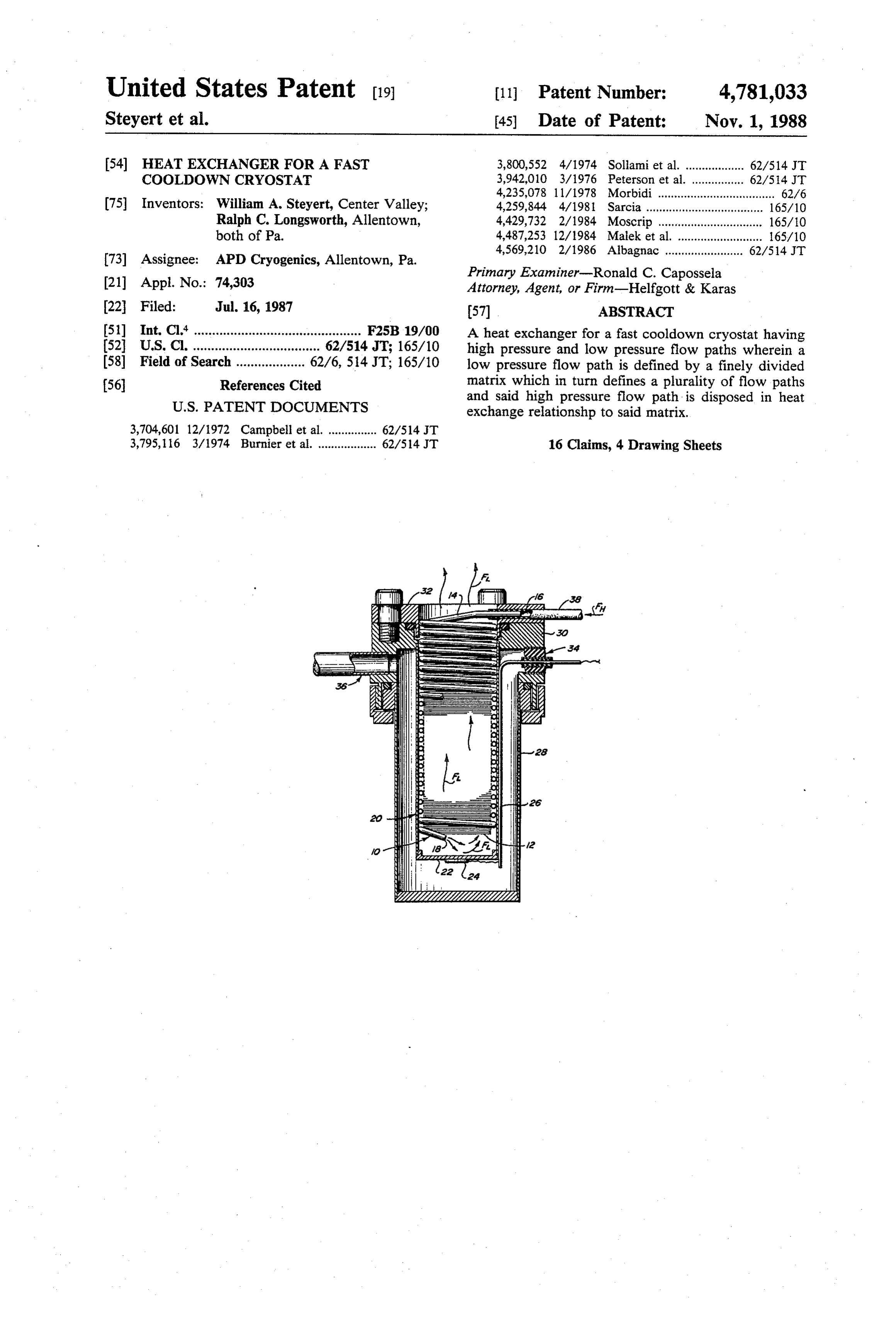
Cryostats are used in cryo-electronic systems such as FIG. 1 is an enlarged cross-sectional view of a single cooling infra-red detectors and the like. In particular, O circuit cryostat with a heat exchanger according to the there is a need for fast cooldown of detectors for missile present invention.
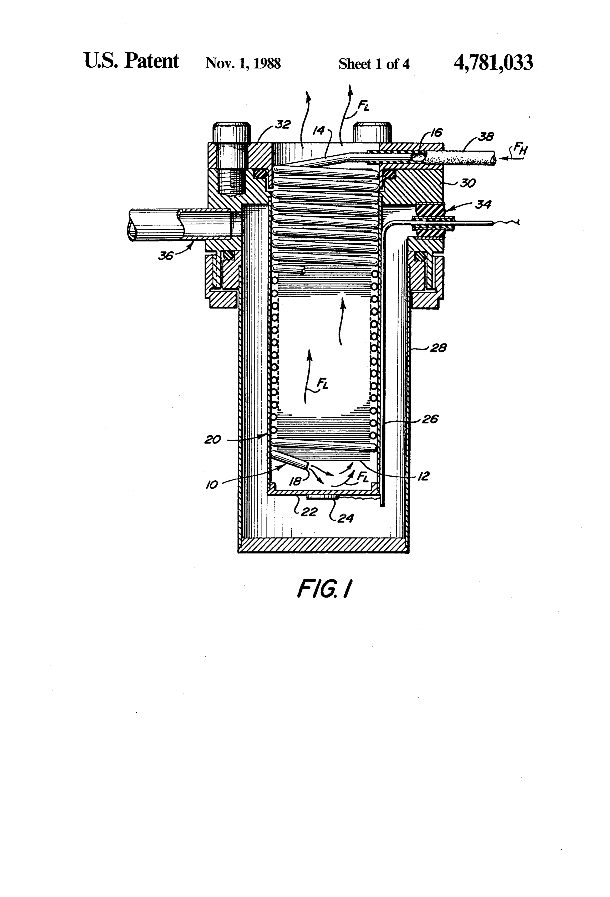
guidance systems. FIG. 2 is an enlarged cross-sectional view of a large BACKGROUND OF THE PRIOR ART diameter single circuit cryostat according to the present invention.
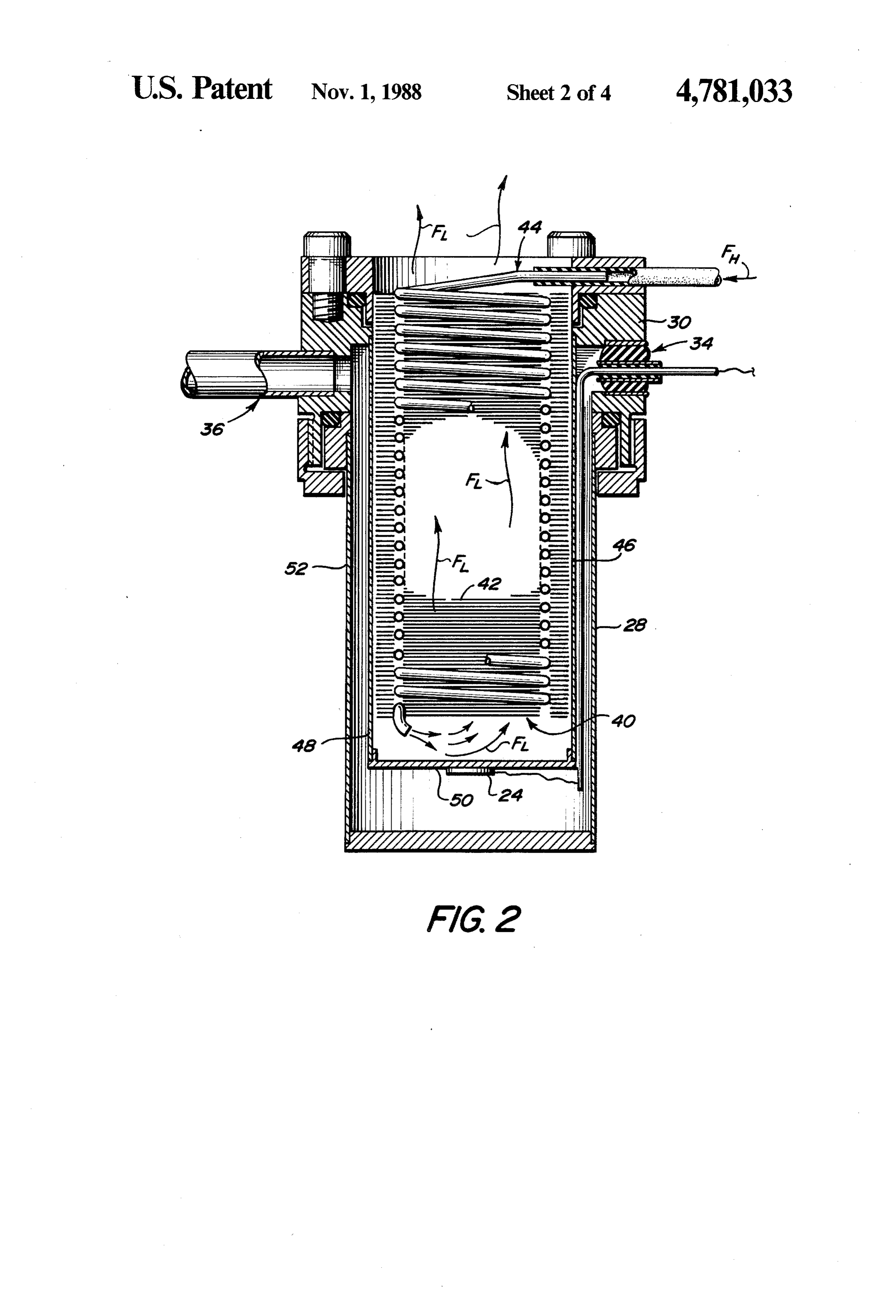
Cryostats utilizing the well-known Joule-Thomson FIG. 3 is an enlarged cross-sectional view of a cryo effect or cooling cycle are shown in U.S. Pat. Nos. 15 stat employing a dual circuit heat exchanger according 3,006,157, 3,021,683, 3,048,021, 3,320,755, 3,714,796, to the present invention.
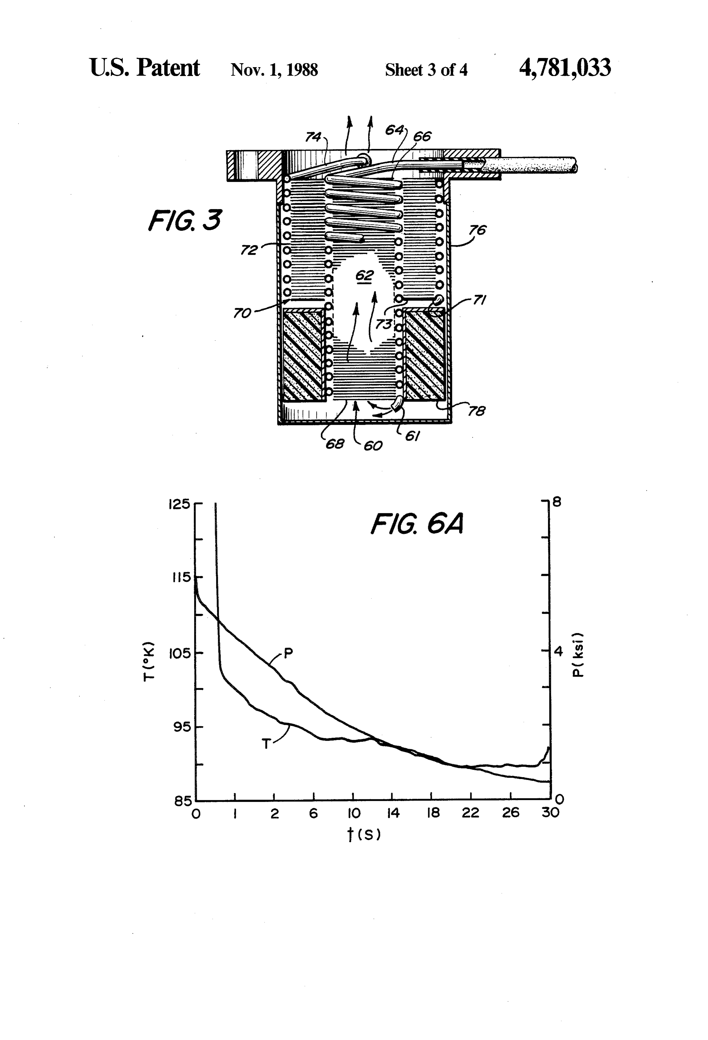
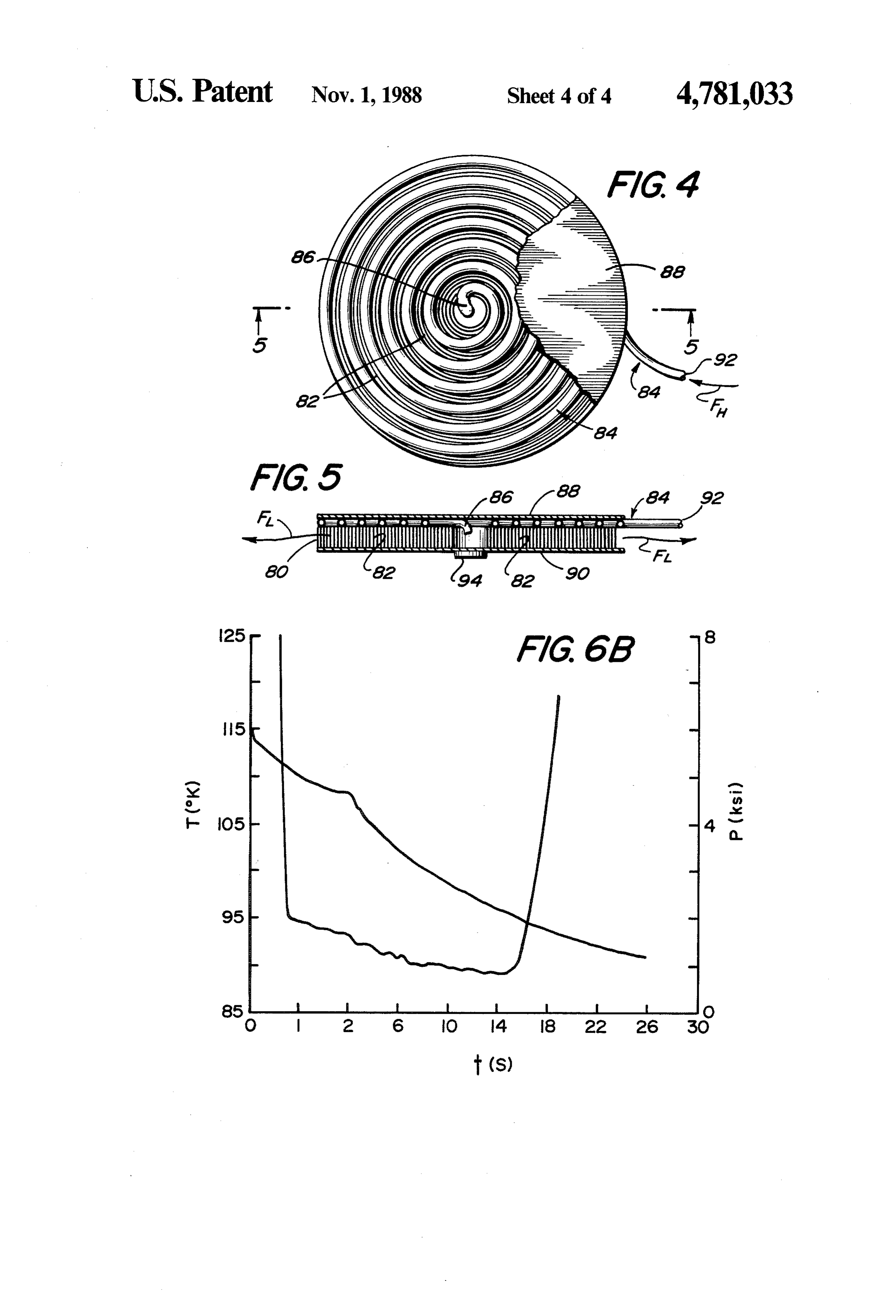
3,728,868, 4,237,699 and 4,653,284. All of the cryostats FIG. 4 is a top plan view of a cryostat employing a shown in the enumerated patents rely upon a heat ex heat exchanger according to the present invention. changer wherein high pressure fluid is conducted along FIG. 5 is a view taken along the line 5-5 of FIG. 4. a path which is in heat exchange with the cooled lower 20 FIG. 6A is a plot of temperature and pressure versus pressure gas returning after expansion through a Joule time for a cryostat employing a heat exchanger accord Thomson orifice. In all of the prior art devices, the heat ing to the prior art.
exchanger is constructed by wrapping a finned tube FIG. 6B is a plot of temperature and pressure versus around the outside of a mandrel, the finned tube termi nating in a Joule-Thomson orifice. The wrapped tube ing toforthea cryostat 25 time present employing a heat exchanger accord invention.
heat exchanger is disposed in a dewar or other sleeve so that the high-pressure gas conducted down through the DETAILED DESCRIPTION OF THE finned tube exiting the Joule-Thomson orifice which INVENTION has expanded to produce refrigeration is conducted In order to develop small lightweight Joule-Thomson countercurrently over the outside of the finned tube to 30 (J-T) effect cryostats for rapidly producing refrigera precool the in-coming high pressure gas. One of the tion of the type and quantity to immediately cool the problems with heat exchangers of this type which are infra-red embodied in cryostats is the lack of fast cool down. directed todetector in a missile at launch, attention was the heat exchanger used to convey high (response) time. This is especially a problem with cryo stats used by the military to cool infra-red detectors in 35 pressure fluid (e.g., gaseous argon, nitrogen, fluorinated guided missiles. As is well-known, guidance begins bottle hydro carbons) from a source such as a cylinder or when the missile leaves the launcher and that the missile to the Joule-Thomson orifice where the fluid must be fired as soon as possible should the need arise. after expansion and production of refrigeration at the In general, cryostats of the type employing the finned Joule-Thomson orifice is conducted over the high pres tube heat exchanger must be operational several sec sure tube to precool incoming high pressure fluid. onds before the missile is launched so that it can provide Conventional cryostats employ a heat exchanger the necessary refrigeration to cool the IR detector and generally constructed by wrapping a small diameter thus, have the missile guidance system in condition to finned tube around a mandrel. The finned tube termi guide the missile to the target. The best response time nates in a Joule-Thomson orifice. The tube and mandrel with a conventional finned tube heat exchanger has 45 structure is placed inside of a dewar or sleeve so that been to reach a temperature of 92.4 Kelvin (K.) in 2.5 high pressure fluid conducted down through the finned seconds at the Joule-Thomson orifice. tube and expanded through the Joule-Thomson orifice A heat exchanger using stacked screens was proposed is forced to leave the area of the Joule-Thomson orifice by G. Bon Mardion and G. Claudet in an article appear by flowing over the finned tube to precool the entering ing in CRYOGENICS, September 1979 entitled “A 50 high pressure fluid.
Counterflow Gas-Liquid Helium Heat Exchanger with Thus, it has been discovered that if an unfinned capil Copper Grid'. The authors do not disclose how such a lary tube of the type used in prior art heat exchangers is heat exchanger would be constructed for use in a fast placed in heat exchange (thermal contact) with a matrix cool-down cryostat. Mardion and Claudet were not of very finely divided material (e.g. wires less than 2.3 concerned with the mass of the heat exchanger because 55 mils thick in a mesh array) so that the high pressure of the wire sizes employed, thus a fast response (cool fluid is conveyed through the capillary to a Joule down) time would not be observed for this heat ex Thomson orifice and the expanded fluid is returned changer. through the finely divided material to precool the in SUMMARY OF THE INVENTION coming high pressure fluid a very rapid cooldown time 60 for a cryostat employing such heat exchanger can be
An effective heat exchanger for achieving fast cool achieved. In the preferred embodiment of the invention down in a cryostat is achieved by combining a high the finely dividend matrix is made up of a plurality of pressure fluid conduit terminating in a Joule-Thomson fine wires arrayed in the form of a layering of fine wire orifice in heat exchange relationship with a matrix of mesh screens. The use of mesh for heat transfer makes finely divided material which matrix acts as the flow 65 the refrigerator smaller and lighter than those of previ path for the warmed high pressure fluid. A particularly ous design. It is axiomatic that a lighter refrigerator effective heat exchanger is achieved when a plurality of cools faster. However, with the low-pressure gas, ade stacked fine mesh screens are combined in heat ex quate heat exchange is much more difficult. The heat
Page 7
exchange surface for the low-pressure gas must be light The materials of construction of a heat exchanger weight (therefore, high surface-to-volume ratio), have a according to the present invention are generally avail high heat transfer coefficient, and have small pressure able from custom metal houses. The materials of con drop. Tightly spaced fine copper wires are the best struction will depend upon the dimensions of the cryo media for that critical heat exchange surface. In addi stat and the performance characteristics required. tion, in order to keep the pressure drop at a minimum it Cryostats according to FIG. 1 were constructed and is essential that the low pressure gas not be confined in tested utilizing various high pressure fluids. The cryo a tight geometry where its velocity becomes large. This stats were connected to a source of high pressure gas is especially true because the pressure drop in a given via the inlet conduit 38 which is held in fluid tight rela media is proportional to its velocity to the 1.75 or sec O tion to inlet end 16 of the capillary tube 14 with fluid ond power. flows shown by arrows FH for high pressure and FL for As will be hereinafter described, the advantages of low pressure.
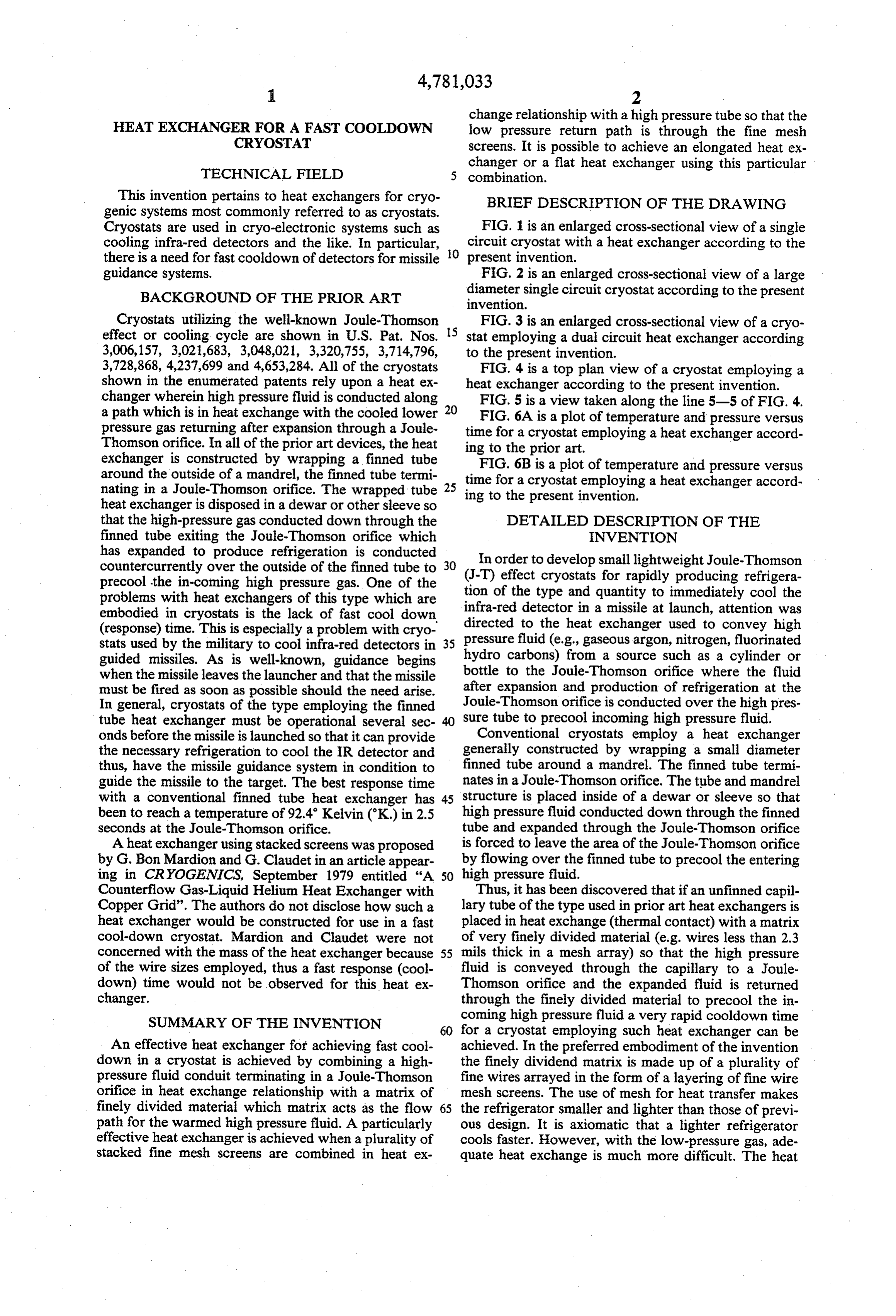
going to a fine wire matrix are manifest in several ways. As set forth in Table 1 below, two different diameter First, as the wire diameter (d) decreases, the surface-to heat exchangers were utilized in the test cryostats volume ratio goes up (this ratio can be shown to be 4/d 5 which were fabricated and tested using various high for long wires). Thus, more heat transfer area is avail pressure fluids. The test was set up as shown in FIG. 1. able for a given cool down mass. In addition, the heat transfer coefficient (h) goes up as the wire size decreases as disclosed in the publication Heat Transmission by W. Exchanger OD-in. .130 TABLE ... -->
H. McAdams published by McGraw-Hill, New York, 20 Matrix
N.Y. (1932) wherein the author shows that h equals Material copper -> --> --> -3> --> (k/d) (0.32-0.43 (dG/u)0.52 where k is the gas con Mesh 00 - - 100/150(2) 100 100 ductivity, u is its viscosity, and G its mass flow rate. # Layers 00 as re- -so -Y 50 Heat transfer coefficients in screens follow a relation Orientation() 45 - - Parallel 45° 45 similar to that in wires, except that it is more compli 25 OD-in. .08 -> -ss arris 82 .108
cated since it involves taking into consideration the Tube Materia St. St. as as ass --> s mesh size of the screen. OD-in. 013 are --> --> --> --> Referring to FIG. 1, a heat exchanger 10 according to the present invention includes a matrix 12 which can be iTurns 23 23 23 23 23 34 constructed from a plurality of fine wire mesh screens 30 Co - /M(3) Orifice 2.5 - --> -wis ar area
of a highly conductive material such as copper. Screens Gas N2 Ar CF4. Air Ar Air having a mesh size of approximately 100 have been Performance found to be particularly effective, but the mesh size can NTU(4) 4. 5.2 3.9 6.2 7.3 7.8 be varied depending upon the performance characteris CDT (5) 2.4 .3 .1 .3 .3 3 tics for the desired cryostat. Preferably the screens are 35 T(6)K 84 94 151 96 89 96 layered and each screen is oriented 45 to its neighbor to adjacent (45 means that the wires in each layer of screen are rotated 45 with respect to the layers.
define the flow path as shown by the arrows in FIG. 1. (A 100-mesh
While the preferred embodiment employes fine wire screens parallel.screen is alternated with a 150-mesh screen with wires in adjacent mesh screens, other finely divided materials such as (Co = =flownumber rate measured at room temperature with 1000 psi N2. layered wires, sintered porous metals and the like can be (NTU of transfer units. (CDT = calculated cooldown time, with very light cold end caps.
used in place thereof. Disposed around and fixed to the (T = calculated temperature at cooldown. matrix 12 in good heat exchange relation therewith is a small diameter capillary tube 14. The capillary tube 14 The inlet gas pressure for the test set up was 6,000 psi is preferably fabricated from an alloy of copper having at the commencement of the test. It is important to note good thermal conductivity. Capillary tube 14 is dis 45 that it is not necessary to cool the cold end 18 of the posed in such a manner to define an inlet or warm end heat exchanger all the way to 87 K. or 77 K. in order 16 and an outlet or cold end 18 for the heat exchanger to produce refrigeration at 87 K. or 77 K. at the bot 10. Conventionally cold end 18 terminates in a Joule tom of the sleeve with argon or nitrogen gas respec Thomson (J-T) orifice (not shown) as is well known in tively. When the 6,000 psi fluid reaching the Joule the art. 50 Thomson orifice on the cold end 18 of the heat ex As shown in FIG. 1, a heat exchanger 10 according to changer 10 is cooled to 220 K. or 180' K. with argon or the present invention can be disposed inside of a stain nitrogen, it produces a mixture of the respective lique less steel sleeve 20 having an end cap 22 on one end so fied gas and gaseous argon or nitrogen upon expansion that when the heat exchanger 10 is inserted in the sleeve to low pressure. With this phenomenon present the there is a space between the cold end 18 of the heat 55 requirement for the most rapid cooldown is that the exchanger and the cap 20 for accumulation of liquefied 6,000 psi fluid, as it expands to lower pressure, not be in and/or cold fluid. As shown in FIG. 1, the cap 22 in thermal contact with the cold end of the refrigerator. cludes a temperature sensor (or detector) 24 which is The cold end of the refrigerator is still at 229°K. or 180° connected via conventional electrical feeds 26 to a tem K. and will heat the expanding fluid which is cooling to perature monitoring device (not shown). The sleeve 20 87 or 77' K. respectively. This undesired heating will and heat exchanger 10 which define a cryostat are dis prevent the cooldown of the bottom of the sleeve 20 posed inside of a vacuum housing 28 which in turn is until the cold end of the refrigerator has cooled to al fixed to a flange 30 which in turn is held in vacuum tight most 87 or 77 K. thus the heat exchanger must be relationship to a test adaptor 32. Vacuum housing 28 configured as shown.
includes suitable feed through ports 34 for the electrical 65 Referring to FIGS. 6A and 6B respectively there is conduits and a vacuum pump out port 36 to evacuate shown a plot of temperature and pressure versus time the housing to thus measure the effectiveness of the heat for, in the case of FIG. 6A, a cryostat with a conven exchanger 10. tional finned tube heat exchanger such as disclosed in
Page 8
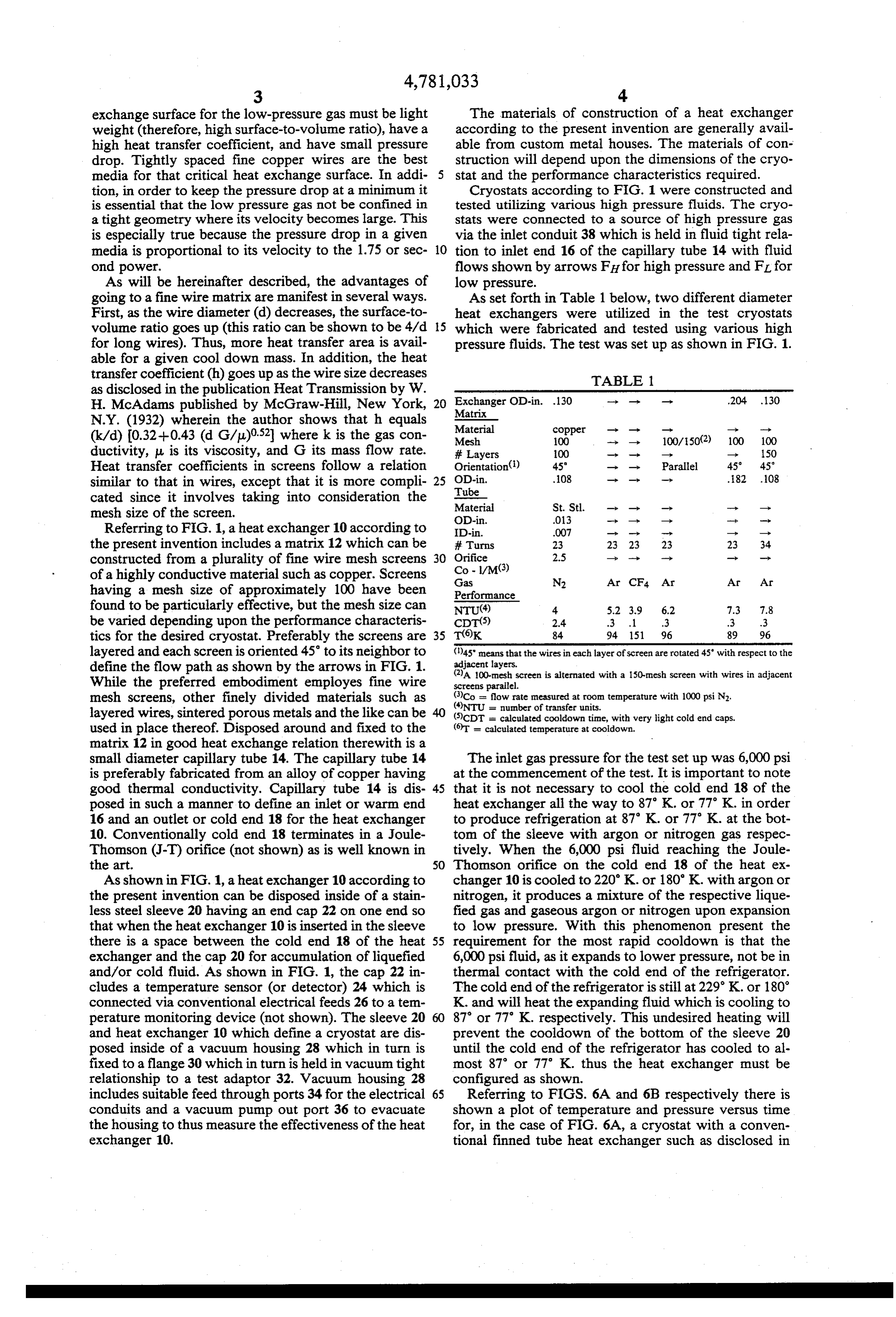
any of the cited prior art and, in the case of FIG. 6B, a heat exchanger 60 by utilizing various combinations of cryostat with a heat exchanger according to the present gases (cryogens) as set forth in Table 2. invention. In the case of the finned tube device (FIG. TABLE 2 6A) the heat exchanger had an outside diameter of 0.130 Test No. Capillary 64 Capillary 74 Minimum Temp K. inches and was 1.2 inches long and the cryostat of FIG. 5 6B was of the same diameter with a length of 0.36 2
inches. In both cases the tests were run and temperature 3 CF3Cl N2 83 measured with no vacuum jacketing of the heat ex 4. CF4 N2 83 changer. As is apparent from a comparison of FIGS. 6A 5 CF4 N2/Ne 75 and 6B the cryostat with the heat exchanger according 10 76 AIR AR N2/Ne
to the present invention (FIG. 6B) achieves a tempera 8 N2 Ne 32 ture of 95 K. in slightly less than 1 second whereas the 9 AIR H2 25 cryostat of the prior art requires almost 4 seconds to 10 N2 H2 25 achieve the same temperature. Therefore, a fast cool down cryostat can be achieved by embodying the heat 15 Referring to FIGS. 4 and 5 the heat exchanger ac exchanger of the present invention. cording to the present invention can be embodied in the Referring to FIG. 2 there is shown a large diameter form of a flat disc for embodiment into a low profile cryostat wherein the heat exchanger 40 is constructed configuration. As shown in FIGS. 4 and 5 the heat by utilizing a plurality of stacked inner screens 42 20 exchanger 80 is constructed by providing an annulus of around which is disposed the capillary tube 44. Dis fine mesh screens 82 which can be fabricated by wrap posed around the capillary 44 is a second set of stacked ping the screening around a removeable mandrel. Dis screens 46. The materials of construction can be the posed along one side of the annulus of screens 82 is a same for the heat exchanger of FIG. 2 as for the heat capillary 84 which terminates in a Joule-Thomson ori exchanger of FIG.1. The heat exchanger of FIG. 2 can fice 86 inside of the annulus of screens 82. The screen be disposed within a stainless steel sleeve 48 which has 25 and capillary construction is closed by a pair of spaced an end cap 50 and which can be disposed in a vacuum apart stainless steel discs 88 and 90 so that high pressure housing 52 to be tested in accordance with the test fluid shown by arrow FH conducted from the inlet 92 of method of the device of FIG. 1. The device of FIG. 2 capillary 84 to the Joule-Thomson orifice 86 flows radi shows fluid flow using the same nomenclature as in 30 ally outwardly between discs 88 80 as shown by the FIG. 1. Comparatively speaking the heat exchanger of arrow FL. The screening 82 can be achieved by spirally FIG. 1 would have an outside diameter of 0.130 inches winding one hundred mesh copper screen around a and a length of 0.40 inches whereas the heat exchanger mandrel. As with the other heat exchangers final assem of FIG. 2 can have an outside diameter of 0.326 inches bly can be by any conventional technique such as fur and a length of 0.60 inches. 35 nace brazing of the assembly. The assembled device of A two-stage cryostat according to the present inven FIGS. 4 and 5 can be used with a detector to be cooled tion is shown in FIG. 3 wherein there is employed a first placed as shown as item 94.
heat exchanger 60 which is constructed by stacking a It is well known that in conventional infrared detec plurality of screens 62 around which is disposed a capil tor systems approximately 5 to 10 seconds are required lary 64 such as shown and described in relation to FIG. to cool the detector to operating temperatures with 1. conventional Joule-Thomson cryostats. It is very desir Disposed around a portion of the first heat exchanger able to reduce this cooldown time to the neighborhood 60 is a second heat exchanger 70 which is constructed of 1 second at temperatures of approximately 90 kelvin from a plurality of stacked annular screens 72 around so that the infrared detector is ready to function imme which is disposed a capillary 74. The second heat ex 45 diately upon being needed. Thus it would be possible to changer 70 is constructed so that its total length is less eliminate the need for constant refrigeration in order to than that of heat exchanger 60 and it encircles only a keep a device such as a missile in the ready fire condi portion of heat exchanger 60 from the warm end 66 tion. This has been achieved with the heat exchanger of toward the cold end 68 of the heat exchanger 60. The the present invention.
dual heat exchanger 60-70 can be disposed inside of a 50 Having thus described our invention what is desired stainless steel sleeve 76. The projecting end of heat to be secured by Letters Patent of the United States is exchanger 60 can be kept in position inside sleeve 76 by set forth in the appended claims. a foam spacer 78. We claim:
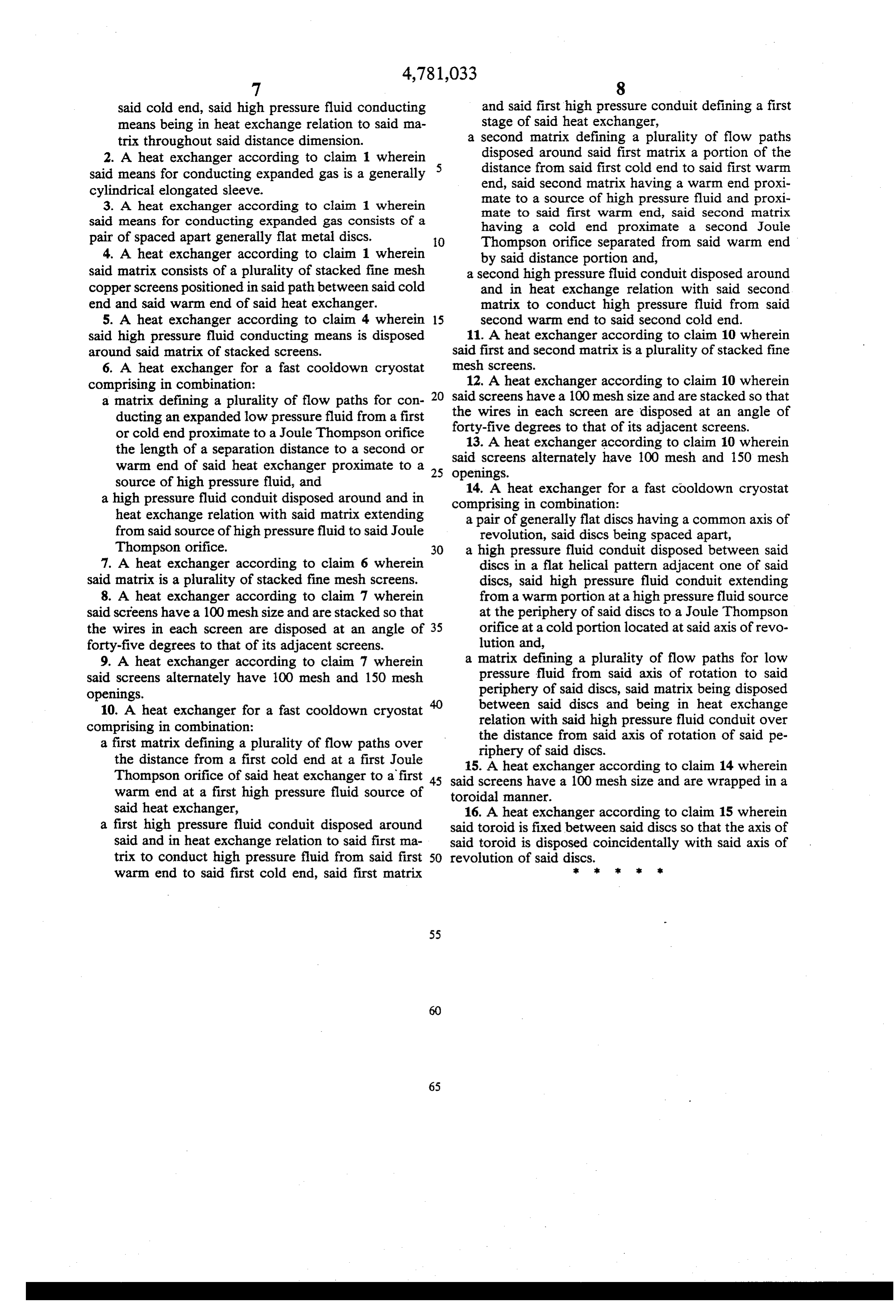
The dual heat exchanger of FIG. 3 including a first 1. A heat exchanger for a fast cooldown cryostat JT orifice 61 for tube 64 of heat exchanger 60 and a 55 having in at least one stage the combination of second JT orifice 71 for tube 74 of heat exchanger 70 a cold end located proximate to a Joule Thompson with the first heat exchanger capillary 64 connected to orifice, a source of high pressure fluid such as neon at 100 atmo a warm end located proximate to a source of high spheres and a second capillary 74 connected to a source pressure fluid, said cold end and said warm end of nitrogen at 400 atmospheres with both gases being at 60 being separated by a distance dimension, a temperature of approximately 300 kelvin (K.) will means for conducting expanded gas from said Joule produce a temperature of approximately 30' kelvin at Thompson orifice the length of said distance di the bottom 68 of heat exchanger 60 when tested as mension to said warm end, said conducting means shown. A temperature of approximately 83' kelvin is comprising a matrix defining a plurality of paths for achieved at the bottom of a device according to FIG. 3 65 said expanded gas from said Joule Thompson ori if capillary 64 is connected to N2 and capillary 74 is fice to said warm end, and connected to CF4. A device according to FIG. 3 can means for conducting said high pressure fluid from produce different temperatures at the cold end 68 of said warm end to said Joule Thompson orifice at
Page 9
said cold end, said high pressure fluid conducting and said first high pressure conduit defining a first means being in heat exchange relation to said ma stage of said heat exchanger, trix throughout said distance dimension. a second matrix defining a plurality of flow paths 2. A heat exchanger according to claim wherein disposed around said first matrix a portion of the said means for conducting expanded gas is a generally distance from said first cold end to said first warm cylindrical elongated sleeve. end, said second matrix having a warm end proxi 3. A heat exchanger according to claim 1 wherein mate to a source of high pressure fluid and proxi said means for conducting expanded gas consists of a mate to said first warm end, said second matrix having a cold end proximate a second Joule pair of spaced apart generally flat metal discs. O Thompson orifice separated from said warm end 4. A heat exchanger according to claim 1 wherein by said distance portion and, said matrix consists of a plurality of stacked fine mesh a second high pressure fluid conduit disposed around copper screens positioned in said path between said cold and in heat exchange relation with said second end and said warm end of said heat exchanger. matrix to conduct high pressure fluid from said 5. A heat exchanger according to claim 4 wherein 15 second warm end to said second cold end. said high pressure fluid conducting means is disposed 11. A heat exchanger according to claim 10 wherein around said matrix of stacked screens. said first and second matrix is a plurality of stacked fine 6. A heat exchanger for a fast cooldown cryostat mesh screens.
comprising in combination: 12. A heat exchanger according to claim 10 wherein a matrix defining a plurality of flow paths for con 20 said screens have a 100 mesh size and are stacked so that ducting an expanded low pressure fluid from a first the wires degrees in each screen are disposed at an angle of or cold end proximate to a Joule Thompson orifice forty-five to that of its adjacent screens. the length of a separation distance to a second or said13.screens
A heat exchanger according to claim 10 wherein warm end of said heat exchanger proximate to a 25 openings. alternately have 100 mesh and 150 mesh source of high pressure fluid, and 14. A heat exchanger for a fast cooldown cryostat a high pressure fluid conduit disposed around and in comprising in combination:
heat exchange relation with said matrix extending a pair of generally flat discs having a common axis of from said source of high pressure fluid to said Joule revolution, said discs being spaced apart, Thompson orifice. 30 a high pressure fluid conduit disposed between said 7. A heat exchanger according to claim 6 wherein discs in a flat helical pattern adjacent one of said said matrix is a plurality of stacked fine mesh screens. discs, said high pressure fluid conduit extending 8. A heat exchanger according to claim 7 wherein from a warm portion at a high pressure fluid source said screens have a 100 mesh size and are stacked so that at the periphery of said discs to a Joule Thompson the wires in each screen are disposed at an angle of 35 orifice at a cold portion located at said axis of revo forty-five degrees to that of its adjacent screens. lution and, 9. A heat exchanger according to claim 7 wherein a matrix defining a plurality of flow paths for low said screens alternately have 100 mesh and 150 mesh pressure fluid from said axis of rotation to said openings. periphery of said discs, said matrix being disposed 10. A heat exchanger for a fast cooldown cryostat 40 between said discs and being in heat exchange comprising in combination: relation with said high pressure fluid conduit over a first matrix defining a plurality of flow paths over the distance from said axis of rotation of said pe the distance from a first cold end at a first Joule riphery of said discs.
15. A heat exchanger according to claim 14 wherein
Thompson orifice of said heat exchanger to a first 45 said screens have a 100 mesh size and are wrapped in a warm end at a first high pressure fluid source of toroidal manner.
said heat exchanger, 16. A heat exchanger according to claim 15 wherein a first high pressure fluid conduit disposed around said toroid is fixed between said discs so that the axis of said and in heat exchange relation to said first ma said toroid is disposed coincidentally with said axis of trix to conduct high pressure fluid from said first 50 revolution of said discs.t :
warm end to said first cold end, said first matrix
Provenance
- Collection
- Cited prior art
- Original PDF
- patentimages.storage.googleapis.com →
- Filed
- 1987-07-16
- Pages
- 9
- Method
- pdftotext (the PDF's own text layer) + pdftoppm 300dpi page scans
- Source
- Google Patents bibliographic record
- Granted
- 1988-11-01
- Inventors
- William A. Steyert; Ralph C. Longsworth; Sumitomo SHI Cryogenics of America Inc
- Transcribed from
- patentimages.storage.googleapis.com →