patent · US4375806
Heating system
8 March 1983
Page 1 — bibliographic record
United States Patent (19. 11 4,375,806 Nishman
54 HEATING SYSTEM Primary Examiner-James C. Yeung 75) Inventor: Paul J. Nishman, Seattle, Wash. Attorney, Agent, or Firm-Seed, Berry, Vernon & Baynham (73) Assignee: Spencer Products Company, Seattle, (57) ABSTRACT Wash.
A heating system utilizing solar panels and buried (21) Appl. No.: 187,314 ground conduits to collect and store heat which is deliv 22 Filed: Sep.15, 1980 ered to a heat-pump heat exchanger. A heat-distribution fluid continuously circulates through a ground circuit 51) Int. Cl.................................................. F24J 3/02 to transfer heat from the ground to the heat exchanger. 52 U.S. Cl......... . . . . . . . . . . . . . . . . . . . . . . . . . 126/436; 126/422; The ground circuit includes a length of buried ground 126/435; 126/400; 62/235.1 conduit, a pump, a check valve and the heat exchanger.
(58) Field of Search ............... 126/430, 435, 436, 400, A solar circuit, including a solar panel and a second 126/422; 237/2. B; 165/DIG. 2, 29, 104M, 18, pump, is connected in parallel with the check valve so 104 S; 62/235.1, 238 E that the distribution fluid transfers solar heat to the heat exchanger for utilization and to the ground conduit for (56) References Cited storage when the second pump is energized. A thermo
3,262,493. 7/1966. Hervey .................................. 165/18 second pump only when the temperature differential 4,010,731.3/1977. Harrison ............................. 126/400 between the solar panel inlet and outlet temperatures 4,049,407. 9/1977. Bottum ............................... 62/238.6 exceeds a predetermined value and the ground tempera 4,063,546. 12/1977 Schmid ................................ 126/400 ture is less than a predetermined value. Consequently, 4,205,718, 6/1980 Balch..... 165/48 S the distribution fluid flows through the solar panel only 4,277,946 7/1981. Bottum .. ... 165/45 when the panel is capable of supplying significant heat 4,291,833.9/1981 Franchina ........................... 237/2 B to the remainder of the system without causing exces FOREIGN PATENT DOCUMENTS sive drying of the ground.
2803458 8/1979 Fed. Rep. of Germany. 126/436 16 Claims, 1 Drawing Figure
Page 2
Drawing sheet — no readable text.
Page 3
manner which prevents detrimental drying of the
HEATING SYSTEM ground. As a result, the efficiency of these heating sys tems is far from optimum.
BACKGROUND OF THE INVENTION
1. Field of the Invention . . . . . . SUMMARY OF THE INVENTION This invention relates to solar heating systems and, It is an object of the invention to provide a ground more particularly, to a solar heating system which de conduit-enhanced solar heating system which circulates livers heated distribution fluid directly to a heat-pump a heat-distribution fluid directly to a heat-utilization heat exchanger or a ground conduit without causing 10 device without the use of large, expensive and complex excessive drying of the ground surrounding the conduit. heat-storage devices located between the ground con 2. Description of the Prior Art duit, solar panels and heat-utilization device. Heating systems utilizing solar heat collected by solar It is another object of the invention to operate a panels have long been in common use. In these conven ground conduit-enhanced solar heating system in a itional systems, a fluid flows through the solar panel, 15 manner which does not degrade the advantage of such which has a relatively large surface area to maximize enhancement by removing moisture from the ground. the quantity of solar heat absorbed by the distribution These and other objects of the invention are provided fluid. The heated distribution fluid then flows to a heat by a heating system utilizing a heat exchanger, which storage device, which is typically a large insulated res may be part of a heat pump, including first and second ervoir of the distribution fluid or a large quantity of 20 chambers having respective inlets and outlets. A ground heat-storage material, such as rocks, through which the conduit imbedded in soil has its ends connected be distribution fluid flows. Heat is then transferred to a tween the inlet and outlet of the first fluid chamber, and heat-utilization device, either directly, by the distribu tion fluid, or indirectly, through a heat exchanger. aflow pump is selectively energized to cause the fluid to the ground conduit. A solar panel having fluid
These conventional solar heating systems generally 25 flowing utilize a differential thermostat which causes the distri the heatedthrough fluid passages absorb solar heat, and fluid is directed to the first chamber of the bution fluid to flow only when the temperature of the heat exchanger for utilization and to the ground conduit fluid leaving the solar panel is significantly greater thanfor storage. A temperature sensor measures the temper the temperature of the fluid in the heat-storage device.
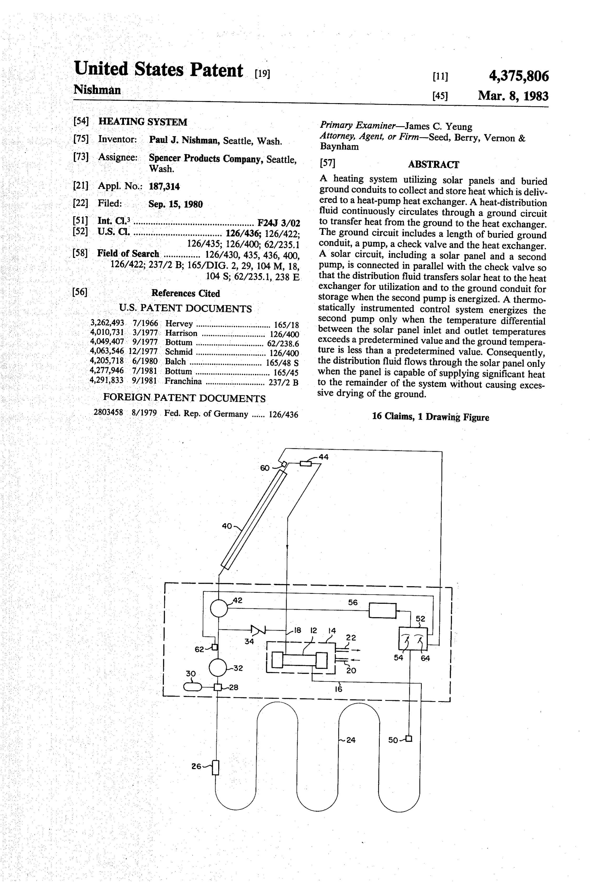
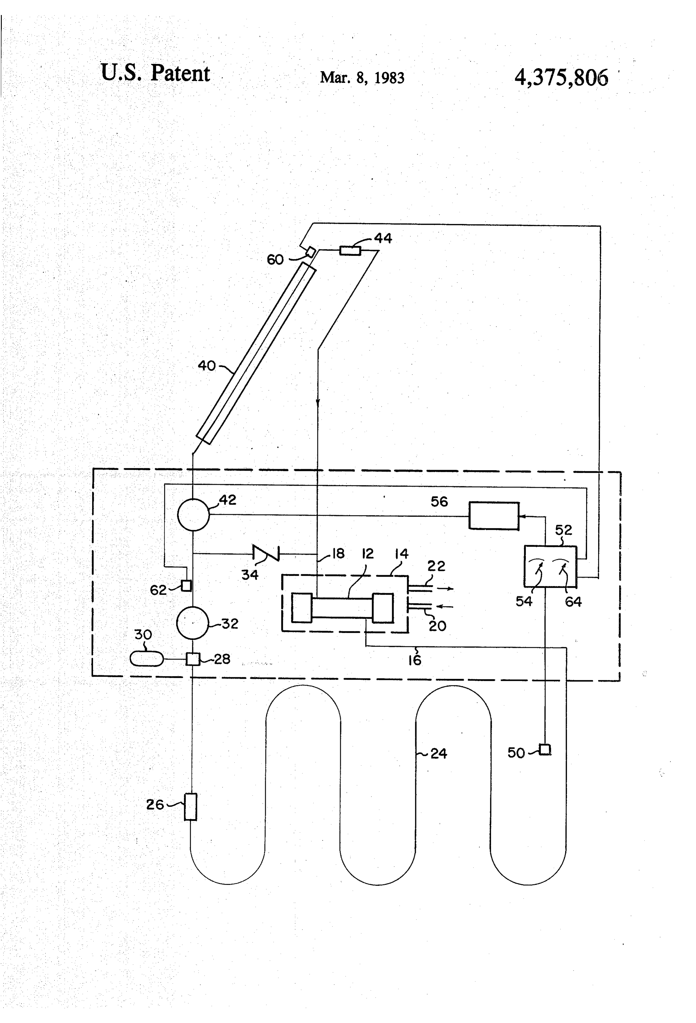
Attempts have been made to supplement the effi ature of the soil adjacent the ground conduit and allows ciency of solar heating systems by utilizing the ground 30 fluid to flow through the solar panels only when the temperature of the ground is below a predetermined as a source of heat and as a means of storing heat gener value, thereby preventing the removal of moisture from iated by the solar panels. Accordingly, a length of con duit is buried in the ground and the distribution fluid the ground. The ground conduit forms a part of a ground circuit including a pump and a check valve recirculates through the conduit and the heat-storage device. The heat-storage device thus acts as a manifold, 35 connected in series with the first chamber of the heat receiving distribution fluid from and discharging distri exchanger. The solar panel forms a part of a solar panel bution fluid to the solar panels, ground conduit and circuit including a second pump connected in parallel heat-utilization device. Although such enhancements with the check valve. Consequently, heat-distribution have, in fact, improved the efficiency of solar heating fluid flows directly to the heat exchanger from the solar systems, it has not been heretofore recognized that the panel and the ground conduit instead of first passing efficiency of such systems has not yet been optimized. through a conventionally used heat-storage device. The The quantity of heat transferred from the ground to the check valve allows the distribution fluid to circulate ground conduit is a function of the temperature of the through the heat exchanger without flowing through ground, the "thermal mass” or specific heat of the the solar panel, but it prevents the fluid flowing through ground, and the thermal conductivity of the ground. 45 the solar panel from flowing through the heat ex The ground is typically quite moist so that its thermal changer without also flowing through the ground con mass and thermal conductivity are fairly high. Thus, as duit circuit. A differential temperature sensor actuates the temperature of the ground is raised, a substantial the pump for the solar panel circuit only when the quantity of heat is stored. High ground moisture also temperature differential between the fluid leaving the causes the thermal conductivity to be fairly high so that 50 solar panel and the fluid entering the panel exceeds a a relatively small temperature difference between soil predetermined value corresponding to the temperature and ground conduit is required to transfer a given differential at which the solar panel conveys significant amount of heat, and the effective heat-drawing radius of heat to the remainder of the system. the conduit is relatively high. However, as the tempera ture is raised further, beyond a predetermined value 55 BRIEF DESCRIPTION OF THE DRAWING which varies from area-to-area, the increased tempera The FIGURE is a schematic of the ground conduit ture removes moisture from the, ground. Thereafter, enhanced solar heating system of the present invention. although the temperature of the ground continues to DETAILED DESCRIPTION OF THE increase, its thermal mass markedly decreases so that INVENTION the quantity of heat stored in the ground actually de creases with an increase in temperature. More impor The heating system, as illustrated in FIG. 1, is tantly, however, the reduced thermal conductivity ef. adapted to add heat to a distribution fluid flowing from fectively insulates the conduit from the ground. There a heat exchanger 12, which may form part of a heat after, a greater temperature differential between con pump 14, through conduit 16 so that the distribution duit and ground is required to transfer a given amount 65 fluid flowing into the heat exchanger 12 through con of heat, and heat is absorbed from a much smaller area. duit 18 is of a higher temperature. In a typical heat Conventional solar heating systems utilizing ground pump, a refrigeration fluid enters the heat pump conduit enhancement have notheretofore operated in a through conduit 20, and it is then allowed to expand,
Page 4
thereby dropping in temperature. The cooled refrigera often generates substantially more heat than is absorbed tion fluid then flows through the heat exchanger 12 by the heat exchanger 12. Under these circumstances, where its temperature is raised, and the temperature of solar heat from the panel 40 is transferred to the ground the distribution fluid is correspondingly lowered. Fi adjacent the ground coil 24 so that solar heat is stored in nally, the refrigeration fluid flowing from the heat ex the ground for subsequent utilization. . .. .. . changer 12 is compressed, thereby substantially raising Although ground coils have been used for storing its temperature, and this high-temperature refrigeration solar radiation generated by a solar panel, it has not fluid flows through conduit 22 to a heat-utilization de heretofore been recognized that the quantity of heat vice, such as a radiator. The efficiency of the heat pump stored in the ground can actually decrease as the tem increases as the temperature of the distribution fluid 10 perature of the ground increases beyond a certain point. entering the heat exchanger 12 through conduit 18 in The quantity of heat stored in the ground is propor creases. Consequently, it is highly desirable to add as tional to the product of the "thermal mass” or specific much heat as possible to the distribution fluid between heat of the ground and its temperature. Thus, as the outlet conduit 16 and inlet conduit 18. solar heat increases the temperature of the ground, the The distribution fluid flowing from the heat ex 15 quantity of heat thereby stored increases. The ground, changer 12 through conduit 16 enters a length of con being somewhat moist, normally has a fairly high ther duit 24 buried in the ground at a suitable depth, such as, mal mass in that it is a fairly good heat-storing material. for example, three feet. As the distribution fluid flows However, as the temperature of the ground increases through the ground conduit 24, heat from the ground is beyond a certain point, the heat removes moisture from transferred to the distribution fluid so that the tempera 20 the ground so that the thermal mass decreases. As the ture of the distribution fluid flowing out of the ground temperature continues to increase, the heat stored in the conduit 24 is higher than the temperature of the fluid ground actually decreases because the decrease in ther flowing into the ground conduit 24. The distribution mal mass of the ground more than makes up for the fluid then passes through a conventional air purger 26 increase in temperature. The ground temperature at which removes air entrained in the distribution fluid 25 which significant moisture removal occurs varies with and then flows through a second air purger 28 con season and location. However, in the Pacific Northwest nected to an expansion tank 30 just upstream from a during the winter, removal of ground moisture starts at conventional pump 32. The expansion tank 30 allows about 45 F.
the conduits and heat exchanger to remain full of distri The quantity of heat stored in the ground is only one bution fluid as the distribution fluid contracts respon 30 factor in determining the quantity of heat which is sive to cooling. The pump 32 causes the distribution transferred to the ground conduit. As even more impor fluid to circulate through the heat exchanger 12, ground tant consideration is the thermal conductivity, or insula conduit 24, and a conventional check valve 34 posi tive effect, of the ground. Moist soil has a relatively tioned downstream from the pump 32. The check valve good conductivity. Consequently, a given quantity of 34 allows fluid to flow in the direction indicated but 35 heat is transferred to the ground conduit at a relatively prevents flow in the opposite direction, for a purpose low temperature differential between the ground and explained hereinafter. The heat exchanger 12, ground ground conduit. Also, the heat is transferred to the conduit 24, pump 32 and check valve 34 thus form a conduit from a larger area. Dry soil, on the other hand, ground circuit through which distribution fluid contin effectively insulates the conduit from the ground so that uously recirculates. a substantially higher temperature differential between As mentioned above, it is highly advantageous for a the ground and ground conduit is required to transfer a large amount of heat to be added to the distribution given quantity of heat, and the heat is transferred from fluid before it enters the heat exchanger 12. Conse a substantially smaller area. - quently, a solar panel circuit is provided for boosting In accordance with one important aspect of the in the temperature of the distribution fluid when appropri 45 vention, a temperature sensor 50 is positioned in the ate solar conditions are present. The solar panel circuit ground adjacent the inlet to the ground conduit 24 for includes a conventional solar panel 40 having a rela measuring the temperature of the ground. The sensor 50 tively large area and a large number of spaced-apart is connected to a conventional thermostat 52 having an fluid channels through which the distribution fluid actuator 54 for selecting a manually adjustable setpoint. flows. The distribution fluid thus absorbs solar heat as it 50 The thermostat 52 is connected to a conventional motor flows through the solar panel 40. A second pump 42 is controller 56 which prevents the pump 42 from being provided to cause the distribution fluid to flow through energized whenever the ground temperature, as mea the solar panel 40 and another air purger 44 removes air sured by the sensor 50, exceeds the set point of the from the distribution fluid exiting the solar panel 40. thermostat 52. The solar panel 40 thus provides heat to The check valve 34 prevents the distribution fluid from 55 the ground coil 24 until the ground reaches a tempera flowing in a circular path through the solar panel 40, ture at which significant drying occurs. Thereafter, the check valve 34 and pump 42. Instead, the distribution distribution fluid bypasses the solar panel 40 by flowing fluid flowing from the solar panel 40 must flow through through the check valve 34.
the heat exchanger 12 and ground conduit 24. A sole The ability of the solar panel 40 to transfer heat to the noid valve (not shown), which is closed when fluid is to 60 heat exchanger 12 and ground depends, of course, upon flow through the solar panel 40, may be used instead of a number of circumstances, such as the intensity of the the check valve 34, thereby allowing the second pump sunlight striking the panel 40 and the temperature of the 42 to be eliminated. However, the load on the pump 32 ground adjacent the ground conduit 24. It is thus impor would then vary as the solenoid valve was actuated, tant to monitor the temperature of the distribution fluid producing an undesirable variation in the flow rate of 65 flowing from the solar panel 40 and the temperature of the distribution fluid through the pump 32. the distribution fluid in or downstream from the ground The solar panel 40 adds substantial heat to the distri coil 24 to ensure that the solar panel 40 is capable of bution fluid, even under partly cloudy conditions, and it generating usable heat. Accordingly, a conventional
Page 5
temperature sensor 60, such as a thermistor, is mounted ture indication from said temperature-sensing means is at the outlet from the solar panel 40 for generating an below a predetermined value and for causing said distri electrical indication of the temperature of the distribu bution fluid to bypass said solar panel when the temper tion fluid from the solar panel 40. Another temperature ature indication from said temperature-sensing means is sensor 62, which may also be a conventional thermistor, above a predetermined value, said predetermined value is mounted at the outlet of the pump 32 for measuring corresponding to the temperature at which significant the temperature of the distribution fluid leaving the drying of said soil occurs, whereby heat from said solar ground coil 24. The temperature sensors 60,62 are also panel is stored in said soil without significantly reducing connected to the thermostat 52. The thermostat 52 is a the thermal mass and thermal conductivity of said soil conventional differential thermostat sold by Heliotrope 10 by removing moisture therefrom. General which generates an output whenever the tem 2. The heating system of claim 1 wherein said prede perature: measured by sensor 50 is below a predeter termined temperature corresponds to approximately 45° mined value, as determined by set point adjustment 54, F.
and the temperature differential, as measured by sensor 3. The heating system of claim 1 wherein said control 60 and sensor 62, exceeds a predetermined value, as 15 means comprise selectively actuated second pump determined by set point adjustment 64. The pump 42 is means having a first port connected to one end of said thus energized for causing distribution fluid to flow solar panel fluid passages, a check valve connected through the solar panel 40 whenever the temperature of between the other ends of said solar panel fluid passages the ground is below the temperature at which signifi and a second fluid port of said second pump means, and cant drying occurs and the temperature of the distribu 20 switch means for actuating said second pump means tion fluid flowing from the solar 40 exceeds the temper when the temperature indication from said temperature ature of the fluid flowing from the ground conduit 24 by sensing means is below said predetermined value, said a predetermined, amount. In practice, a temperature check valve allowing said distribution fluid to bypass differential set point of 10° F has been advantageously said solar panel when said second pump means is not 25 actuated while preventing circuitous flow through said
An important advantage of the inventive heating solar panel, check valve and second pump means when system is its simplicity and low cost, Conventional said second pump means is actuated so that said distri ground conduit-enhanced solar heating systems have bution fluid flows through said solar panel. heretofore utilized a large heat-storage device, such as a 4. The heating system of claim 1 wherein said control large tank or mass of rocks, as a manifold which com 30 means comprise valve means for selectively shunting municates separately wtih the solar panel, ground con the fluid passages of said solar panel, and switch means duit and heat exchanger. In these conventional systems, for actuating said valve means when the temperature the distribution fluid flows directly from the solar panel indication from said temperature-sensing means is to the heat-storage device, from the heat exchanger to above said predetermined value.
the heat-storage device, and from the ground conduit to 35 5. The heating system of claim 1, further including the heat-storage device. This system requires expensive fluid temperature-sensing means for providing an indi and complex controls for regulating the flow of the cation of the temperature of distribution fluid flowing solar panel circuit, ground conduit circuit and heat out of said ground conduit, and panel temperature-sens exchanger circuit individually, the only common ele ing means for providing an indication of the tempera ment to the circuits being the heat-storage device. The ture of said solar panel, said control means receiving inventive heating system, by allowing the distribution said fluid temperature and panel temperature indica fluid to flow directly from the solar panel, through the tions and preventing said distribution fluid from flowing heat exchanger, 12 and ground coil 24, avoids the ex through said solar panel unless said panel temperature pense, complexity and size of these conventional heat indication is larger than said fluid temperature indica ing systems. The system is thus markedly less expensive 45 tion by a predetermined temperature differential. and space-consuming than conventional systems, and it 6. The heating system of claim 5 wherein said prede operates in an optimum manner by not producing exces termined temperature differential corresponds to ap sive moisture removal from the ground. proximately 10' F.
I claim: . . . . . . 7. The heating system of claim 5 wherein said panel 1. In a solar and geothermal heating system having 50 temperature-sensing means measures the temperature of : heat exchanger means for allowing heat transfer from a said panel near the outlet of said solar panel so that said distribution fluid flowing through said heat exchanger panel temperature indication represents the heat avail means to a refrigeration fluid, a ground conduit imbed able for transfer to the soil surrounding said ground ded in soil having its ends connected between the inlet conduit.
and outlet of said heat exchanger, first pump means for 55 8. The heating system of claim 1 wherein said temper selectively causing said distribution fluid to flow ature-sensing means measures the temperature of said through said ground conduit, solar panel means for soil adjacent the inlet of said ground conduit so that absorbing solar heat in a fluid flowing through a plural when said soil is transferring heat to said distribution ity of fluid passages, and solar conduit means for con fluid, said temperature indication represents the maxi necting the fluid passages of said solar panel means in mum temperature of said soil.
series with said heat exchanger and ground conduit, the 9. A solar and geothermal heating system, compris improvement comprising means for regulating the flow ing:
of said distribution fluid through said solar panel, in a heat pump compressing relatively cold refrigerant cluding temperature-sensing means for measuring the fluid received from an inlet and discharging rela temperature of soil adjacent said ground conduit and for 65 tively hot refrigerant fluid from an outlet, said heat providing an indication of said temperature measure pump including a heat exchanger having a first ment, and control means for allowing said distribution chamber through which said refrigerant flows be fluid to flow through said solar panel when the tempera fore being compressed and a second chamber
Page 6
through which a distribution fluid flows to preheat through which a distribution fluid flows to preheat said refrigerant fluid before compressing; said refrigerant fluid before being compressed; a length of ground conduit embedded in soil; a length of ground conduit imbedded in soil; a solar panel having a plurality of fluid passages for a first pump connected in series with said ground absorbing solar heat; 5 conduit; . . . . . . .. " a fluid pump causing said distribution fluid to flow a solar panel having a plurality of fluid passages for through said ground conduit and the passages of absorbing solar heat;
said solar panel; a second pump connected in series with the fluid conduit means for connecting one end of said ground passages of said solar panel;
conduit and one end of the fluid passages of said 10 a check valve connected in parallel with said second solar panel directly to the second chamber of said pump and solar panel and with said first pump and heat exchanger and for connecting the other end of ground conduit in a direction preventing fluid flow said ground conduit to the other ends of the fluid in a circuitous path through said second pump, passages of said solar panel; and solar panel and check valve while allowing fluid control means for selectively allowing said distribu 15 flow in a circuitous path through said first pump, tion fluid to bypass said solar panel when the tem ground conduit, heat exchanger and check valve; perature of the soil adjacent said ground unit is ground temperature-sensing means for measuring the hotter than a temperature at which significant dry temperature of soil adjacent said ground conduit ing of said soil occurs, thereby preventing a reduc 20 and for providing an indication of said temperature tion in the thermal mass of said soil. measurement;
fluid temperature-sensing means for providing an 10. The heating system of claim 9 wherein said con indication of the temperature of fluid flowing out trol means comprise a second pump connected in series of said ground conduit;
with said solar panel, a check valve connected in paral panel temperature-sensing means for providing an lel with said second pump and solar panel in a direction 25 indication of the temperature of said solar panel; preventing fluid flow in a circuitous path through said and pump, panel and valve, temperature-sensing means for control means for actuating said second pump when measuring the temperature of said soil and for providing the temperature indication from said temperature an indication thereof, and switch means for actuating sensing means corresponds to a temperature lower said second pump when the temperature indication 30 than a predetermined temperature at which signifi from said temperature-sensing means corresponds to a cant drying of said soil occurs and said panel tem temperature below the temperature at which significant perature indication is larger than said fluid temper drying of said soil occurs. ature indication by a predetermined temperature 11. The heating system of claim 10, further including 35 differential, fluid temperature-sensing means for providing an indi 13. The heating system of claim 12 wherein said pre cation of the temperature of distribution fluid flowing 45 determined temperature corresponds to approximately out of said ground conduit, and panel temperature-sens F.
ing means for providing an indication of the tempera 14. The heating system of claim 13 wherein said pre ture of said solar panel, said control means receiving determined temperature differential corresponds to said fluid temperature and panel temperature indica approximately 15. The
heating system of claim 14 wherein said panel tions and preventing said distribution fluid from flowing temperature-sensing means measures the temperature of through said solar panel unless said panel temperature said panel near the outlet of said solar panel so that said indication is larger than said fluid temperature indica panel temperature indication represents the heat avail tion by a predetermined temperature differential. 45 able for transfer to the soil surrounding said ground 12. A solar and geothermal heating system, compris conduit.
16. The heating system of claim 15 wherein said tem a heat pump compressing relatively cold refrigerant perature-sensing means measures the temperature of fluid received from an inlet and discharging rela said soil adjacent the inlet of said ground conduit so that tively hot refrigerant fluid from an outlet, said heat 50 when said distribution fluid is absorbing heat from said pump including a heat exchanger having a first soil, said temperature indication represents the maxi chamber through which said refrigerant fluid flows mum temperature of said soil.
before being compressed and a second chamber k is
Provenance
- Collection
- Cited prior art
- Original PDF
- patentimages.storage.googleapis.com →
- Filed
- 1980-09-15
- Pages
- 6
- Method
- pdftotext (the PDF's own text layer) + pdftoppm 300dpi page scans
- Source
- Google Patents bibliographic record
- Granted
- 1983-03-08
- Inventors
- Paul J. Nishman; Spencer Products Co
- Transcribed from
- patentimages.storage.googleapis.com →