patent · US5431796
Shortcircuiting system for use in monopolar and bipolar electrolyzers
11 July 1995
Page 1 — bibliographic record
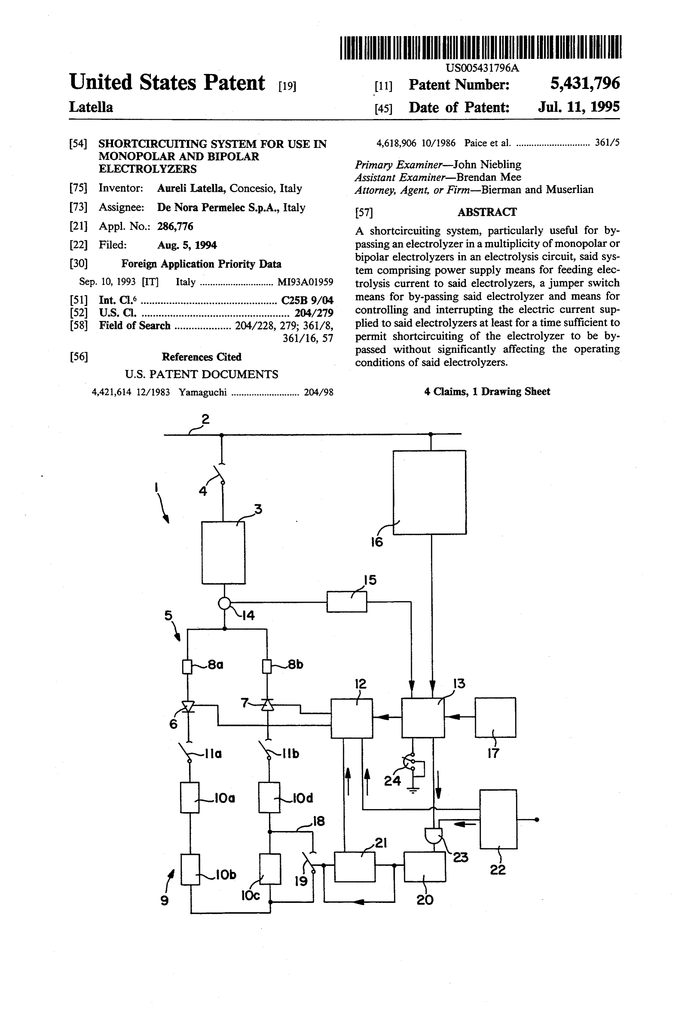
United States Patent 19 [11] Patent Number: 5431,796 Latella (45) Date of Patent: Jul. 11, 1995 54) SHORTCIRCUITING SYSTEM FOR USE IN 4,618,906 10/1986 Paice et al. ............................. 361/5
MONOPOLAR AND BIPOLAR
ELECTROLYZERS Primary Examiner-John Niebling
Assistant Examiner-Brendan Mee 75 Inventor: Aureli Latella, Concesio, Italy Attorney, Agent, or Firm-Bierman and Muserlian 73) Assignee: De Nora Permelec S.p.A., Italy (57) ABSTRACT 21 Appl. No.: 286,776 A shortcircuiting system, particularly useful for by (22 Filed: Aug. 5, 1994 passing an electrolyzer in a multiplicity of monopolar or (30) Foreign Application Priority Data bipolar electrolyzers in an electrolysis circuit, said sys tem comprising power supply means for feeding elec
Sep. 10, 1993 IT Italy ............................. MI93A01959 trolysis current to said electrolyzers, a jumper switch (5ll Int. Cli................................................ C25B 9/04 means for by-passing said electrolyzer and means for 52 U.S.C. .................................................... 204/279 controlling and interrupting the electric current sup 58) Field of Search .................... 204/228, 279; 361/8, plied to said electrolyzers at least for a time sufficient to 361/16, 57 permit shortcircuiting of the electrolyzer to be by
passed without significantly affecting the operating conditions of said electrolyzers.
4,421,614 12/1983 Yamaguchi ........................... 204/98 4 Claims, 1 Drawing Sheet
Page 2
Drawing sheet — no readable text.
Page 3
For switches operating with currents up to 20 kA and
SHORTCIRCUITING SYSTEM FOR USE IN voltages up to 300 Volts, in addition to the arcing MONOPOLAR AND BIPOLAR ELECTROLYZERS protecting contacts, also a sacrificial fuse is provided. These jumper switches, although sufficiently wide
BACKGROUND OF THE INVENTION 5 spread, require a remarkable maintenance. The arcing As is well-known, electrochemical plants comprise a someprotecting contacts must be substituted usually every tens of opening and closing procedures, and the multiplicity of electrolyzers, each one consisting in a sacrificial plurality of elementary cells assembled in the so-called the fuse after each operation. The substitution of filter press arrangement, said elementary cells being 10 onlyarcing-protecting is extremely contacts and sacrificial fuse not expensive, but requires also the assist electrically connected either in series (bipolar electro ance of specialized maintenance lyzers) or in parallel (monopolar electrolyzers). The risk of arcing in the contacts ispersonnel. not
Further, the completely elimi electrolyzers are usually fed with a current up to 500kA nated by the above solutions. In fact, the electric cur and a maximum voltage of 10 V in the case of monopo rent lar electrolyzers, and with a current up to 20 kA and a circuitis often decreased before proceeding to the short operation. In addition, forgetting to substitute maximum voltage of 300 Volts, in the case of bipolar 15 the fuse cause serious danger during the next short-cir electrolyzers.
In standard operating conditions, when one of the cuit operation.
electrolyzers is to be serviced, the electrolysis current OBJECTS OF THE INVENTION fed to the whole plant has to be interrupted to permit It is the main object of the present invention to elimi maintenance or substitution of the electrolyzer to be nate the inconveniences of the prior art by providing for serviced.
A prolonged interruption of current to the whole a short-circuiting system suitable for monopolar and plant (electrolysis circuit) causes not only a production nection electrolyzers, bipolar and the which system permits the discon subsequent connection of said electro loss but also possible damages to the internal compo 25 lyzers in a totally safe manner without interrupting the nents of the electrolyzers due to the remarkable shifts of electrolysis process.
temperature and pressure. In addition, with a prolonged It is a further object of the present invention to pro interruption of current also auxiliary equipment of the vide plant, such as compressors, could be damaged. To avoid need for a short-circuiting system which eliminates the Such a problem, the shut down as well as start-up opera 30 nance thantechnical for the assistance and requires less mainte jumper switches of the prior art. It is tions require a substantial amount of time, as the current another object of the present invention to provide for a has to be respectively decreased or increased by small highly reliable short-circuiting system, of simplified steps. The clear consequence of this is a further loss of construction and cost-effective with respect to the production. jumper switches of the prior art. In conventional plants, this problem is overcome by 35 It is a further object of the present invention to pro resorting to a jumper switch means providing for by vide for a short-circuiting system which utilizes also passing the electrolyzer to be serviced in the electrical low cost jumper switches or, in the case high cost circuit of the multiplicity of electrolyzers. To avoid jumper switches are used, to prolong indefinitely the interruption of the electrolysis process in the remaining firing of the contacts.
electrolyzers, the by-pass (disconnection) and the con The above objects, and other objects of the invention nection of the electrolyzer, once serviced, takes place which will become evident from the following descrip under electric current load. tion, are achieved by the short-circuiting system of the The electrolyzer to be serviced may by-passed by invention for use in an electrolysis circuit comprising a utilizing copper bus-bars which are connected to the multiplicity of electrolyzers, said system comprising terminal contacts of the electrolyzer. As the current 45 power supply means and means for interrupting current travelling across the plant is extremely high, the opera for a very limited period of time which does not affect tion of connecting the bus-bars involves severe dangers. the operating conditions and nevertheless allows for To overcome this problem, the short-circuiting bus short-circuiting of at least one electrolyzer out of said bars are provided with stationary contacts as well as multiplicity of electrolyzers in the electrolysis circuit. mobile contacts, sliding over the stationary ones, which 50 The characteristics and advantages of the present permits a full and safe operation. Further, the mobile invention will be illustrated in detail in the following contacts offer other advantages over the stationary description of the preferred embodiments of the present ones, that is stability in the presence of vibrations, com invention. It is however to be understood that other plete absorption of the thermal expansions, single embodiments of the short-circuiting system for mono contact series resistance. 55 polar and bipolar electrolyzers are also possible without The contact pressure is ensured by suitable springs, departing from the spirit of the present invention. one for each mobile contact. This arrangement of bus The shortcircuiting system of the invention is a short bars, fixed and mobile contacts, is provided by those circuiting system for by-passing at least one electrolyzer equipments, known in the technical field as jumper (10c) in a multiplicity of monopolar or bipolar electro switches. lyzers in an electrolysis circuit comprising power sup However, due to the high operating current, also ply means including an electric current line (2), a recti onto the mobile contacts arcing may take place during fier (5) based on thyristors (6) and (7) and a transformer short-circuiting of the electrolyzers. (3) for feeding electrolysis current to said electrolyzers This problem is overcome by suitable arcing-protect and a control system (12) connected to an automatic ing contacts which provide for anticipated closing and 65 current controller (13) connected in turn to a synchro deferred opening with respect to the main contacts, nism and measurement circuit (16), a jumper switch (18) either mobile or stationary, in order to avoid any arcing with a switch (19) for by-passing said electrolyzer (10c), to the latter. characterized in that switch (19) comprises a selector
Page 4
means (22) suitable for sending a start-up signal both to inlet of which is provided also with a signal of zero-cur the control circuit (12) and to AND gate (23), con rent of rectifier 5 from controller 13. The output signal nected in turn to said controller (13), a command circuit of gate 13 is sent to a command circuit 20. A jumper (20) connected to said gate (23) and to said jumper switch means 18 provided with switch 19 is applied at switch means (18) for the interruption of the electric the terminals of the electrolyzer to be disconnected 10c. current supplied to said electrolysis circuit for at least at The switch 19 and the command circuit 20 are con time sufficient to permit shortcircuiting of said electro nected to a limit switch 21, which senses the exact posi lyzer (10c) and a limit switch (21) to re-start said electric tion of switch 19 and makes control circuit 12 send a firing pulse to the thyristors, depending on the position current, said interruption of electric current not affect ing the operating conditions of said multiplicity of 10 of switch 19.
monopolar or bipolar electrolyzers. The operation of the system of the present invention BRIEF DESCRIPTION OF THE DRAWINGS may be summarized as follows. During normal operation of the electrolysis plant, a
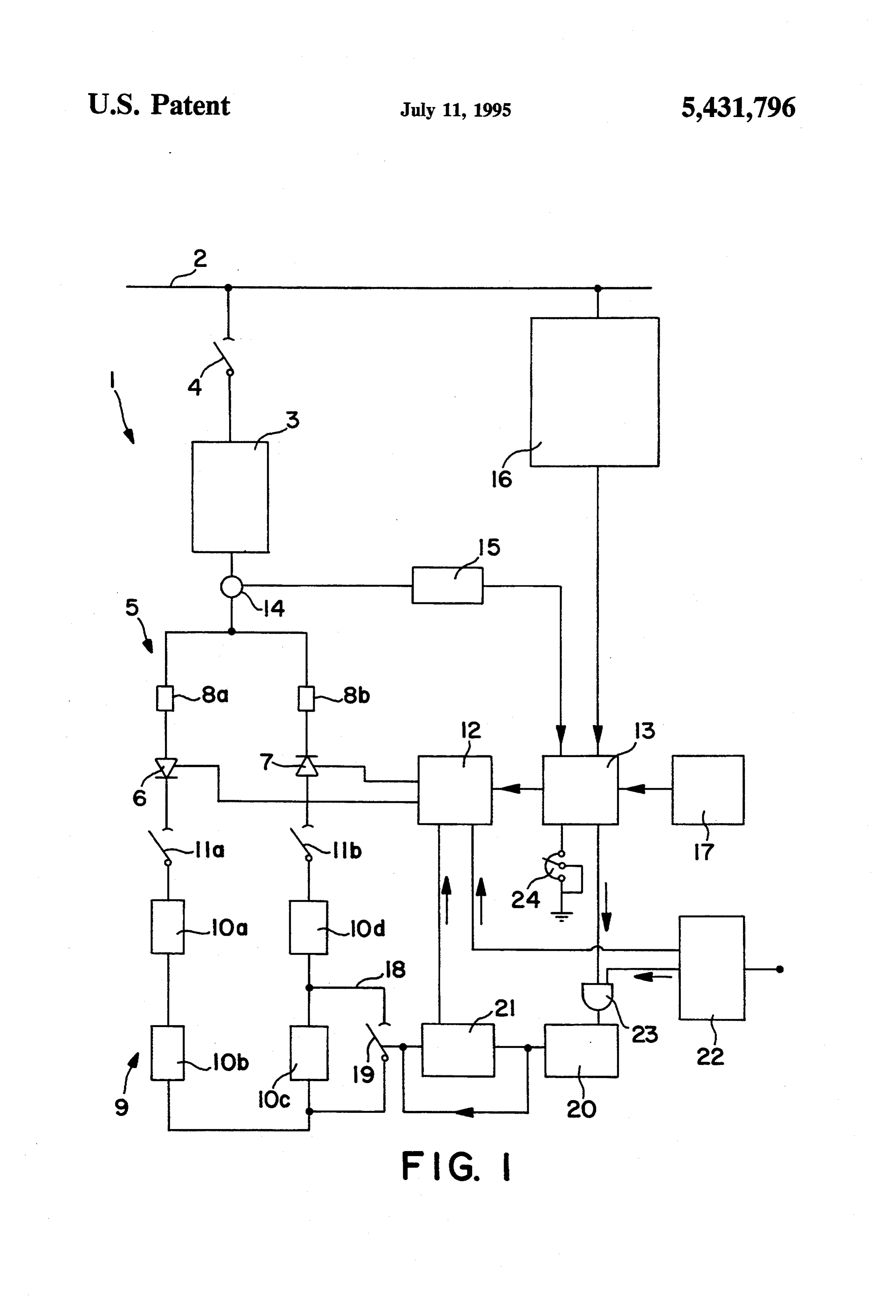
FIG. 1 is a schematic scheme of a short-circuiting primary three-phase current in the order of 11 kV flows system of the invention. 15 through line 2 at a frequency of 50 Hz. The high voltage DESCRIPTION OF THE INVENTION switch gear 4 of transformer 3 is obviously closed and the primary voltage is transformed into the output volt
The invention will be now described making refer age which is sent to the terminals of rectifier 5, that is to ence to the figure which represents an electrical block the terminals of thyristors 6 and 7. The start-up of thy diagram wherein reference numeral 1 indicates the 20 ristors 6 and 7 is controlled by the control circuit 12, short-circuiting system comprising the primary three which in turn is controlled by the automatic current phase electric current feed line 2 of the electrolysis controller 13.
plant. Line 2 is connected to a transformer 3 with a high The controller 13 receives the set point signal voltage switch gear 4. The primary of transformer 3 is through the potentiometer 24 having a positive polarity of the star-type connection, while the secondary is of 25 and a feed-back signal which is a function of the flowing the open-triangle-type connection. The electric circuit current sensed by transformer 14. It is this difference of the secondary is completed by rectifier 5 provided between the two signals that controls thyristors 6 and 7 with semi-conductors, in particular thyristors. through circuits 12 and 13. The control circuit 12 is The rectifier 5 is organized according to a Graetz synchronized by the primary voltage of line 2 by means bridge scheme and is indicated in a simplified form of 30 of synchronism and measurement circuit 16, through thyristors 6 and 7. Each thyristor 6 and 7 is provided controller 13. Therefore, firing of the thyristors 6 and 7 with a protection fuse 8a and 8b respectively. Trans takes place in phase-coincidence with transformer 3. former 3 and the rectifier 5 represent the AC/DC con Further, the signal coming from the synchronism and version unit. The output of rectifier 5, that is the termi measurement circuit 16 is used to measure the primary nals of thyristors 6 and 7 not connected to transformer 35 voltage and controlling the minimum voltage and phase 3, are connected to the electrolysis circuit comprising sequence on the primary side of the transformer 3. If electrolyzers 10a–10a connected in series. Two D.C. this voltage either decreases to 80% of the nominal isolators 11a and 1lb are positioned at the terminals of value or has a wrong sequence, the rectifier 5 is cut-out the electrolysis circuit 9 for isolating said electrolysis for protection purposes.
circuit from the power supply means consisting in elec In case one of the electrolyzers is to be by-passed, the tric current line 2, transformer 3 and rectifier 5. operator initiates the sequence by turning on selector 22 The gates of thyristors 6 and 7 of rectifier 5 are con which sends a start-up signal to the control circuit 12 nected to a control circuit 12 which generates the firing and to AND gate 23. When this signal is received, the pulses for the thyristors. The thyristors control circuit firing pulses sent from control circuit 12 to the thy 12 receives the triggering sequence of the thyristors 45 ristors 6 and 7 are stopped.
from an automatic current controller 13. The automatic As the thyristors of rectifier 5 are no more conduct current controller 13 is further connected to a synchro ing, the current goes to zero. The condition of zero-cur nism and measurement circuit 16 which provides for rent is checked by transformer 14 and by measurement sending the synchronism signal of firing the thyristors and current feed-back circuit 15. The measurement and to controller 13. Circuit 16 derives the synchronizing 50 current feed-back circuit 15 sends a signal of zero cur signal from the primary feed line 2, to which it is con rent to AND gate 23 through controller 13. This zero nected. In addition, the synchronism and measurement current signal and the start-up signal coming from selec circuit 16 controls the minimum voltage supplied by tor 22 activate AND gate 23 which operates the com line 2 in order to cut-out the rectifier 5 in case the pri mand circuit 20.
mary voltage sinks below a pre-determined level. 55 The command circuit 20 provides for closing switch Further, controller 13 is connected to the measure 19 of the jumper switch means 18 connected to the and current feed-back circuit 15, the latter receiving an electrolyzer to be excluded. The limit switch 21 senses input signal from a current transformer 14 positioned the position of switch 19 and checks whether jumper between transformer 3 and rectifier 5. Said circuit 15 switch means 18 is closed. Once said checking is ef senses the current supplied by rectifier 5. The controller fected, the limit switch sends with a small delay a signal 13 is connected to its own power supply 17. of re-starting of the firing pulses to the thyristors to the The automatic current controller 13 is further pro control circuit 12.
vided with a potentiometer 24 for the control of the In this way the supply of electric current to the elec current set-point. trolysis circuit is interrupted only for an extremely lim The system of the present invention comprises also a 65 ited time, typically in the range of 200-1000 millisec selector 22 which allows for starting the short-circuit onds, in order not to affect the operation conditions of ing operation. The selector 22 sends a start-up signal the electrolysis process. It is evident that the interrup both to the control circuit 12 and to AND gate 23, the tion of current depends on the closing time of switch 19.
Page 5
With a quick switch the interruption time may be ex trolyzer (10c), characterized in that switch (19) com tremely reduced. In addition, the signal for re-starting prises a selector means (22) suitable for sending a start the firing pulses is sent with a small delay in order to up signal both to the control circuit (12) and to AND avoid any risk that the supply of electric current to the gate (23), connected in turn to said controller (13), a electrolysis circuit 9 be resumed before the closing of 5 command circuit (20) connected to said gate (23) and to the switch 19. said jumper switch means (18) for the interruption of In the same way the jumper switch means 18 may be the electric current supplied to said electrolysis circuit opened to connect again the serviced electrolyzer to the for at least a time sufficient to permit shortcircuiting of electrolysis circuit 9. The selector 22 sends a start-up said electrolyzer (10c) and a limit switch (21) to re-start signal to the control circuit 12 and to AND gate 23. The 10 said electric current, said interruption of electric cur firing pulses to thyristors 6 and 7 are stopped and the rent not affecting the operating conditions of said multi condition of zero-current supplied by rectifier 5 is plicity of monopolar or bipolar electrolyzers. checked by means of circuits 14 and 15. Then, AND 2. The system of claim 1 wherein the automatic cur gate 23 activates the command circuit 20, which opens rent controller (13) is further connected to a measure switch 19. The limit switch 21 senses whether switch 19 15 and current transformer (14) positioned between trans has completed the opening operation and thereafter it former (3) and rectifier (5).
sends, preferably with a small predetermined delay, the 3. A method for by-passing at least one electrolyzer re-starting signal of the firing pulses to thyristors 6 and (10c) in a multiplicity of monopolar or bipolar electro 7 to the control circuit 12. lyzers in an electrolysis circuit by utilizing the short-cir The above description is only intended to illustrate 20 cuiting system of claim 1, comprising one embodiment of the present invention. The various a. turning on selector (22) to reach the zero-current details can be substituted for technical equivalents. The condition, by stopping the firing pulses from con materials and the shapes or dimensions or the elements trol circuit (12) to thyristors (6) and (7) and sending will be chosen depending on the specific requirements, a signal to AND gate (23). without departing from the spirit of the present inven 25 b. controlling the condition of zero-current by trans tion which is only intended to be defined by the follow former (14) and by circuit (15). ing appended claims. c. sending a signal of zero-current to AND gate (23) I claim: through controller (13) and a start-up signal sent to 1. A short-circuiting system for by-passing at least command circuit (20).
one electrolyzer (10c) in a multiplicity of monopolar or 30 d. closing switch (19) through command circuit (20) bipolar electrolyzers in an electrolysis circuit compris to by-pass the electrolyzer (10c). ing power supply means including an electric current e. sensing the position of switch (19) by limit switch line (2), a rectifier (5) based on thyristors (6) and (7) and (21) and a transformer (3) for feeding electrolysis current to said f. re-starting with a small delay the firing pulses to electrolyzers and a control system (12) connected to an 35 thyristors (6) and (7) by limit switch (21). automatic current controller (13) connected in turn to a 4. The method of claim 3, characterized in that the synchronism and measurement circuit (16), a jumper small delay is in the range of 200-1000 milliseconds. switch (18) with a switch (19) for by-passing said elec k
Provenance
- Collection
- Cited prior art
- Original PDF
- patentimages.storage.googleapis.com →
- Filed
- 1994-08-05
- Pages
- 5
- Method
- pdftotext (the PDF's own text layer) + pdftoppm 300dpi page scans
- Source
- Google Patents bibliographic record
- Granted
- 1995-07-11
- Inventors
- Aureli Latella; De Nora Permelec SpA
- Transcribed from
- patentimages.storage.googleapis.com →