patent · US4318393
Porous surface solar energy receiver
9 March 1982
Page 1 — bibliographic record
United States Patent (19) 11 4,318,393 Goldstein 45) Mar. 9, 1982 54 POROUS SURFACE SOLAR ENERGY 3,908,632 9/1975 Poulsen ............................... 126/271 RECEIVER 3,924,604 12/1975 Anderson ... ... 126/438 4,006,856 2/1977 Nilsson ................................ 126/270 75 Inventor: Richard J. Goldstein, Golden Valley,
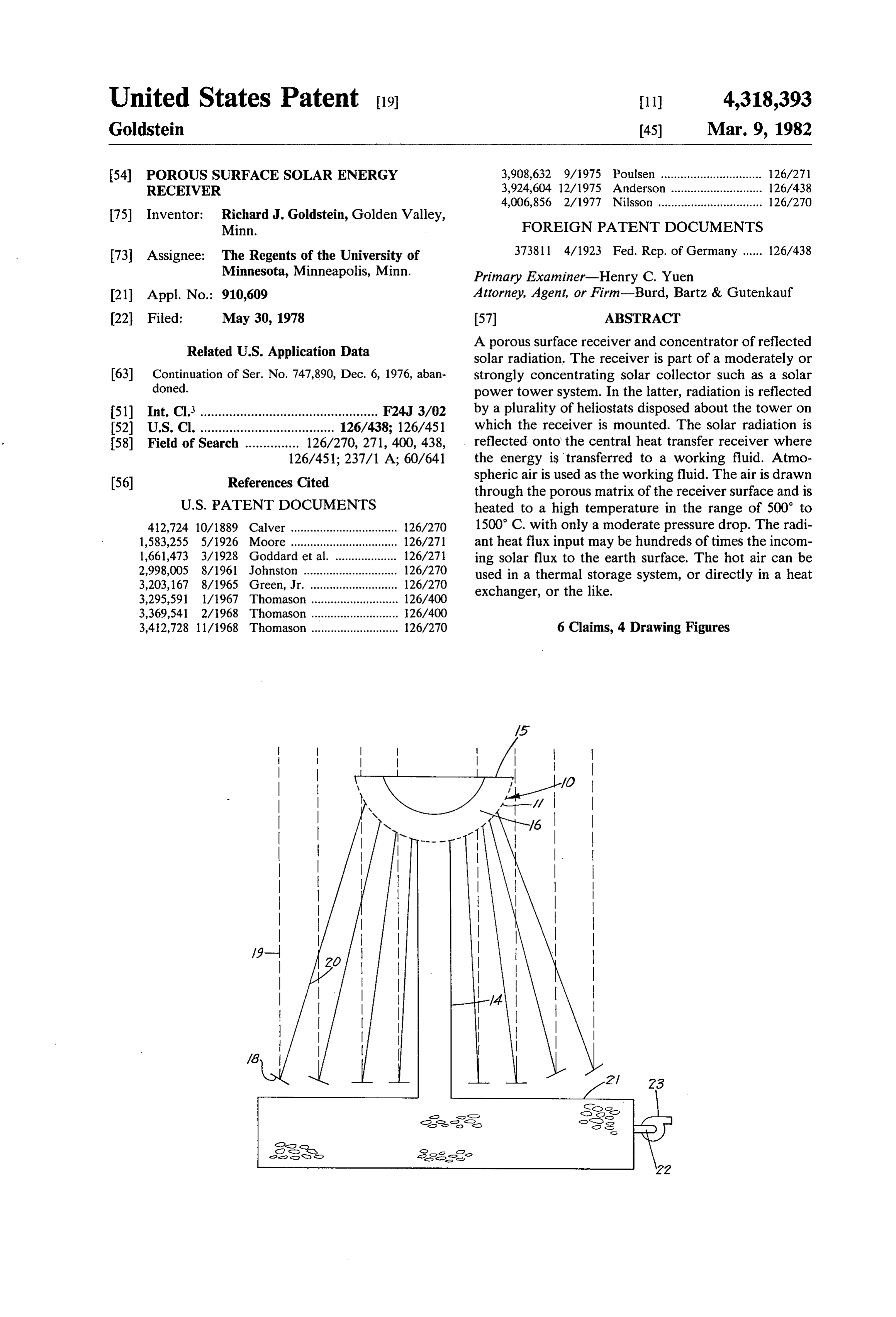
Minn. FOREIGN PATENT DOCUMENTS 73 Assignee: The Regents of the University of 373811 4/1923 Fed. Rep. of Germany ...... 126/438 Minnesota, Minneapolis, Minn. Primary Examiner-Henry C. Yuen 21 Appl. No.: 910,609 Attorney, Agent, or Firm-Burd, Bartz & Gutenkauf 22 Filed: May 30, 1978 57 ABSTRACT Related U.S. Application Data A porous surface receiver and concentrator of reflected solar radiation. The receiver is part of a moderately or 63 Continuation of Ser. No. 747,890, Dec. 6, 1976, aban strongly concentrating solar collector such as a solar doned. power tower system. In the latter, radiation is reflected 51) Int. Cl. ................................................. F24J 3/02 by a plurality of heliostats disposed about the tower on 52 U.S. Cl. ..................................... 126/438: 126/451 which the receiver is mounted. The solar radiation is 58) Field of Search ............... 126/270, 271, 400, 438, reflected onto the central heat transfer receiver where 126/451; 237/1 A; 60/641 the energy is transferred to a working fluid. Atmo 56) References Cited spheric air is used as the working fluid. The air is drawn through the porous matrix of the receiver surface and is
412,724 10/1889 Calver ................................. 126/270 1500 C. with only a moderate pressure drop. The radi 1,583,255 5/1926 Moore.......... ... 126/271 antheat flux input may be hundreds of times the incom 1,661,473 3/1928 Goddard et al. ... 126/271 ing solar flux to the earth surface. The hot air can be 2,998,005 8/1961 Johnston ......... ... 126/270 used in a thermal storage system, or directly in a heat 3,203,167 8/1965 Green, Jr. .... ... 126/270 exchanger, or the like.
3,295,591 1/1967 Thomason ........................... 126/400
3,412,728 1/968 Thomason ........................... 26/270 6 Claims, 4 Drawing Figures
Page 2
Drawing sheet — no readable text.
Page 3
Drawing sheet — no readable text.
Page 4
the collector panel, essentially no concentration occurs
POROUS SURFACE SOLAR ENERGY RECEIVER and the system could not be used at high temperature. Thomason U.S. Pat. No. 3,412,728 shows a solar
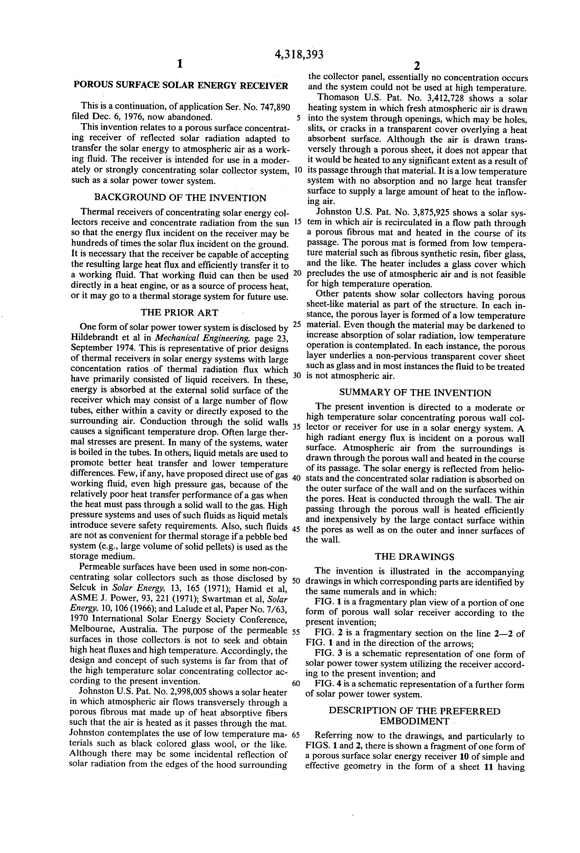
This is a continuation, of application Ser. No. 747,890 heating system in which fresh atmospheric air is drawn filed Dec. 6, 1976, now abandoned. into the system through openings, which may be holes, This invention relates to a porous surface concentrat slits, or cracks in a transparent cover overlying a heat ing receiver of reflected solar radiation adapted to absorbent surface. Although the air is drawn trans transfer the solar energy to atmospheric air as a work versely through a porous sheet, it does not appear that ing fluid. The receiver is intended for use in a moder it would be heated to any significant extent as a result of ately or strongly concentrating solar collector system, 10 its passage through that material. It is a low temperature such as a solar power tower system. system with no absorption and no large heat transfer BACKGROUND OF THE INVENTION surface to supply a large amount of heat to the inflow ing air.
Thermal receivers of concentrating solar energy col Johnston U.S. Pat. No. 3,875,925 shows a solar sys lectors receive and concentrate radiation from the sun 15 tem in which air is recirculated in a flow path through so that the energy flux incident on the receiver may be a porous fibrous mat and heated in the course of its hundreds of times the solar flux incident on the ground. passage. The porous mat is formed from low tempera It is necessary that the receiver be capable of accepting ture material such as fibrous synthetic resin, fiberglass, the resulting large heat flux and efficiently transfer it to 20 and the like. The heater includes a glass cover which a working fluid. That working fluid can then be used precludes the use of atmospheric air and is not feasible directly in a heat engine, or as a source of process heat, for high temperature operation.
or it may go to a thermal storage system for future use. Other patents show solar collectors having porous
THE PRIOR ART
sheet-like material as part of the structure. In each in stance, the porous layer is formed of a low temperature
One form of solar power tower system is disclosed by 25 material. Even though the material may be darkened to Hildebrandt et al in Mechanical Engineering, page 23, increase absorption of solar radiation, low temperature September 1974. This is representative of prior designs operation is contemplated. In each instance, the porous of thermal receivers in solar energy systems with large layer underlies a non-pervious transparent cover sheet concentation ratios of thermal radiation flux which such as glass and in most instances the fluid to be treated 30 is not atmospheric air.
have primarily consisted of liquid receivers. In these, energy is absorbed at the external solid surface of the SUMMARY OF THE INVENTION receiver which may consist of a large number of flow
The tubes, either within a cavity or directly exposed to the high temperature present invention is directed to a moderate or surrounding air. Conduction through the solid walls 35 lector or receiver solar concentrating porous wall col causes a significant temperature drop. Often large ther high radiant energy flux isinincident for use a solar energy system. A mal stresses are present. In many of the systems, water surface. Atmospheric air from theonsurroundings a porous wall
is boiled in the tubes. In others, liquid metals are used to drawn through the porous wall and heated in the course promote better heat transfer and lower temperature of its passage. The solar energy is reflected from helio differences. Few, if any, have proposed direct use of gas 40 stats and the concentrated solar radiation is absorbed on working fluid, even high pressure gas, because of the the outer relatively poor heat transfer performance of a gas when the pores.surface Heat is of the wall and on the surfaces within conducted through the wall. The air the heat must pass through a solid wall to the gas. High passing through the pressure systems and uses of such fluids as liquid metals and inexpensively by porous wall is heated efficiently introduce severe safety requirements. Also, such fluids 45 the pores as well as on the outercontact the large and surface within inner surfaces of are not as convenient for thermal storage if a pebble bed the wall.
system (e.g., large volume of solid pellets) is used as the storage medium. THE DRAWINGS Permeable surfaces have been used in some non-con The invention is illustrated in the accompanying centrating solar collectors such as those disclosed by 50 drawings in which corresponding parts are identified by Selcuk in Solar Energy, 13, 165 (1971); Hamid et al, the same numerals and in which:
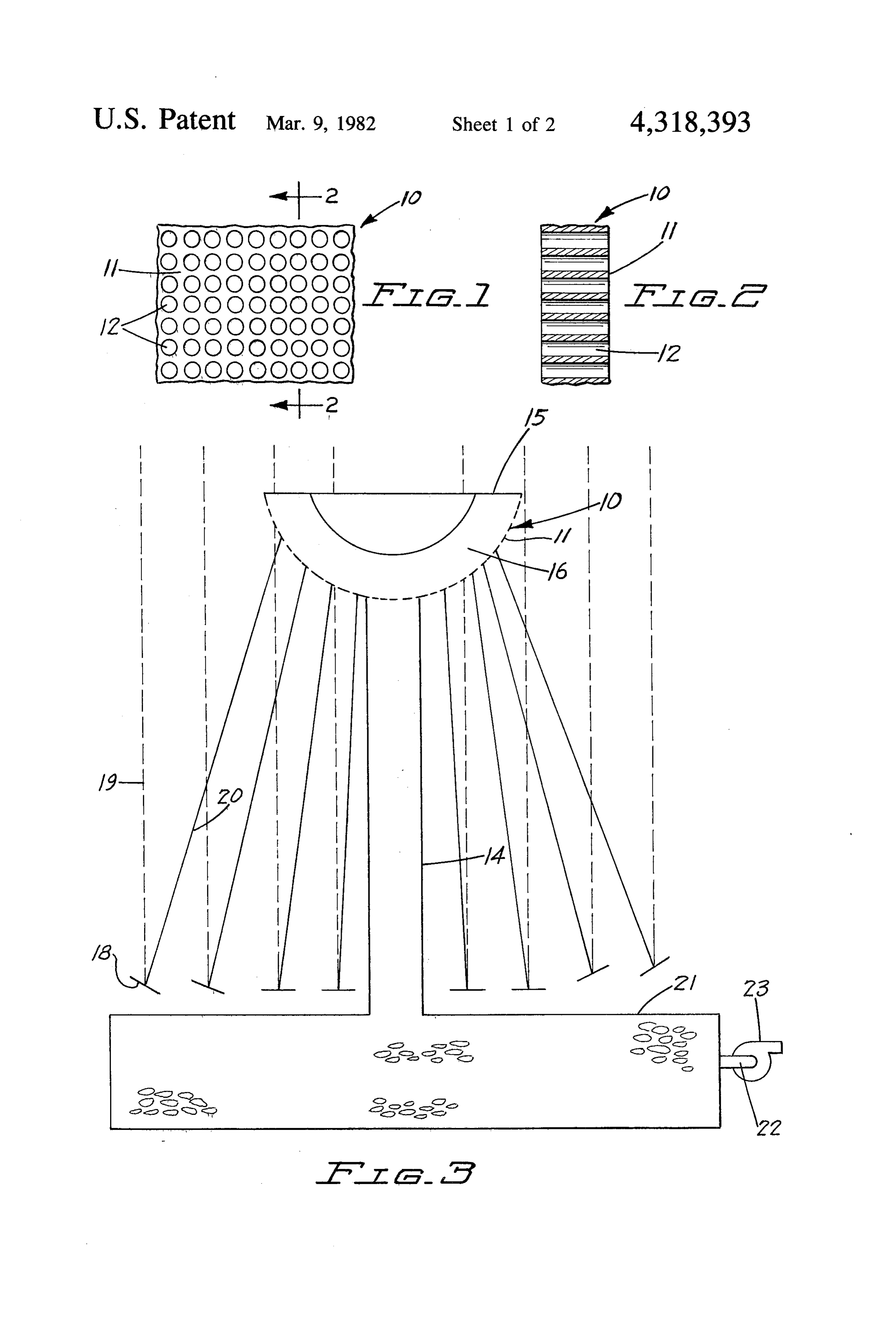
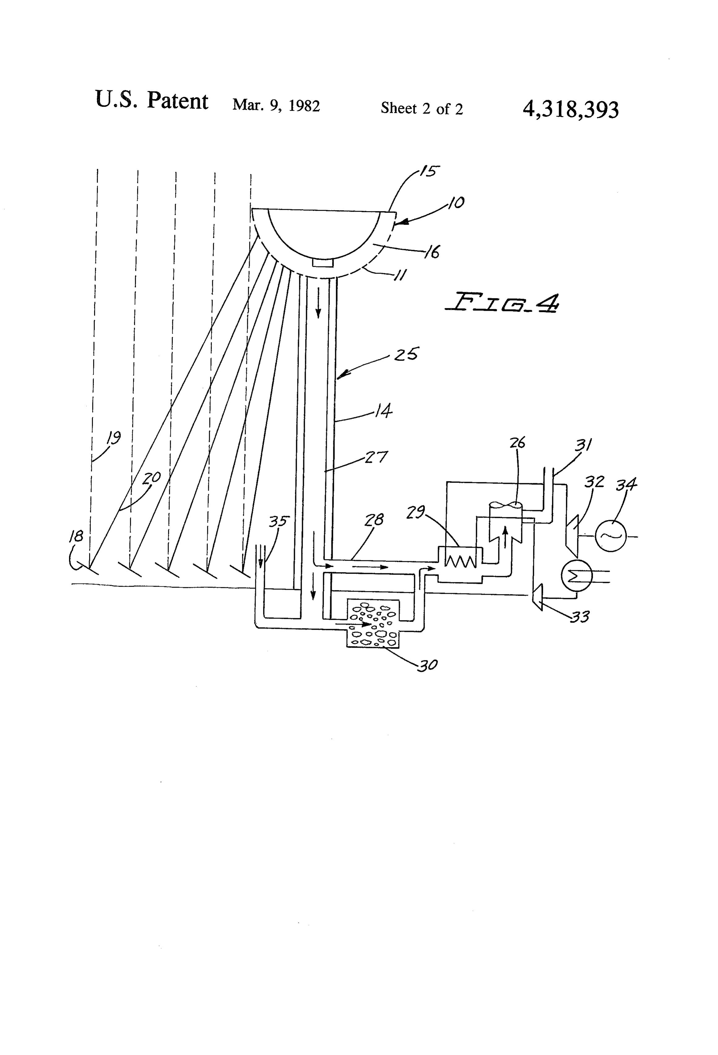
ASME J. Power, 93,221 (1971); Swartman et al, Solar FIG. 1 is a fragmentary plan view of a portion of one Energy, 10,106 (1966); and Lalude et al, Paper No. 7/63, form 1970 International Solar Energy Society Conference, presentofinvention; porous wall solar receiver according to the Melbourne, Australia. The purpose of the permeable 55 FIG. 2 is a fragmentary section on the line 2-2 of surfaces in those collectors is not to seek and obtain high heat fluxes and high temperature. Accordingly, the FIG. 1 and in the direction of the arrows; FIG. 3 is a schematic representation of one form of design and concept of such systems is far from that of solar power tower system utilizing the receiver accord the high temperature solar concentrating collector ac ing to the present invention; and cording to the present invention. 60 FIG. 4 is a schematic representation of a further form Johnston U.S. Pat. No. 2,998,005 shows a solar heater of solar power tower system.
in which atmospheric air flows transversely through a porous fibrous mat made up of heat absorptive fibers DESCRIPTION OF THE PREFERRED such that the air is heated as it passes through the mat. EMBODIMENT . Johnston contemplates the use of low temperature ma 65 Referring now to the drawings, and particularly to terials such as black colored glass wool, or the like. FIGS. 1 and 2, there is shown a fragment of one form of Although there may be some incidental reflection of a porous surface solar energy receiver 10 of simple and solar radiation from the edges of the hood surrounding effective geometry in the form of a sheet 11 having
Page 5
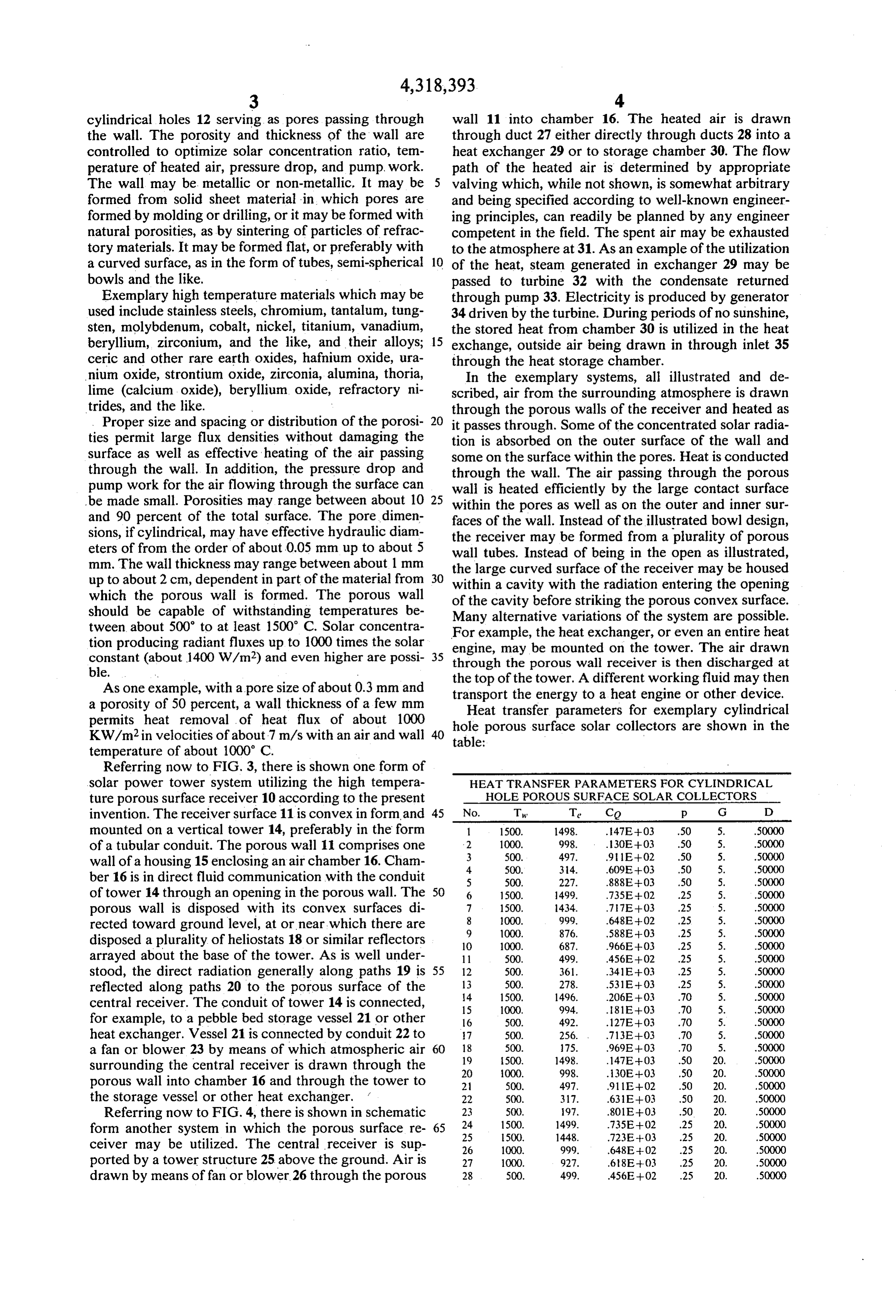
cylindrical holes 12 serving as pores passing through wall 11 into chamber 16. The heated air is drawn the wall. The porosity and thickness of the wall are through duct 27 either directly through ducts 28 into a controlled to optimize solar concentration ratio, tem heat exchanger 29 or to storage chamber 30. The flow perature of heated air, pressure drop, and pump, work. path of the heated air is determined by appropriate The wall may be metallic or non-metallic. It may be valving which, while not shown, is somewhat arbitrary formed from solid sheet material in which pores are and being specified according to well-known engineer formed by molding or drilling, or it may be formed with ing principles, can readily be planned by any engineer natural porosities, as by sintering of particles of refrac competent in the field. The spent air may be exhausted tory materials. It may be formed flat, or preferably with to the atmosphere at 31. As an example of the utilization a curved surface, as in the form of tubes, semi-spherical 10 of the heat, steam generated in exchanger 29 may be bowls and the like. passed to turbine 32 with the condensate returned Exemplary high temperature materials which may be through pump 33. Electricity is produced by generator used include stainless steels, chromium, tantalum, tung 34 driven by the turbine. During periods of no sunshine, sten, molybdenum, cobalt, nickel, titanium, vanadium, the stored heat from chamber 30 is utilized in the heat beryllium, zirconium, and the like, and their alloys; 15 exchange, outside air being drawn in through inlet 35 ceric and other rare earth oxides, hafnium oxide, ura through the heat storage chamber. nium oxide, strontium oxide, zirconia, alumina, thoria, In the exemplary systems, all illustrated and de lime (calcium oxide), beryllium oxide, refractory ni scribed, air from the surrounding atmosphere is drawn trides, and the like. through the porous walls of the receiver and heated as Proper size and spacing or distribution of the porosi it passes through. Some of the concentrated solar radia ties permit large flux densities without damaging the tion is absorbed on the outer surface of the wall and surface as well as effective heating of the air passing some on the surface within the pores. Heat is conducted through the wall. In addition, the pressure drop and through the wall. The air passing through the porous pump work for the air flowing through the surface can wall is heated efficiently by the large contact surface be made small. Porosities may range between about 10 25 within the pores as well as on the outer and inner sur and 90 percent of the total surface. The pore dimen faces of the wall. Instead of the illustrated bowl design, sions, if cylindrical, may have effective hydraulic diam the receiver may be formed from a plurality of porous eters of from the order of about 0.05 mm up to about 5 wall tubes. Instead of being in the open as illustrated, mm. The wall thickness may range between about 1 mm the large curved surface of the receiver may be housed up to about 2 cm, dependent in part of the material from 30 within a cavity with the radiation entering the opening which the porous wall is formed. The porous wall should be capable of withstanding temperatures be of the cavity before striking the porous convex surface. Many alternative variations of the system are possible.
tween about 500' to at least 1500 C. Solar concentra For example, the heat exchanger, or even an entire heat tion producing radiant fluxes up to 1000 times the solar constant (about 1400 W/m2) and even higher are possi 35 engine, through may be mounted on the tower. The air drawn the porous wall receiver is then discharged at ble.
the top of
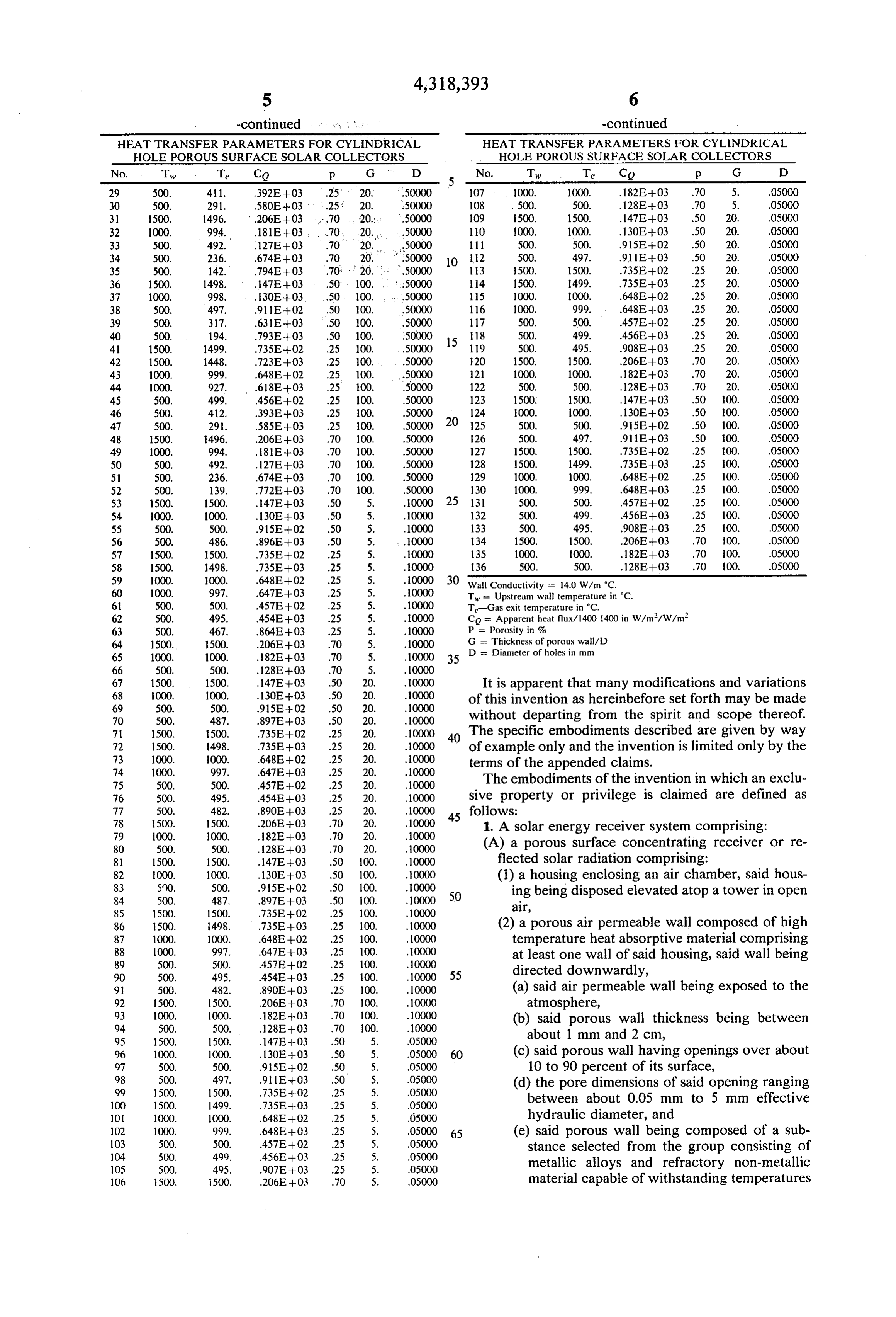
As one example, with a pore size of about 0.3 mm and transport the the tower. A different working fluid may then a porosity of 50 percent, a wall thickness of a few mm energy to a heat engine or other device. Heat transfer parameters for exemplary cylindrical permits heat removal of heat flux of about 1000 hole porous surface solar collectors are shown in the KW/m2 in velocities of about 7 m/s with an air and wall 40 table:
temperature of about 1000 C.
Referring now to FIG, 3, there is shown one form of solar power tower system utilizing the high tempera HEAT TRANSFER PARAMETERS FOR CYLINDRICAL ture porous surface receiver 10 according to the present HOLE POROUS SURFACE SOLAR COLLECTORS invention. The receiver surface 11 is convex in form, and 45 No. T Te Co p G D mounted on a vertical tower 14, preferably in the form 1 1500. 1498. .47E-O3 .50 5. 50000 of a tubular conduit. The porous wall 11 comprises one 2
wall of a housing 15 enclosing an air chamber 16. Cham 4. 500. 34. .609E-03 .50 5. 50000 ber 16 is in direct fluid communication with the conduit 5 500. 227. .888E-03 .50 5. 50000 of tower 14 through an opening in the porous wall. The 50 6 1500. 1499. .735E-02 .25 5. 50000 porous wall is disposed with its convex surfaces di 7
OOO.
rected toward ground level, at or near which there are 9 1000. 876. 588E--O3 .25 5. 50000 disposed a plurality of heliostats 18 or similar reflectors O 1000. 687. 966E-O3 .25 5. 50000 arrayed about the base of the tower. As is well under 11 500. 499. 456E-02 .25 5. 50000 stood, the direct radiation generally along paths 19 is 55 12 500. 361. 341E03 .25 5. 50000 reflected along paths 20 to the porous surface of the 13
central receiver. The conduit of tower 14 is connected, 15 1000. 994. 81E-O3 .70 5. 50000 for example, to a pebble bed storage vessel 21 or other 16 500. 492. 127E-03 .70 5. 50000 heat exchanger. Vessel 21 is connected by conduit 22 to 7 500. 256. . .713E--O3 .70 5. 50000 a fan or blower 23 by means of which atmospheric air 60 18
surrounding the central receiver is drawn through the 20 000. 998. 3OE-03 .50 20. 50000 porous wall into chamber 16 and through the tower to 21 500. 497, 911E-02 .50 20. 50000 the storage vessel or other heat exchanger. 22 500. 3.17. .63E-03 .50 20. 50000 Referring now to FIG. 4, there is shown in schematic 23
form another system in which the porous surface re 65 25 500. 1448. 723E--O3 .25 20. 50000 ceiver may be utilized. The central receiver is sup 26 1000. 999. .648E--02 .25 20. 50000 ported by a tower structure 25 above the ground. Air is 27 1000. 927. .68E-03 .25 20. 50000 drawn by means of fan or blower 26 through the porous 28 500. 499. 456E-02 .25 20. 50000
Page 6
-continued y 8, , . " -continued
HEAT TRANSFER PARAMETERS FOR CYLINERICAL HEAT TRANSFER PARAMETERS FOR CYLINEORICAL HOLE POROUS SURFACE SOLAR COLLECTORS HOLE POROUS SURFACE SOLAR COLLECTORS No. Tw Te Co p G D 5 - No. Tw Te Co p G D 29 500, 41, .392E+03 .25' 20, .50000 107 1000. 1000. .182E--03 .70 5. 05000 30 500, 291. .580E--03 .25: 20. 50000 08 500. 500. 128E-03 .70 5. .05000 31 1500. 1496. .206E--03 ....70 20. .50000 109 1500. 1500. .147E--O3 .50 20. .05000 32 1000. 994, 181E+03, 70. 20. 50000 110 1000, 1000. 130E-03 .50 20. 05000 33 500. 492. .127E +03 .70 20, 50000 11 500. 500. 915E-02 .50 20. 05000 34 500. 236. 674E-03 .70 20, 50000 10 12 500. 497. 911E-03 .50 20, .05000 35 500. 142. .794E--03 .70. 20. . .50000 13 500, 1500. 735E-02 .25 20. .05000 36 1500. 1498. .47E-03 .50. 100. ... : :50000 14 1500. 1499. .735E-03 .25 20. .05000 37 000. 998. , 130E+03 .50, 100. . . .50000 15 000. 1000. 648E-02 .25 20. .05000 38 500, 497. 911E--02 .50 100. 50000 116 1000. 999. . .648E--O3 25 20. 05000 39 500. 317. .631E--03 .50 100. 50000 117 500, 500. 457E-02 .25 20. 05000 40 500, 194. .793E--O3 .50 100. 50000 15 is 500. 499. 456E--03 .25 20, .05000 4. 1500. 1499. .735E-02 .25 100. 50000 19 500. 495. .908E--03 .25 20, .05000 42 1500. 1448. .723E--03 .25 100. . . .50000 20 1500. 1500. .206E--03 .70 20. 05000 43 1000. 999. .648E--02 .25 100. .50000 21 1000. 1000. .182E--O3 .70 20. 05000 44 1000. 927. .618E--03 .25 100. 50000 122 500. 500. 128E--O3 .70 20. 05000 45 500. 499. 456E--02 .25 100. 50000 123 1500. 1500. .147E-03 .50 100. 05000 46 500. 412. .393E-03 .25 100. 50000 124 000. 1000. .130E-03 .50 00. 05000 47 500. 29. 585E-03 .25 100. 50000 20 125 500. 500. 915E-02 .50 100. .05000 48 500. 496, .206E-03 .70 100. 50000 26 500. 497. 911E-03 .50 00. 05000 49 1000. 994. 8E-03 .70 100. 50000 127 1500. 1500. 735E-02 .25 100. 05000 50 500, 492. .127E-03 .70 100. 50000 128 1500. 1499. 735E-03 .25 00. 05000 51 500. 236. 674E-03 .70 100. 50000 129 1000. 1000. 648E--02 .25 100. 05000 52 500. 139. .772E--03 .70 100. 50000 130 1000. 999, 648E-03 .25 100. .05000 53 1500. 500. .47E-03 .50 5. 0000 25 131 500. 500. 457E-02 .25 100. 05000 54 1000. 1000. .130E-03 .50 5. 10000 132 500. 499. 456E-03 .25 100. .05000 55 500. 500. 915E--02 .50 5. 10000 133 500. 495. .908E-03 .25 100. 05000 56 500. 486. .896E--O3 .50 5. 10000 134 1500, 1500. .206E-03 .70 100. 05000 57 1500. 1500. .735E-02 .25 5. 10000 135 1000. 1000. .182E--03 .70 100. .05000 58 500. 1498. .735E--O3 .25 5. 10000 136 500. 500. .128E--03 .70 100. .05000 59 1000. 1000. .648E--02 .25 5. 0000 30 Wall Conductivity = 14.0 W/m C.
60 1000. 997. 647E-03 .25 5. ..10000 T = Upstream wall temperature in C.
6 500. 500, .457E-02 .25 5. 10000 T-Gas exit temperature in C.
62 500. 495. 454E-03 .25 5. 0000 Co = Apparent heat flux/1400 1400 in w/m/W/m2 63 500. 467. .864E-03 .25 5. 10000 P = Porosity in % 64 1500. 500. .206E-03 .70 5. 10000 G = Thickness of porous wall/D 65 1000, 1000, 182E+03 .70 5. 10000 35 D are diameter of holes in mm 66 500, 500. 128E-03 .70 5. 10000 67 1500. 1500. .147E--03 .50 20. 10000 It is apparent that many modifications and variations 68 1000. 1000. .130E--03 .50 20, 10000 of this invention as hereinbefore set forth may be made 69 500. 500. 915E-02 .50 20. 10000 70 500. 487. .897E--03 .50 20. 10000 without departing from the spirit and scope thereof. 71 1500, 500. .735E-02 .25 20. 10000 40 The specific embodiments described are given by way 72 1500. 1498. .735E-03 .25 20. 0000 of example only and the invention is limited only by the 73 1000. 1000. .648E--02 .25 20. 10000 terms of the appended claims.
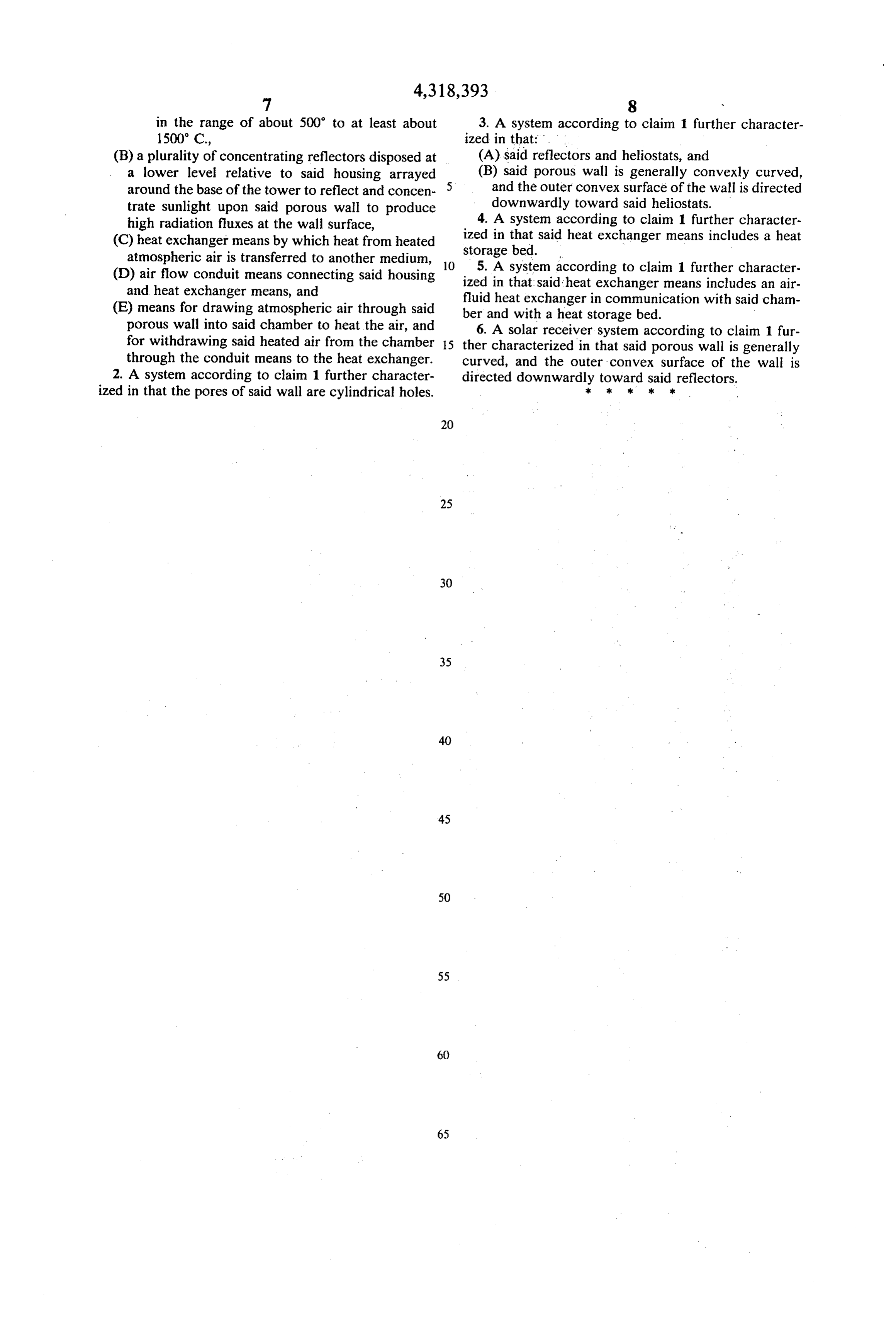
74 1000. 997. .647E--03 .25 20. ..10000 75 500, 500. 457E--02 .25 20. 10000 The embodiments of the invention in which an exclu 76 500. 495. 454E-03 .25 20. 10000 sive property or privilege is claimed are defined as 77 500. 482. .890E-03 .25 20. 10000 45 follows:
1. A solar energy receiver system comprising:
80 500, 500, .128E-03 .70 20. 10000 (A) a porous surface concentrating receiver or re 81 1500. 1500. .147E-03 .50 100, 10000 flected solar radiation comprising: 82 000. 1000. 130E-03 .50 100. 0000 (1) a housing enclosing an air chamber, said hous
50 ing being disposed elevated atop a tower in open 85 1500. 1500. .735E-02 .25 100. 10000 alr, 86 500, 498. .735E-03 .25 100. 0000 (2) a porous air permeable wall composed of high 87 1000. 1000. .648E--02 .25 100. 10000 temperature heat absorptive material comprising
at least one wall of said housing, said wall being 90 500. 495. 454E-O3 .25 100. 10000 55 directed downwardly, 9. 500, 482. .890E-03 .25 100. 10000 (a) said air permeable wall being exposed to the 92 1500. 1500. 206E-03 70 100, 10000 atmosphere,
(b) said porous wall thickness being between 95 500. 1500. 147E--O3 .50 5, 05000 about 1 mm and 2 cm, 96 1000. 1000. 13OE-03 .50 5. 05000 60 (c) said porous wall having openings over about 97 500. 500. 95E-02 .50 5. 05000 10 to 90 percent of its surface, 98 500. 497. 91 IE+03 .50 5. 05000 (d) the pore dimensions of said opening ranging 99 1500. 1500. .735E-02 .25 5. 05000 100 1500, 1499. .735E--03 .25 5. 05000 between about 0.05 mm to 5 mm effective 101 1000. 1000, .648E--02 .25 5. 05000 hydraulic diameter, and 102 1000. 999. .648E-03 25 5. 05000 65 (e) said porous wall being composed of a sub
stance selected from the group consisting of 105 500, 495, .907E-03 .25 5. 05000 metallic alloys and refractory non-metallic 106 500, 500. .206E-03 70 5. 05.000 material capable of withstanding temperatures
Page 7
in the range of about 500 to at least about 3. A system according to claim 1 further character 1500° C., ized in that: . .
(B) a plurality of concentrating reflectors disposed at (A) said reflectors and heliostats, and a lower level relative to said housing arrayed (B) said porous wall is generally convexly curved, around the base of the tower to reflect and concen 5. and the outer convex surface of the wall is directed trate sunlight upon said porous wall to produce downwardly toward said heliostats. high radiation fluxes at the wall surface, 4. A system according to claim 1 further character (C) heat exchanger means by which heat from heated ized in that said heat exchanger means includes a heat storage bed.
atmospheric air is transferred to another medium, 10 5. A system
(D) air flow conduit means connecting said housing ized in that saidaccording heat to claim 1 further character exchanger means includes an air and heat exchanger means, and fluid heat exchanger in communication with said cham (E) means for drawing atmospheric air through said ber and with a heat storage bed. porous wall into said chamber to heat the air, and 6. A solar receiver system according to claim 1 fur for withdrawing said heated air from the chamber 15 ther characterized in that said porous wall is generally through the conduit means to the heat exchanger. curved, and the outer convex surface of the wall is 2. A system according to claim 1 further character directed downwardly toward said reflectors. ized in that the pores of said wall are cylindrical holes. ck :k k k k
Page 8
UNITED STATES PATENT AND TRADEMARK OFFICE
CERTIFICATE OF CORRECTION
INVENTOR(S) : Richard J. Goldstein
It is certified that error appears in the above-identified patent and that said Letters Patent are hereby corrected as shown below:
Column 1, 1ine 29, "concentation" should be --concentration--.
Column 6. 1ine 33, "1400" (2nd occurrence) should be omitted.
line 3, "and" (1st occurrence) should be --are--. signed and sealed this
First Day of February 1983
SEAL
Attest:
GERALDJ. MOSSINGHOFF
Attesting Officer Commissioner of Patents and Trademarks
Provenance
- Collection
- Cited prior art
- Original PDF
- patentimages.storage.googleapis.com →
- Filed
- 1978-05-30
- Pages
- 8
- Method
- pdftotext (the PDF's own text layer) + pdftoppm 300dpi page scans
- Source
- Google Patents bibliographic record
- Granted
- 1982-03-09
- Inventors
- Richard J. Goldstein; University of Minnesota System
- Transcribed from
- patentimages.storage.googleapis.com →