patent · US4306613
Passive cooling system
22 December 1981
Page 1 — bibliographic record
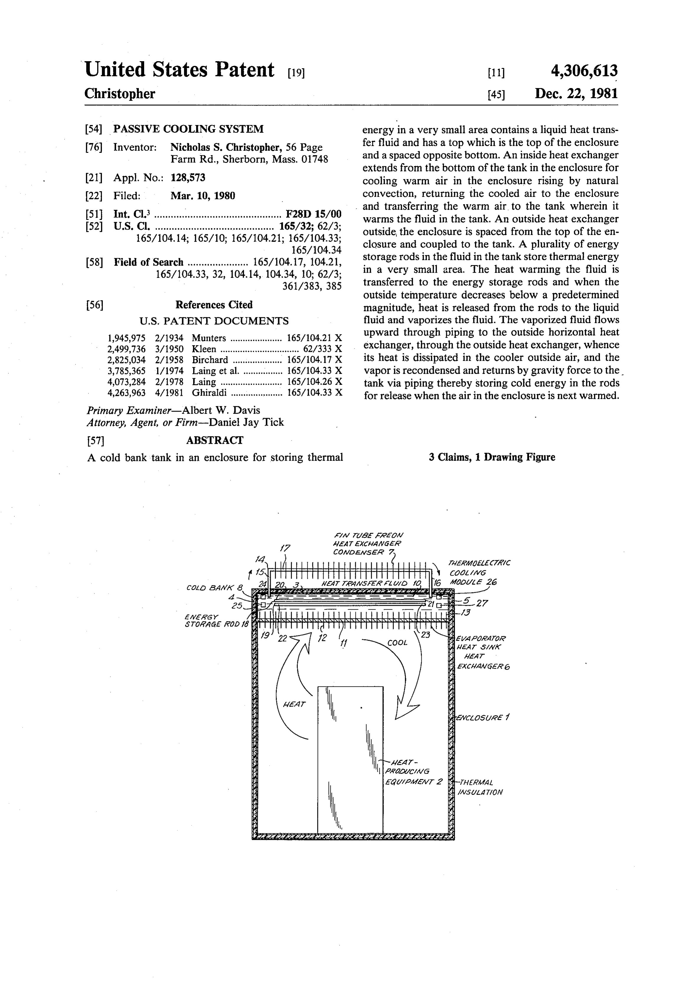
United States Patent (19) 11) 4,306,613 Christopher 45) Dec. 22, 1981 54 PASSIVE COOLING SYSTEM energy in a very small area contains a liquid heat trans 76 Inventor: Nicholas S. Christopher, 56 Page fer fluid and has a top which is the top of the enclosure Farm Rd., Sherborn, Mass. 0.1748 and a spaced opposite bottom. An inside heat exchanger extends from the bottom of the tank in the enclosure for 21 Appl. No.: 128,573 cooling warm air in the enclosure rising by natural 22 Filed: Mar. 10, 1980 convection, returning the cooled air to the enclosure 51 Int. Cl.3 ........... ........................ F28D 15/00 and transferring the warm air to the tank wherein it warms the fluid in the tank. An outside heat exchanger 52 U.S. Cl. ........................................... 165/32; 62/3; outside, the enclosure is spaced from the top of the en 165/104.14; 165/10; 165/104.21; 165/104.33; closure and coupled to the tank. A plurality of energy
58 Field of Search ...................... 165/104.17, 104.21, storage rods in the fluid in the tank store thermal energy 165/104.33, 32, 104.14, 104.34, 10; 62/3; in a very small area. The heat warming the fluid is 361/383,385 transferred to the energy storage rods and when the outside temperature decreases below a predetermined 56) References Cited magnitude, heat is released from the rods to the liquid
1,945,975 2/1934 Munters ..................... 165/104.21 X upward through piping to the outside horizontal heat 2,499,736 3/1950 Kleen ................................ 62/333 X exchanger, through the outside heat exchanger, whence 2,825,034 2/1958 Birchard . ... 165/104.17X its heat is dissipated in the cooler outside air, and the 3,785,365 1/1974 Laing etal ... 165/104.33 X vapor is recondensed and returns by gravity force to the 4,073,284 2/1978 Laing ...... ... 165/104.26X tank via piping thereby storing cold energy in the rods 4,263,963 4/1981 Ghiraldi -8 ... 165/0433x for release when the air in the enclosure is next warmed. Primary Examiner-Albert W. Davis
Attorney, Agent, or Firm-Daniel Jay Tick
A cold bank tank in an enclosure for storing thermal 3 Claims, Drawing Figure
CoAvadaasaar Z.
aawaasay sassissinaissaratarassassistasianatastasiaissanars
STOAAGE AOD f6 s geAfaav
Sawa
Aaw
aaZ
Page 2
Drawing sheet — no readable text.
Page 3
tanks and large heat exchangers, as well as large vol
PASSIVE COOLING SYSTEM umes of water base solutions which are difficult to transport to remote sites.
BACKGROUND OF THE INVENTION The principal object of the invention is to provide a The present invention relates to a passive cooling passive cooling system which functions efficiently, ef. system. More particularly, the invention relates to a fectively, reliably and economically to maintain a cool solid state passive cooling system for cooling an enclo environment for enclosed heat-producing equipment. sure sheltering heat-producing equipment such as, for An object of the invention is to provide a passive example, a microwave repeater station. cooling system which functions efficiently, effectively Heat-producing equipment such as, for example, re 10 and reliably to cool enclosed heat-producing equipment mote microwave repeater stations, are frequently sub without consuming energy, except under extreme con jected to very high ambient temperatures which may ditions.
have a severe adverse affect on the life, reliability and Another object of the invention is to provide a pas performance of the equipment. Accordingly, conven sive cooling system which utilizes only solid state com tional air conditioners have been used heretofore to 15 ponents and has no moving parts.
reduce the temperature of the equipment enclosure Still another object of the invention is to provide a below the maximum specified by the equipment manu passive cooling system of considerably smaller dimen facturer. The maximum specified temperature is typi sions than known systems for cooling enclosed heat cally 104 F. or 40 C. producing equipment.
A disadvantage of conventional air conditioners, 20 Yet another object of the invention is to provide a however, is that they consume large amounts of electri passive cooling system of simple structure, which is cal energy, from 800 to 1,500 watts, which energy is inexpensive in manufacture and operation, and func produced by large engine generator sets. The power tions efficiently, effectively and reliably to maintain a required to run a conventional air conditioner is gener cool environment for enclosed heat-producing equip ally two or three times higher than the power required 25 for the equipment. Thus, considerably larger volumes ment. An object of the invention is to provide a passive of expensive fuel are consumed in producing the energy cooling system having considerably smaller dimensions than would be required with the passive cooling system and being considerably more aesthetically attractive of the invention.
Several passive cooling systems are currently being 30 than known systems for cooling enclosed heat-produc used to solve the aforedescribed problem. However, ing equipment, and being of simpler structure and less these systems utilize very large inside and outside heat expensive in manufacture than such known systems. Another object of the invention is to provide a pas exchangers as well as very large thermal storage tanks, since water or a water base solution is used as the ther sive cooling system which maintains a cooler environ mal storage medium. The water base passive system is 35 ment for enclosed heat-producing equipment than so inefficient in thermal storage and thermal transfer known Still water storage cooling systems.
another object of the invention is to provide a characteristics, operating on the thermosiphon process, that the prior art passive cooling systems are almost as passive cooling system which functions more efficiently large as the equipment enclosure itself. Furthermore, and effectively, is of smaller size and dimensions and is the passive cooling systems of the prior art are limited 40 less expensive in manufacture and operation than to desert applications, where nighttime temperatures known water base thermosiphon passive cooling sys drop sufficiently to permit the thermal storage water terms.
base solution to drop sufficiently in temperature to per An object of the invention is to provide a passive mit cooling during the following daytime period. cooling system utilizing energy storage rods for provid Passive cooling systems are described in a paper enti 45 ing a great amount of cold storage in a small, compact tled "Standard Long-Range Operating Stations in Shel volume.
ters With Integrated Thermal-Syphon System” by Another object of the invention is to provide a pas Franz Schmalzl of Siemens AG, Munich, Germany, sive cooling system which utilizes liquid FREON as a presented at the 1979 International Telecommunica heat transfer fluid to cool enclosed heat-producing tions Energy Conference and appearing in the proceed 50 equipment thereby preventing damage to the equipment ings, 79CH1502-4, a brochure of Siemens Aktiengesell from leaking heat transfer fluid, since the FREON will schaft, describing "Standard Long-Range Operating vaporize in the event that it leaks into the enclosure. Station. In Shelter Design With Integrated Systems For Still another object of the invention is to provide a Temperature Control And Primary Power Sources', a passive cooling system which is maintenance-free. Data Sheet of Ormat Systems Inc., N. S. Christopher, 55 Yet another object of the invention is to provide an Inventor, for "Desert Microwave Repeater Cooling alternative totally integrated passive cooling package System', Technical Bulletin No. 052 of Ormat Systems which can be installed on top of a roofless heat produc Inc., March 1979, N. S. Christopher, Inventor, for "The ing equipment enclosure either in the factory or at the Ormat Energy Converter and High Reliability Temper site, rather than forming an integral part of the equip ature Conditioning Equipment for Typical Telecommu ment enclosure.
nications Systems Applications', Technical Bulletin BRIEF SUMMARY OF THE INVENTION No. 142 of Ormat Systems Inc., December 1979, for
"Ormat Passive Cooling System for Radio Equipment In accordance with the invention, a passive cooling Shelter' and Technical Bulletin No. 133 of Ormat Sys system for cooling an enclosure having a top, comprises tems, Inc., for "Microwave Repeater Cooling Sys 65 a cold bank tank for storing thermal energy in a very tems'. small area. The tank contains a liquid heat transfer fluid The cost of manufacture of the prior art passive cool and has a top which is the top of the enclosure and a ing systems is very high, because they require large spaced opposite bottom. An inside heat exchanger ex
Page 4
tends from the bottom of the cold bank tank in the finned heat sinks affixed to the bottom of the cold bank enclosure for cooling warm air in the enclosure rising tank for heat transfer from the enclosure and deep by natural convection, returning the cooled air to the finned heat sinks extending therefrom and immersed in enclosure and transferring the warm air to the cold bank the FREON in the tank at the bottom of the tank for tank wherein it warms the heat transfer fluid in the tank. thermal conduction. An outside heat exchanger outside An outside heat exchanger outside the enclosure is the enclosure is spaced from the top of the enclosure spaced from the top of the enclosure and coupled to the and coupled to the cold bank tank. The outside heat cold bank tank. A plurality of energy storage rods in the exchanger comprises a fin tube heat exchanger con heat transfer fluid in the cold bank tank store thermal denser having an inverted substantially square U shaped energy in a very small area. The heat warming the heat 10 finned tube with a pair of spaced substantially parallel transfer fluid is transferred to the energy storage rods arms extending substantially perpendicularly to the top and when the outside temperature decreases below a of the enclosure through the top into the tank and a predetermined magnitude, heat is released from the head extending between and joining the arms in spaced energy storage rods to the liquid heat transfer fluid and substantially parallel relation with the top of the enclo vaporizes the fluid, the vaporized heat transfer fluid 15 sure. A plurality of energy storage rods are positioned flows upward through vertical supporting piping, then in the FREON in the cold bank tank for storing thermal through the outside heat exchanger, whence its heat is energy in a very small area. The energy storage rods are dissipated in the outside air, and the vapor is recon positioned in substantially parallel relation with each densed and returns by gravity to the tank via the verti other and with the top of the enclosure. The energy cal supporting pipes, thereby storing cold energy in the 20 storage rods have spaced opposite ends spaced from the energy storage rods for release when the air in the en spaced opposite sides of the enclosure. The heat warm closure is next warmed. ing the FREON is transferred to the energy storage A plurality of thermoelectric cooling modules are rods and when the outside temperature decreases below positioned in the heat transfer fluid in the cold bank tank a predetermined magnitude, heat is released from the for supplementing passive cooling, if required due to 25 energy storage rods to the liquid FREON and vaporizes extreme nighttime ambient temperatures. the FREON, the vaporized FREON flows upward and The enclosure has spaced opposite sides. The energy through the outside heat exchanger whence its heat is storage rods have spaced opposite ends spaced from the dissipated in the outside air and the FREON vapor is spaced opposite sides. The thermoelectric cooling mod recondensed and returns by gravity force to the tank ules are positioned between the ends of the energy stor 30 thereby storing cold energy in the energy storage rods age rods and the corresponding opposite sides of the for release when the air in the enclosure is next warmed. enclosure in spaced relation with the energy storage A plurality of thermoelectric cooling modules in the rods and the top and sides of the enclosure. Freon in the cold bank tank supplement passive cooling The heat transfer fluid may be FREON or ammonia. on nights when the outside nighttime temperature does The energy storage rods are positioned in substan 35 not cool down sufficiently to permit the energy storage tially parallel relation with each other and with the top rods to change phase. The thermoelectric cooling mod of the enclosure. ules are positioned between the ends of the energy stor The inside heat exchanger comprises an evaporator age rods and the corresponding opposite sides of the heat sink type exchanger having deep finned heat sinks enclosure in spaced relation with the energy storage affixed to the bottom of the cold bank tank for heat 40 rods and the top and sides of the enclosure. transfer from the enclosure and deep finned heat sinks In an alternative arrangement, the cold bank tank, the immersed in the heat transfer fluid in the tank at the inside heat exchanger and the outside heat exchanger bottom of the tank for thermal conduction. are fully insulated and form an integral unit for mount The deep finned heat sinks of the inside heat ex ing on an enclosure.
changer comprise extrude aluminum. 45
BRIEF DESCRIPTION OF THE DRAWINGS
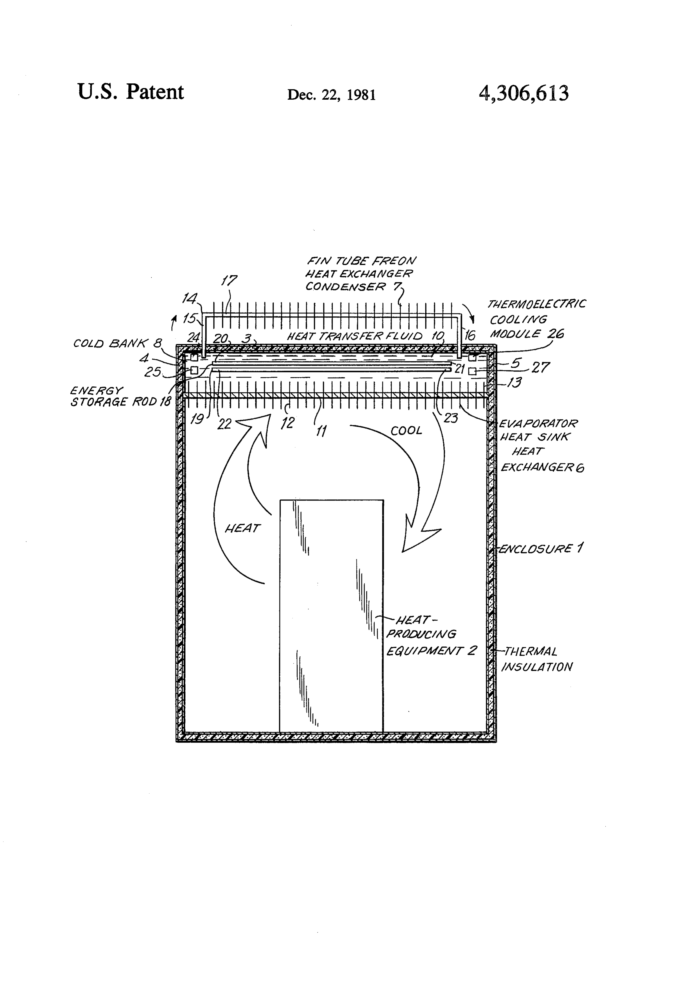
The outside heat exchanger comprises a fin tube heat exchanger condenser having an inverted substantially In order that the invention may be readily carried square U shaped finned tube with a pair of spaced sub into effect, it will now be described with reference to stantially parallel arms extending substantially perpen the accompanying drawing, wherein the single FIG dicularly to the top of the enclosure through the top 50 URE is a schematic diagram, partly in section, of an into the tank and a head extending between and joining embodiment of the passive cooling system of the inven the arms in spaced substantially parallel relation with tion.
the top of the enclosure. DETALED DESCRIPTION OF THE In accordance with the invention, a passive cooling INVENTION system for cooling an enclosure sheltering heat-produc 55 ing equipment, the enclosure having a top and spaced The passive cooling system of the invention cools an opposite sides, comprises a cold bank tank for storing enclosure 1 sheltering heat-producing equipment 2 such thermal energy in a very small area. The tank contains as, for example, any type of electrical or electronic liquid FREON and has a top which is the top of the equipment such as radio equipment, a microwave re enclosure and a spaced opposite bottom. An inside heat 60 peater station, or the like. The enclosure 1 has a top 3 exchanger extends from the bottom of the cold bank and spaced opposite sides 4 and 5.
tank in the enclosure for cooling warm air produced by The cooling system of the invention passively cools the equipment in the enclosure rising by natural convec the interior of the enclosure 1 without the consumption tion, returning the cooled air to the equipment in the of electrical energy in most applications. In areas of the enclosure and transferring the warm air to the cold bank 65 world where the nighttime temperatures are very high, tank wherein it warms the FREON in the tank. The a plurality of solid state thermoelectric modules, herein inside heat exchanger comprises an evaporator heat sink after described, are used for a limited period of the night type heat exchanger having extruded aluminum deep to supplement the passive cooling capacity. These sites
Page 5
are remote and unattended, so that the extremely high preferably a plurality of heads 17, connected at their levels of efficiency, reliability and maintenance-free ends to common manifolds which are, in turn, con characteristics of the cooling system of the invention nected to the arms 15 and 16. are important advantages. A suitable fin tube heat exchanger is that manufac The passive cooling system of the invention com tured by Edwards Engineering Corporation, 101 Alex prises three basic components; a heat exchanger 6 in the ander Avenue, Pompton Plains, N.J. 07444, and known enclosure 1, a heat exchanger condenser 7 outside the as a Valence Heat Exchanger. This heat exchanger has enclosure and a cold bank thermal energy storage sys six inch copper tubes connected in parallel by two tem 8, as hereinafter described. headers or manifolds on opposite ends of the 72 inch The cold bank 8 includes a cold bank tank 9 for stor 10 length. Aluminum fins are attached across the six cop ing energy in a very small volume. The tank 9 contains per tubes to dissipate heat contained in the vaporized a liquid heat transfer fluid 10, which is preferably liquid Freon in the copper tubes.
FREON, although it may be ammonia or other refriger In accordance with the invention, efficient phase ant. The heat transfer fluid 10 is preferably FREON, change energy storage rods are utilized to store large because the latent heat of absorption of FREON, when 15 amounts of thermal energy in a very small volumetric changing phase is considerably more efficient than wa area. A plurality of energy storage rods 18, 19, and so ter, when water is used as the heat transfer fluid in a on, of which only two rods 18 and 19 are shown in the thermosiphon type passive cooling system. Ammonia is FIG., are provided in the heat transfer fluid 10 in the even more efficient than FREON and has about three cold bank tank 9 for storing thermal energy in a very times the heat absorption capacity of an equal volume of 20 small area.
FREON 11, but is toxic. The energy storage rods 18, 19, and so on, are posi The cold bank tank 9 has a top which is the top 3 of tioned in substantially parallel relation with each other the enclosure 1 and a spaced opposite bottom 11. and with the top 3 of the enclosure 1. The energy stor The inside heat exchanger 6 extends from the bottom age rods 18, 19, and so on, have spaced opposite ends 11 of the cold bank tank 9 in the enclosure 1 and func 25 20, 21 and 22, 23, respectively, spaced from the spaced tions to cool warm air, produced by the equipment 2, in opposite sides 4 and 5 of the enclosure 1. the enclosure rising by natural convection. The inside The cold bank 8 stores thermal energy very effi heat exchanger 6 returns the cooled air to the equip ciently in a small area, since it uses the latent heat princi ment 2 in the enclosure 1 and tranfers the warm air to ple which permits a considerable amount of thermal the cold bank tank 9, where it warms the heat transfer 30 energy to be stored in the energy storage rods 18, 19, fluid 10 in said tank. and so on. The energy storage rods 18, 19, and so on, The inside heat exchanger 6 comprises an evaporator contain a eutectic salt solution and change phase at 81 heat sink type heat exchanger having extruded alumi F. and may comprise any suitable commercially avail num deep finned heat sinks 12 affixed to the bottom 11 able energy storage rods such as, for example, the of the cold bank tank 9 for heat transfer from the enclo 35 "Thermol 81 Energy Storage Rod' of Pipe Systems, sure 1 and deep finned sinks 13 extending from the heat Inc. available from Texxor Corporation of Omaha, sinks 12 and immersed in the heat transfer fluid 10 in Nebr. and Pace Corp. of Appleton, Wis. The liquid said tank at said bottom of said tank for thermal conduc FREON in the cold bank tank 9 functions as a highly tion. The heat sinks 13 conduct thermal energy effi efficient heat transfer fluid between the inside evapora ciently and prevent thermal stratification layers within 40 tor 6, the energy storage rods 18, 19, and so on, and the the tank 9. outside condenser 7.
The evaporator heat sink 6 is bonded to the cold bank Since heat is stored as latent heat of fusion in crystals 8 and forms an integral part thereof. The heat ex which change phase at 81 F., they absorb 82 BTU per changer 6 consists of four inch high extruded aluminum pound or 2460 BTU for each energy storage rod, which heat sinks 12 and 13 spaced about inch apart and cov 45 is 3 inches in diameter and 6 feet long. Because of the ering the entire bottom 11 of the cold bank tank 9 on the latent heat of fusion, large volumes of heat or cold may surface in the enclosure as well as on the surface in said be stored in very small volumes. Thus, if it is assumed, tank. The inside heat exchanger may comprise the Type for example, that the heat-producing equipment is a 4559-G manufactured by EG & G's Wakefield Engi radio repeater having a radio which dissipates 500 watts neering Company. 50 inside the enclosure, this would be equivalent to 1706 The outside heat exchanger 7 is outside the enclosure BTUH. If it is further assumed that the daytime period 1, spaced from the top 3 of said enclosure, and is cou is 11 hours, this is equivalent to 18,766 BTU total. To pled to the cold bank tank 9. The outside heat ex store 18,766 BTU in energy rods would require eight changer 7 comprises a fin tube heat exchanger con rods, since 18,766 BTU at 2460 BTU/rod=8. Each rod denser having an inverted substantially square U shaped 55 is 3.5 inches in diameter and 6 feet long, so that the eight finned tube 14. The tube 14 has a pair of spaced substan rods side by side, including spaces between the rods for tially parallel arms 15 and 16 extending substantially separation, would occupy 32 inches, for a total volume perpendicularly to the top 3 of the enclosure 1, and of 9,216 cubic inches or 5.4 cubic feet. By comparison, through said top into the cold bank tank 9. The tube 14 to store 18,766 BTU would require 500 gallons of water also has a head 17 extending between, and joining, the 60 which would require a tank with a volume about five arms 15 and 16 in spaced substantially parallel relation times larger than the volume of the energy storage rods. with the top 3 of the enclosure 1. Similarly, the inside heat exchanger 6, which is The outside heat exchanger condenser 7 may com bonded to the bottom of the cold bank tank 9, is 4 inches prise any suitable known device for performing the in height and the inside heat fins are also 4 inches, so described function. It is a conventional fin tube heat 65 that this heat exchanger adds 8 additional inches to the exchanger. The tube 14 is copper having an outer diam 4 inches required, in height, for the energy rods, for a eter of inch. The arms 15 and 16 of the tube 14 are total of 12 inches in overall height by 32 inches wide by copper having an outer diameter of 1 inches. There are 6 feet long. In order to hold the equivalent amount of
Page 6
heat storage in water within the same size enclosure, for with said energy storage rods and said top and side 5 of example, 32 inches wide by 6 feet long, the water tank said enclosure.
would have to be 4 feet in height. In addition, the The thermoelectric cooling modules 24, 25, 26, 27, enclosure's inside thermosiphon heat exchanger would and so on, are a multiplicity of solid state thermoelectric refrigeration modules immersed in the liquid FREON add an additional 1 feet in height, for a total of 6 feet in height, as compared to one foot for the cooling system 10 in the cold bank tank 9 and supplement the passive of the invention. cooling capacity during the infrequent nighttime peri Furthermore, the outside FREON heat exchanger 7 ods when the ambient temperature does not drop suffi dissipates 902 BTUH with a 16" temperature differential ciently to cool the energy storage rods 18, 19, and so on. for a total of 11,726 BTU over the 13 hour nighttime 10 A liquid FREON thermostat (not shown in the FIG.) period. To dissipate a total of 18,766 BTU would re senses this condition and automatically passes electric quire two of these heat exchangers. Somewhat less ity through the junction of the dissimilar metals in the cooling capacity is obtained from each unit when there thermoelectric modules. This causes heat to flow away are two, since the overall efficiency drops slightly be 15 from the junction. The heat is exhausted outside the cause of the reduction in the effective air temperature enclosure 1 by means of a 3 inch diameter exhaust pipe differential. Each of the two external heat exchangers is (not shown in the FIG.), thereby cooling the liquid 6 feet long by 14 inches wide by 2 inches high. The FREON 10 and storing cold energy in the energy stor two together, side by side, would occupy the same age rods 18, 19, and so on.
space requirements as the inside energy storage rods, 20 The thermoelectric cooling system utilizes very little for example, 32 inches wide by 6 feet long by 12 inches itpower, 50 to 100 watts, and is absolutely reliable, since does not require compressors or any of the other high, to provide 9 inches of free air circulation below complex the heat exchanger. The external heat exchangers units. piping coils traditionally found in refrigeration would also function as a solar roof, shading the top 3 of The thermoelectric solid state supplementary cooling the enclosure 1 from heat gains by solar radiation. modules are particularly useful in African type ambi Thus, the passive cooling system of the invention 25 ents, where the temperature differential between the would occupy a total of 6 feet long by 32 inches wide by day and nighttime periods is not as great as it is in a 2 feet in height, which is about the same size as an exec desert area, so that the modules therefore operate more utive's desk, of which 12 inches is inside the enclosure 1 frequently and for longer periods. Nevertheless, most of and 12 is outside the enclosure. By comparison, a water 30 the time the thermoelectric cooling modules would not based thermosiphon system would occupy a space 6 feet be operational, since the passive cooling system of the long by 32 inches wide by 9 feet in height, which is invention normally supplies sufficient cooling capacity. about the same size as five stacked executive desks, of The cooling system of the invention operates as foll which 6 feet is inside the enclosure, plus 3 feet for the lows. Heat dissipated from the equipment 2 rises and outside heat exchanger, or a difference in height of 7 35 flows by natural convection across the heat sink fins 12 feet. affixed to the bottom 11 of the cold bank tank 9, where The heat warming the liquid FREON 10 is trans the air is cooled and flows down across said equipment. ferred to the energy storage rods 18, 19, and so on, and Warm enclosure air is transferred into the cold bank when the outside temperature decreases below a prede or thermal storage tank 9 by means of the outer and termined magnitude, heat is released from said energy 40 inner cold bank heat sinks 12 and 13, which in turn storage rods to said FREON and vaporizes said warm the liquid FREON 10 and transfer this heat into FREON. The vaporized FREON flows through the the energy storage phase change rods 18, 19, and so on, outside heat exchanger 7, whence its heat is dissipated in immersed in said liquid FREON. Because the energy the outside air. The FREON vapor is recondensed by storage phase change rods 18, 19, and so on, store latent the condenser 7 and returns, by gravity force, to the 45 heat at 81 F., very large quantities of heat may be cold bank tank 9. The cold energy is stored in the en stored during the hot daytime period in a very small ergy storage rods 18, 19, and so on, for release when the aca.
air in the enclosure is next warmed. At night, when the outside temperature drops below A plurality of thermoelectric cooling modules 24, 25, 81 F., heat is released from the rods 18, 19, and so on, 26, 27, and so on, are provided in the heat transfer fluid 50 to the liquid FREON 10, which in turn vaporizes and 10 in the cold bank tank 9 and function to supplement flows upward through the tube arm 15 to the outside passive cooling. The supplementing of passive cooling heat exchanger 7, where the heat is dissipated in the is required during the infrequent nighttime periods cooler nighttime air. The recondensed liquid FREON when the temperature remains high. The thermoelectric then flows by gravity down the tube arm 16. The re cooling modules 24, 25, 26, 27, and so on, are solid state 55 turning chilled liquid FREON stores large amounts of components and may comprise any suitable cooling cold energy in the energy storage rods 18, 19, and so on, modules, which are commercially available. Thermo for release during the following hot daytime period. electric cooling modules of suitable type are manufac The passive cooling system of the invention may be tured by Koolatron Industries Limited, 56 Harvester built, as an alternative, as a fully integrated and insu Avenue, Batavia, N.Y. 14020, and are known as Koola 60 lated passive cooling package which may be mounted tron Miniaturized Thermoelectric Cooling Modules. on a roofless equipment enclosure either in the factory The thermoelectric cooling modules 24, 25, 26, 27, or at the site.
and so on, are positioned between the ends 20 and 22 of While the invention has been described by means of a the energy storage rods 18, 19, and so on, and the side 4 specific example and in a specific embodiment, I do not of the enclosure 1, in spaced relation with said energy 65 wish to be limited thereto, for obvious modifications storage rods and the top 3 and side 4 of said enclosure, will occur to those skilled in the art without departing and between the ends 21 and 23 of said energy storage from the spirit and scope of the invention. rods and the side 5 of said enclosure, in spaced relation I claim:
Page 7
1. A passive cooling system for cooling an enclosure ergy storage rods and the corresponding opposite sheltering heat-producing equipment, said enclosure sides of said enclosure in spaced relation with said having a top and spaced opposite sides, said cooling energy storage rods and the top and sides of said system comprising enclosure.
a cold bank tank for storing thermal energy in a very 5 2. A passive cooling system as claimed in claim 1, small area, said tank containing liquid FREON and wherein said cold bank tank, said inside heat exchanger having a top which is the top of the enclosure and and said outside heat exchanger are fully insulated and a spaced opposite bottom; form an integral unit for mounting on an enclosure. an inside heat exchanger extending from the bottom 3. A passive cooling system for cooling an enclosure of said cold bank tank in said enclosure for cooling 10 having a top, said cooling system comprising warm air produced by the equipment in said enclo a cold bank tank for storing thermal energy in a very sure rising by natural convection, returning the small area, said tank containing a liquid heat trans cooled air to the equipment in the enclosure and fer fluid and having a top which is the top of the transferring the warm air to said cold bank tank enclosure and a spaced opposite bottom; wherein it warms the FREON in said tank, said 15 an inside heat exchanger extending from the bottom inside heat exchanger comprising an evaporator of said cold bank tank in said enclosure for cooling heat sink type heat exchanger having extruded warm air in said enclosure rising by natural con aluminum deep finned heat sinks affixed to the vection, returning the cooled air to the enclosure bottom of said cold bank tank for heat transfer and transferring the warm air to said cold bank from said enclosure and deep finned heat sinks 20 tank wherein it warms the heat transfer fluid in said extending therefrom and immersed in said FREON tank, said inside heat exchanger comprising an in said tank at the bottom of said tank for thermal evaporator heat sink type heat exchanger having conduction and to prevent thermal stratification deep finned heat sinks affixed to the bottom of said layers within the tank; cold bank tank for heat transfer from said enclosure an outside heat exchanger outside said enclosure, 25 and deep finned heat sinks immersed in said heat spaced from the top of said enclosure and coupled transfer fluid in said tank at the bottom of said tank to said cold bank tank, said outside heat exchanger for thermal conduction and to prevent thermal comprising a fin tube heat exchanger condenser stratification layers within said tank; having an inverted substantially square U shaped an outside heat exchanger outside said enclosure finned tube with a pair of spaced substantially par 30 spaced from the top of said enclosure and coupled allel arms extending substantially perpendicularly to said cold bank tank;
to the top of said enclosure through said top into a plurality of energy storage rods in said heat transfer said tank and a head extending between and joining fluid in said cold bank tank for storing thermal said arms in spaced substantially parallel relation energy in a very small area whereby the heat with said top of said enclosure; 35 warming said heat transfer fluid is transferred to a plurality of energy storage rods in said FREON in said energy storage rods and when the outside said cold bank tank for storing thermal energy in a temperature decreases below a predetermined very small area, said energy storage rods being magnitude, heat is released from said energy stor positioned in substantially parallel relation with age rods to said liquid heat transfer fluid and vapor each other and with said top of said enclosure, said izes said fluid, the vaporized heat transfer fluid energy storage rods having spaced opposite ends flowing through the outside heat exchanger spaced from the spaced opposite sides of said en whence its heat is dissipated in the outside air and closure whereby the heat warming said FREON is said heat transfer fluid is recondensed and returns transferred to said energy storage rods and when by gravity force to said tank thereby storing cold the outside temperature decreases below a prede 45 energy in said energy storage rods for release when termined magnitude, heat is released from said the air in said enclosure is next warmed, said enclo energy storage rods to said liquid FREON and sure having spaced opposite sides and said energy vaporizes said FREON, the vaporized FREON storage rods having spaced opposite ends spaced flowing through the outside heat exchanger from said spaced opposite sides; and whence its heat is dissipated in the outside air and 50 a plurality of thermoelectric cooling modules in said said FREON is recondensed and returns by gravity heat transfer fluid in said cold bank tank for supple force to said tank thereby storing cold energy in menting passive cooling, said thermoelectric cool said energy storage rods for release when the air in ing modules being positioned between the ends of said enclosure is next warmed; and said energy storage rods and the corresponding a plurality of thermoelectric cooling modules in said 55 opposite sides of said enclosure in spaced relation FREON in said cold bank tank for supplementing with said energy storage rods and the top and sides passive cooling, said thermoelectric cooling mod of said enclosure.
ules being positioned between the ends of said en :k k sk k ak
Provenance
- Collection
- Cited prior art
- Original PDF
- patentimages.storage.googleapis.com →
- Filed
- 1980-03-10
- Pages
- 7
- Method
- pdftotext (the PDF's own text layer) + pdftoppm 300dpi page scans
- Source
- Google Patents bibliographic record
- Granted
- 1981-12-22
- Inventors
- Nicholas S. Christopher
- Transcribed from
- patentimages.storage.googleapis.com →