patent · US4317031
Central focus solar energy system
23 February 1982
Page 1 — bibliographic record
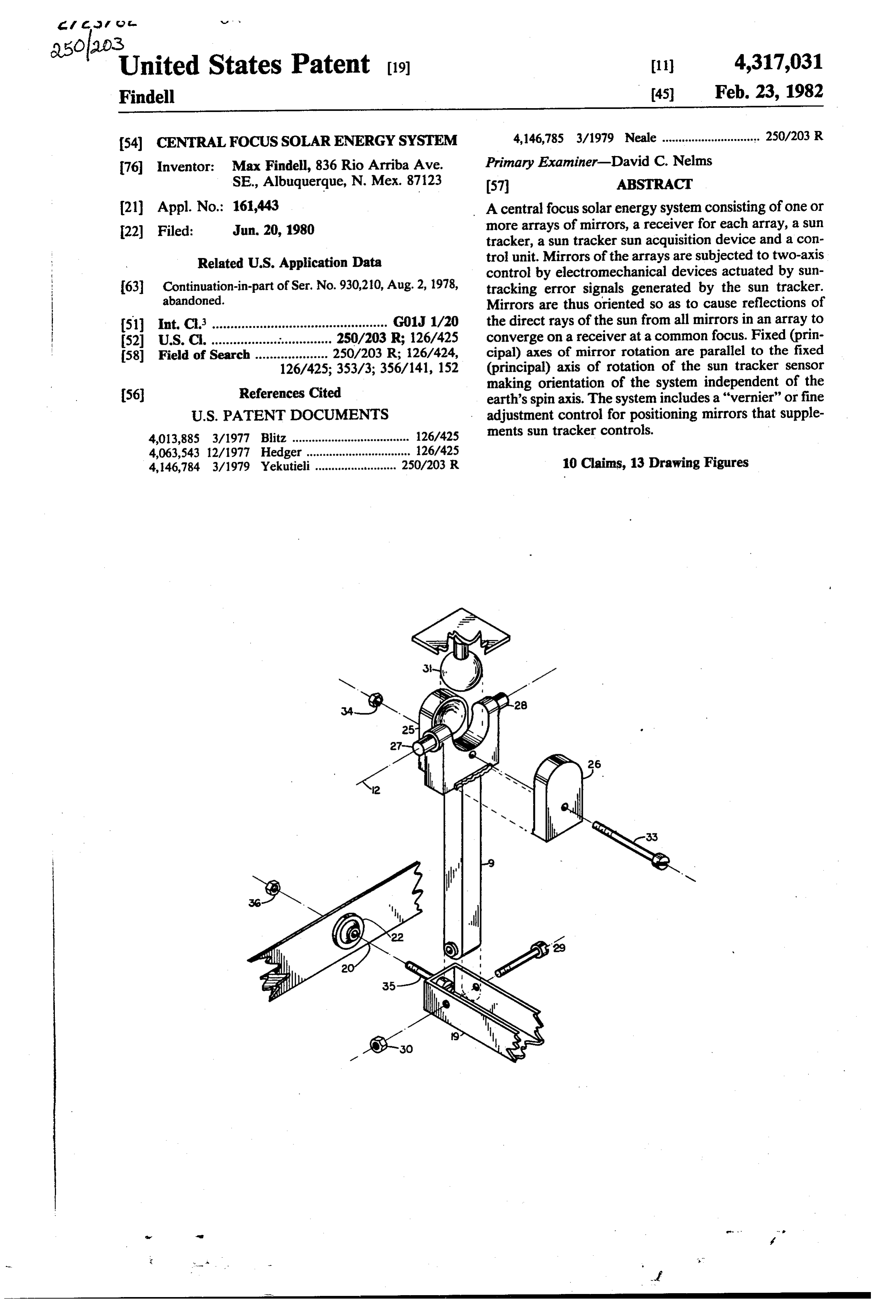
. States Patent (19) (11) 4,317,031 Findell (45) Feb. 23, 1982 (54) CENTRAL FOCUS SOLARENERGYSYSTEM 4,146,785 3/1979 Neale .............................. 250/203 R 76 Inventor: Max Findell, 836 Rio Arriba Ave. Prinary Examiner-David C. Nelms SE., Albuquerque, N. Mex. 87123 57 ABSTRACT (21) Appl. No.: 161,443 A central focus solar energy system consisting of one or 22) Filed: Jun. 20, 1980 more arrays of mirrors, a receiver for each array, a sun tracker, a sun tracker sun acquisition device and a con
Related U.S. Application Data trol unit. Mirrors of the arrays are subjected to two-axis control by electromechanical devices actuated by sun 63 Continuation-in-part of Ser. No. 930,210, Aug. 2, 1978, tracking error signals generated by the sun tracker. abandoned. Mirrors are thus oriented so as to cause reflections of (51) Int. C. ................................................ G01J 1/20 the direct rays of the sun from all mirrors in an array to 52 U.S. C. ................................ 250/203 R; 126/425 converge on a receiver at a common focus. Fixed (prin 58 Field of Search .................... 250/203 R; 126/424, cipal) axes of mirror rotation are parallel to the fixed 126/425; 353/3; 356/141, 152 (principal) axis of rotation of the sun tracker sensor
References Cited making orientation of the system independent of the (56) earth's spin axis. The system includes a "vernier" or fine
4,013,885 3/1977 Blitz. .................................... 126/425 ments sun tracker controls.
4,063,543 12/1977 Hedger ................................ 126/425 4,146,784 3/1979 Yekutieli......................... 250/203 R 10 Claims, 13 Drawing Figures
Page 2
Drawing sheet — no readable text.
Page 3
Drawing sheet — no readable text.
Page 4
Drawing sheet — no readable text.
Page 5
Drawing sheet — no readable text.
Page 6
Drawing sheet — no readable text.
Page 7
Drawing sheet — no readable text.
Page 8
Drawing sheet — no readable text.
Page 9
Drawing sheet — no readable text.
Page 10
Drawing sheet — no readable text.

Page 11
that all mirrors may be simultaneously and equally
CENTRAL FOCUS SOLAR ENERGY SYSTEM rotated about either one or both of two axes of rotation.
This application is a continuation-in-part of Ser. No. 5 Mirror support fixtures, which are pivotably mounted in fixed frameworks or other structural 930,210 filed Aug. 2, 1978, now abandoned. members to rotate about what are called mirror BACKGROUND OF THE INVENTION "principal axes' of rotation in this invention. Prin Central focus solar energy collectors include circular cipal axes for all mirrors are parallel to one another concentrators and heliostats. Typically a circular con O and parallel to the earth's spin axis. centrator has a segmented or continuous parabolic-dish A second axis of rotation for each mirror which is mirror or fresnel lens to concentrate the direct solar termed "secondary axis" in this application. These output on a receiver which is located at the focal point secondary axes are perpendicular to, intersect and of the parabolic dish or fresnel lens. Heliostats (as in this rotate about principal axes. invention) consist of a plurality of flat (or nearly flat) A means for initially adjusting or focusing each mir mirrors which are subjected to two-axis control to ror so that during system operation, reflections of cause reflections of the direct rays of the sun from all the direct rays of the sun from all mirrors converge mirrors to converge on a receiver. Concentrating solar at a common focus.
energy in these ways, central focus solar energy systems Electromagnetic or other drive mechanisms for rotat typically operate at from 1000' F. to 2500' F. which is 20 ing all mirrors about their principal axes in accor much higher than the nominal 150' F. provided by dance with diurnal (i.e., time-of-day) changes in the flat-plate collectors or the 500' F. characteristic of lin apparent position of the sun. ear focus (parabolic trough) collectors, Heat is normally Electromagnetic or other drive mechanisms for rotat transferred from the receiver (or absorber) using a suit ing all mirrors about their secondary axes to cope able operating fluid for storage and/or use in a thermal 25 with seasonal changes in the sun's declination an to-electric conversion system. Concentrator photovol gle, taic cells, which directly convert some of the concen The parallel orientation of mirror principal axes of trated direct rays of the sun into electricity, may also be rotation with respect to the earth's spin axis is very installed on the central focus system receiver. Using critical for these heliostats. The smallest misalignment concentrated solar energy in this way, a given electrical 30 in this regard power demand may be met with fewer expensive photo changes in the results in a condition wherein diurnal voltaic cells than would otherwise be required with no accomodated solely by position apparent of the sun cannot be concentration. Typically silicon concentrator cells op principal axes and declination anglesmirrors rotating solely about their by rotations erate at from 12% to 23% efficiency in converting solar about mirror secondary axes. Rather, for example, energy to electricity at concentrations of from 25 to 100 35 angle changes in the apparent position of the sun,hour will suns. AlGaAs cells have a reported potential efficiency require rotation about both mirror principal and sec of up to 25% at from 50 to 2000 suns. In the photovol taic cell configuration, air or an operating fluid flowing ondary axes to maintain sun reflections from all mirrors thru the receiver, cools the photovoltaic cells for higher onThis the common focus.
criticality of alignment factor has greatly limited solar-to-electrical conversion efficiencies and transfers 40 heat to a thermal storage unit. the practical use of heliostats. Thus advantages of central focus collectors over One objective of the present invention is to provide a other solar energy systems include the following: central focus solar energy (heliostat) system which may Higher operating temperatures than possible with be randomly oriented with respect to the earth's spin flat-plate or linear focus collectors permitting: 45 axis. With the criticality of alignment factor removed, Higher thermal-to-electric conversion efficiencies this invention offers a broad potential for satisfying Smaller thermal energy storage subsystems energy needs. For example, systems making use of this More extensive industrial use of solar energy invention may be installed, using home-construction Optional use of concentrator (as apposed to conven skills, in or on virtually any new or existing structure tional) photovoltaic cells at high sun concentra (with reasonable exposure to the direct rays of the sun) tions, thereby reducing the cost of generating elec 50 to meet electrical and space and water heating needs. tricity thru the direct conversion of solar energy to In addition to the criticality of alignment factor, other electricity, reasons why heliostats have not been used extensively DESCRIPTION OF THE PRIOR ART to meet energy requirements are that they are charac
teristically relatively complex, expensive to produce
The following relevant U.S. Patents for heliostats and maintain and inherently unreliable. Accordingly, were disclosed during a novelty search: yet another objective of this invention is to provide a central focus solar energy system which is, by compari son, simple, has a potential for high reliability and is
U.S. Pat. No. Inventor Issue Date inexpensive to produce and maintain.
509,390 Paine 11/28/893 Another objective of the present invention is to pro 3,466,119 Francia 9/09/969 vide a fundamental design which may be applied flexi 4,056,313 Arbogast 1/01/1977 bly to assemble central focus solar energy systems of virtually any desired capacity to meet a variety of en
Characteristically these heliostats include the follow 65 ergy needs.
ing: Still another objective of the present invention is to A plurality of flat (or nearly flat) mirrors which are provide a sun tracker and receiver which uniquely con pivotably mounted and mechanically coupled so trol rotations of a plurality of mirrors to maintain reflec
Page 12
tions of the direct rays of the sun from all mirrors on a The receiver for each array of mirrors is normally receiver at the common focus. centered over the array at a distance which is great SUMMARY OF THE PRESENT INVENTION enough to preclude reflections of the direct rays of the sun from any mirror of the array illuminating the back
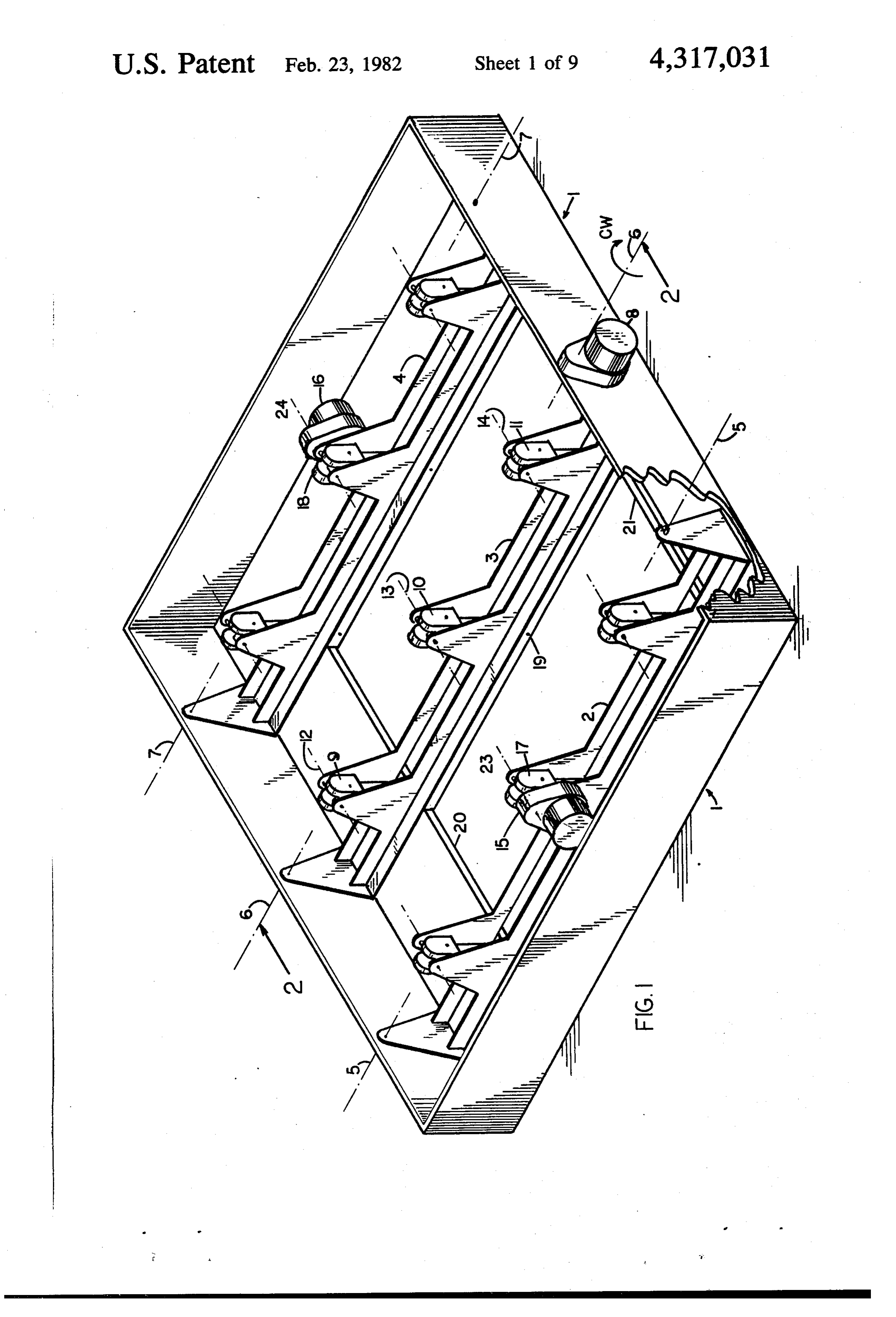
The above and other objectives are met in the present 5 of an adjacent mirror. The distance is a function of the invention for a central focus solar energy system with number and size of array mirrors and the separation one or more arrays of mirrors, a receiver centered over distance between mirrors. In general receivers for ar each array, a sun tracker, a sun tracker sun-aquisition rays with small mirrors (for example: square mirrors device and a control unit. Array mirrors are subjected measuring 5 cm or less on a side) may be positioned to two-axis control by the sun tracker, the receiver or O inside of transparent protective covers. It is usually sun tracker sun-acquisition device thru the control unit more practical to have receivers outside of protective to cause reflections of the direct rays of the sun from all covers for arrays with larger mirrors. mirrors of each array to converge of the receiver for Other objectives, applications and unique features of that array. the present invention become apparent from the De Like heliostats previously discussed, mirrors included 15 scription of the Preferred Embodiment. in arrays of the present invention are pivotably mounted BRIEF DESCRIPTION OF DRAWINGS to rotate about fixed, parallel principal axes and second ary axes which are perpendicular to, intersect and ro FIG. 1 is an isometric view of a typical mirror array tate about these principal axes. While mechanical cou with mirrors removed.
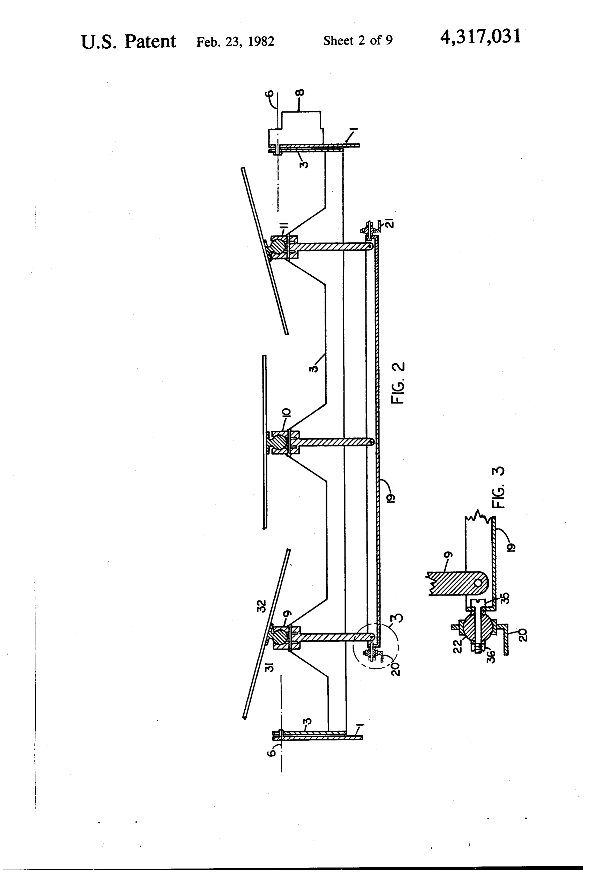
pling, mirror focusing and other means in the present 20 FIG. 2 is a sectional view of the mirror array of FIG. invention and referenced heliostats are dissimilar, the 1.
main differences in the present invention are the inclu FIG. 3 is an enlarged sectional view of a portion of sion of a sun tracker and a receiver-mounted mirror FIG. 2.
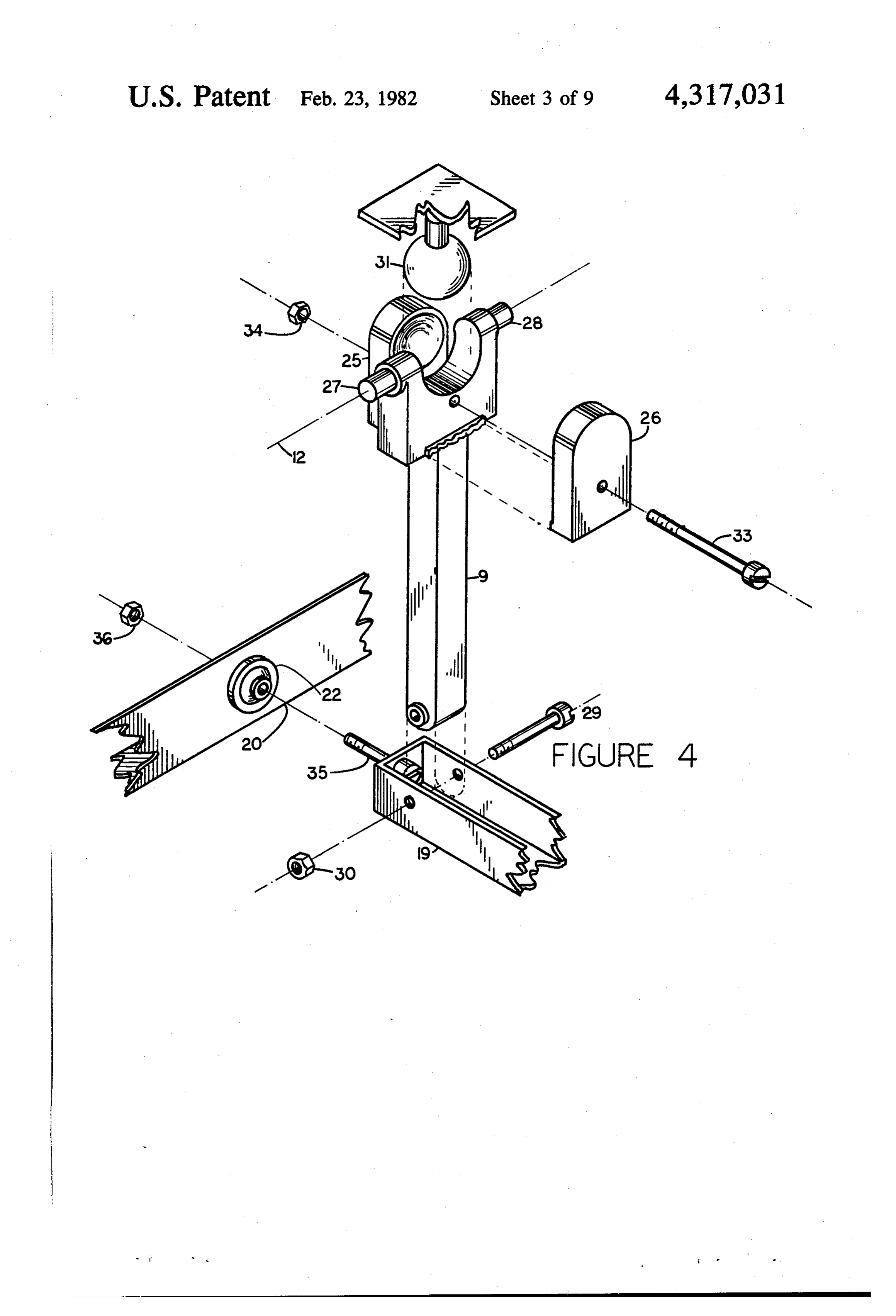
reflection feed-back system. FIG. 4 is an isometric view of a mirror articulating The sun tracker provides one means for controlling 25 arm and associated components.
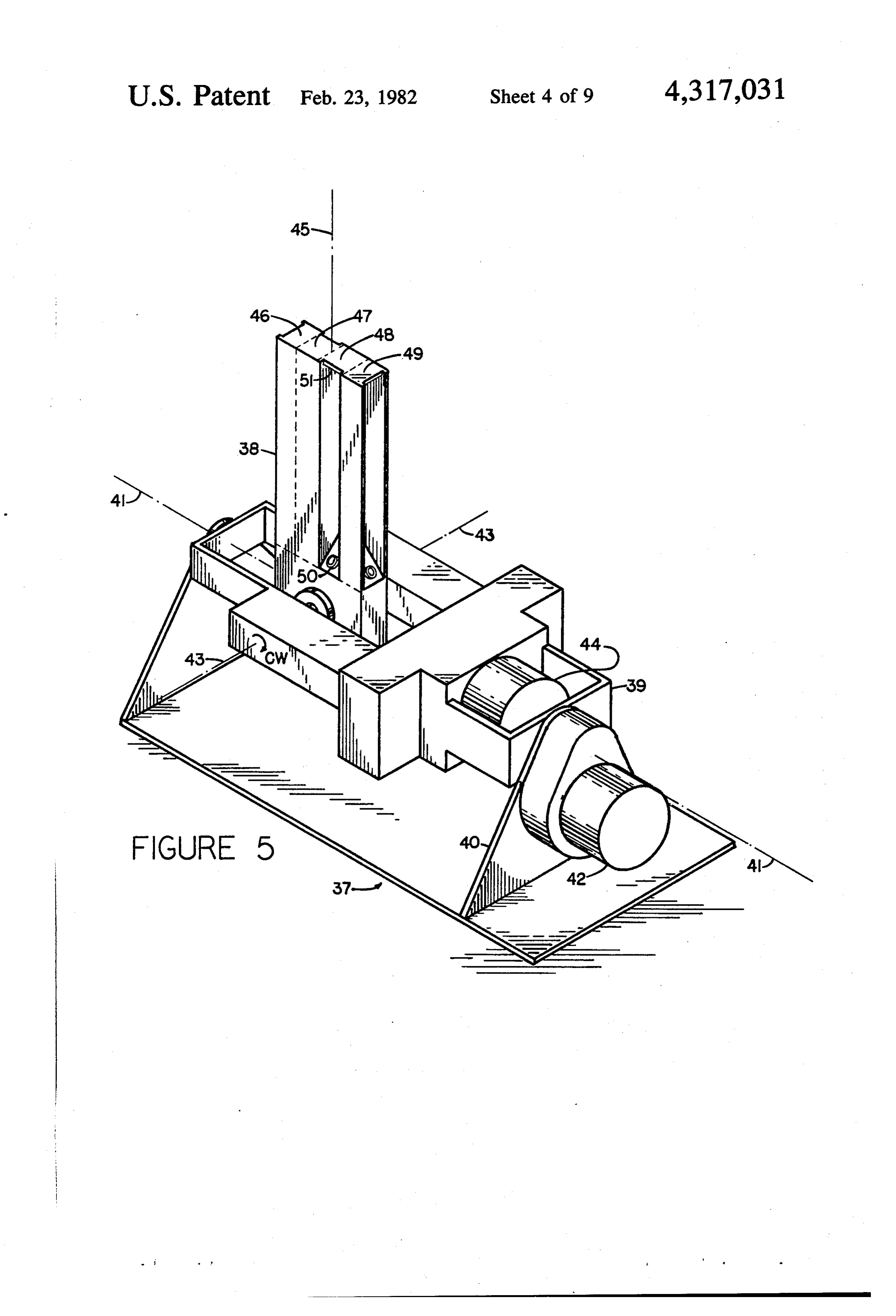
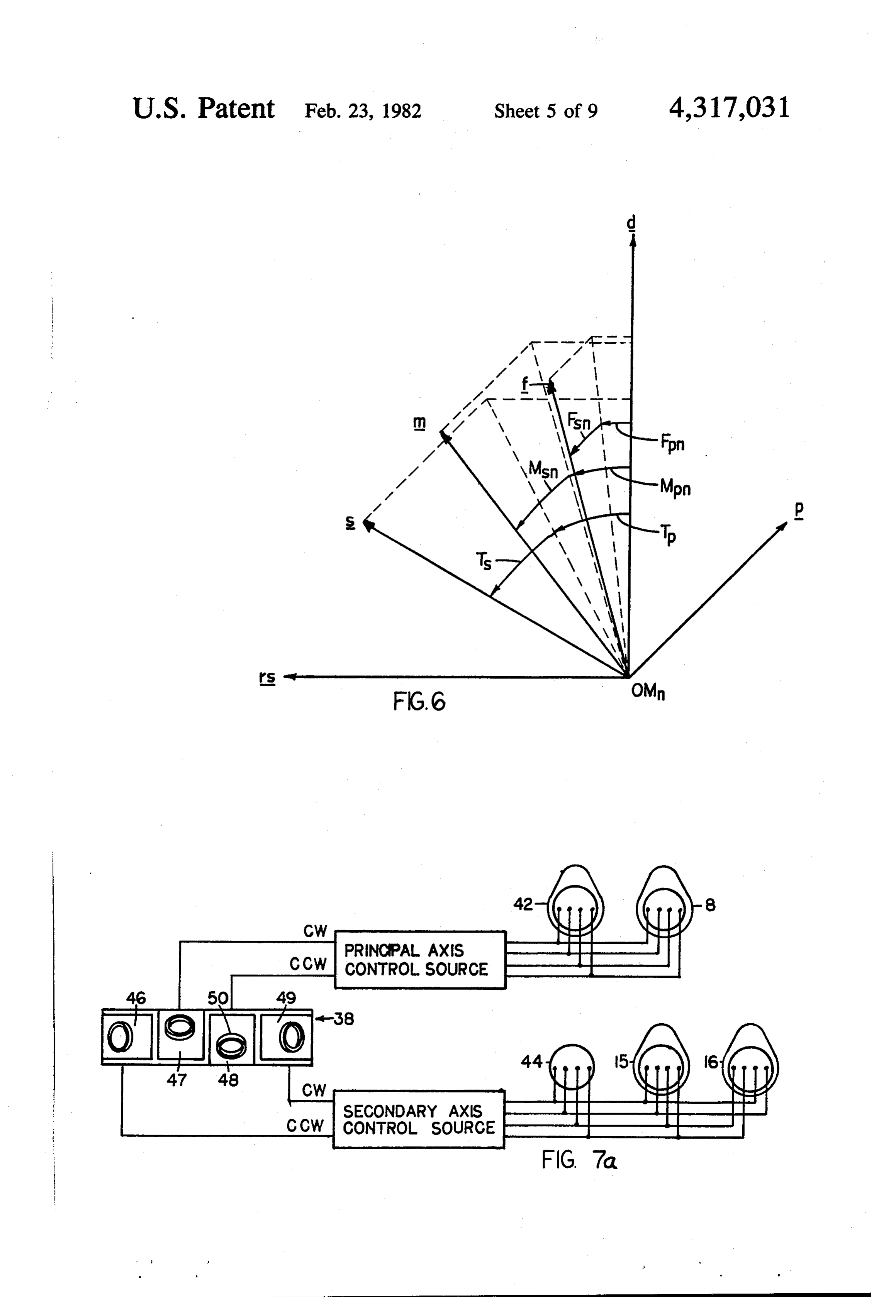
mirror rotations. Sun-tracking error signals, generated FIG. 5 is an isometric view of the sun tracker. by the sun tracker sensor, are inputs to the control unit FIG. 6 is a diagram of the sun-mirror-common focus which sends command pulses to stepping motors caus geometry.
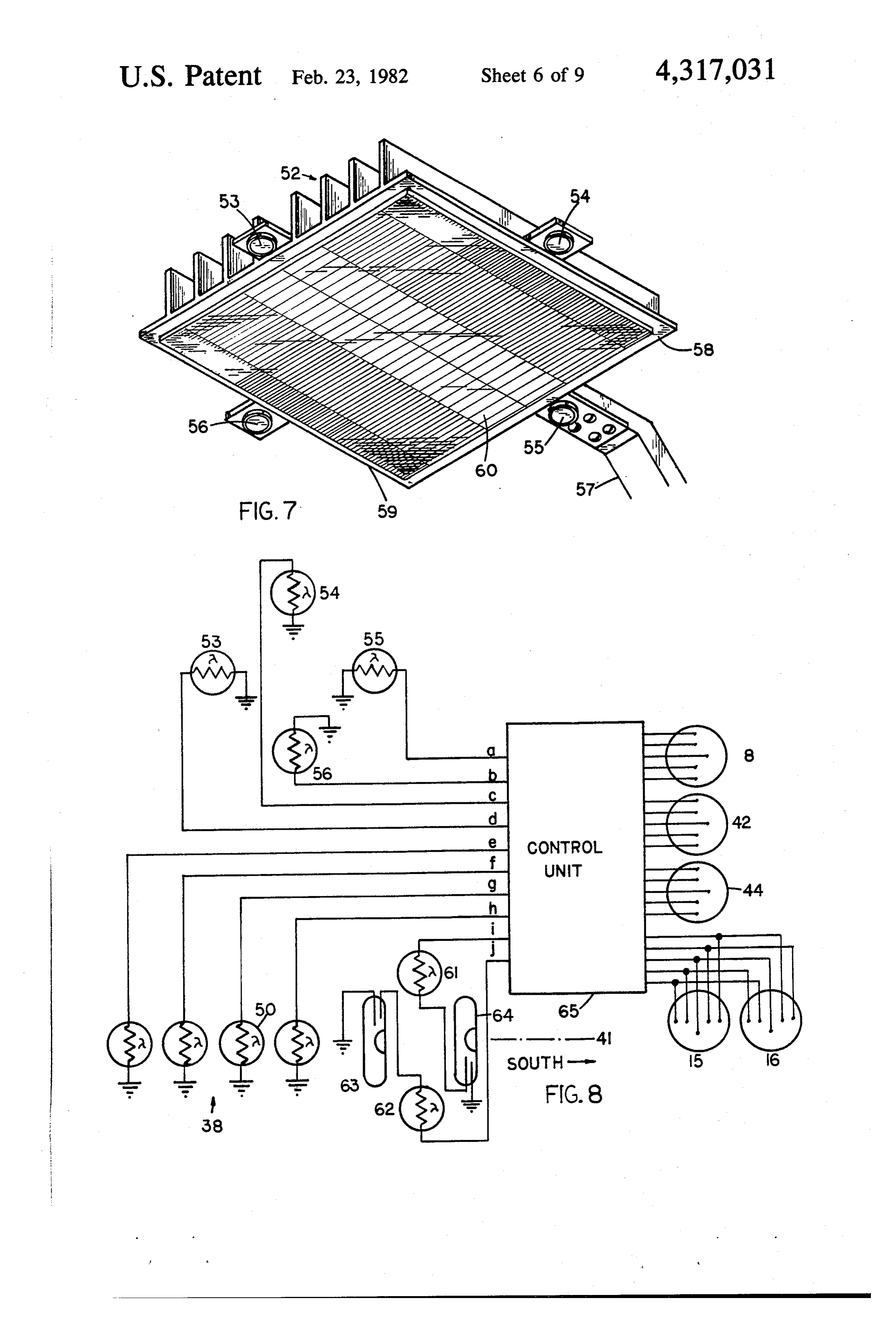
ing the sensor to rotate to eliminate sun tracking errors. FIG. 7 is an isometric view of a typical air-cooled These same command pulses are also transmitted to 30 receiver.
mirror control stepping motors causing all mirrors to FIG. 7a is a simplified block diagram of sensing and simultaneously rotate in the same direction about corre control units.
sponding axes. The sun tracker sensor is pivotably FIG. 8 is a simplified block diagram of the electrical mounted to rotate about a "sensor principal axis' with a system.
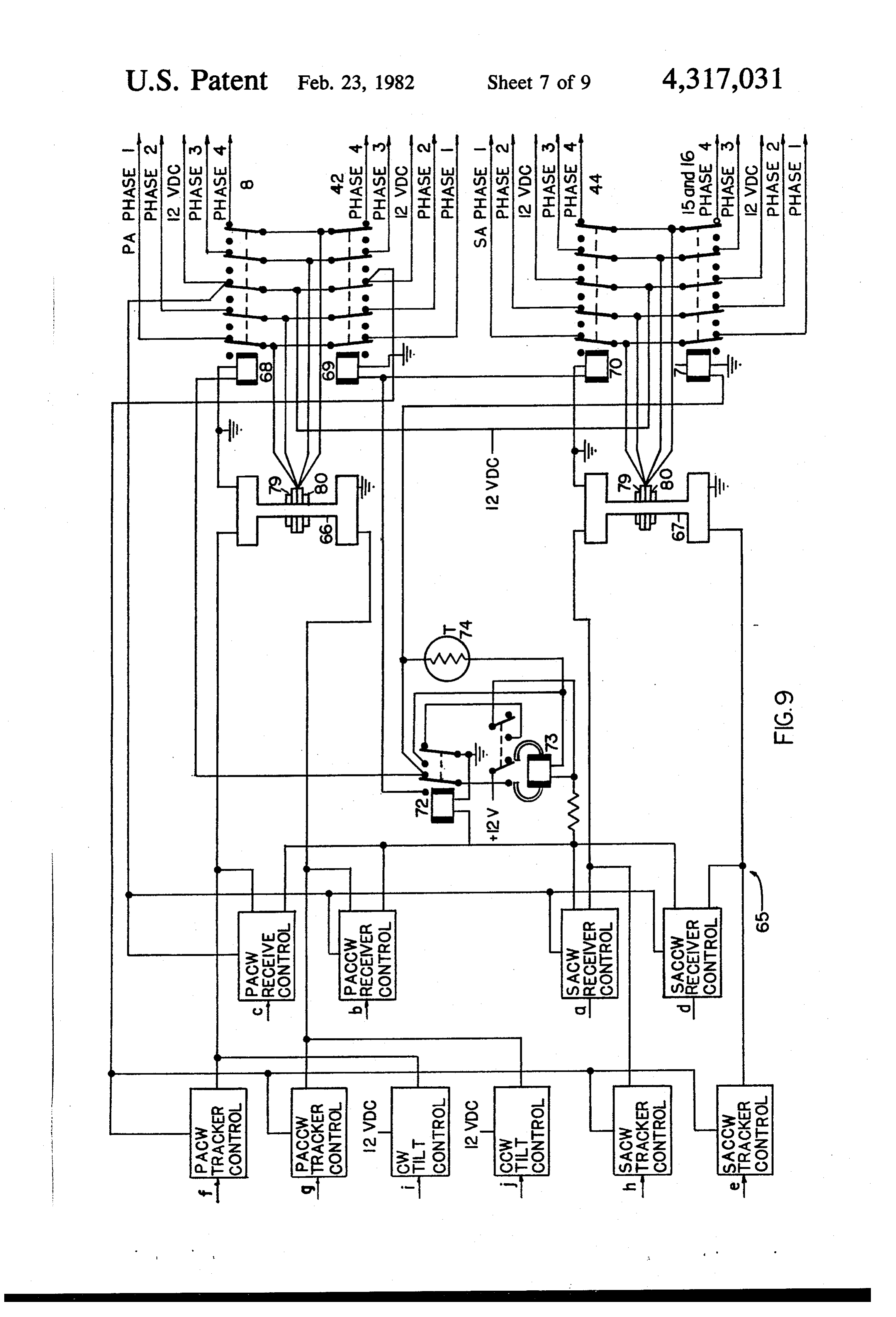
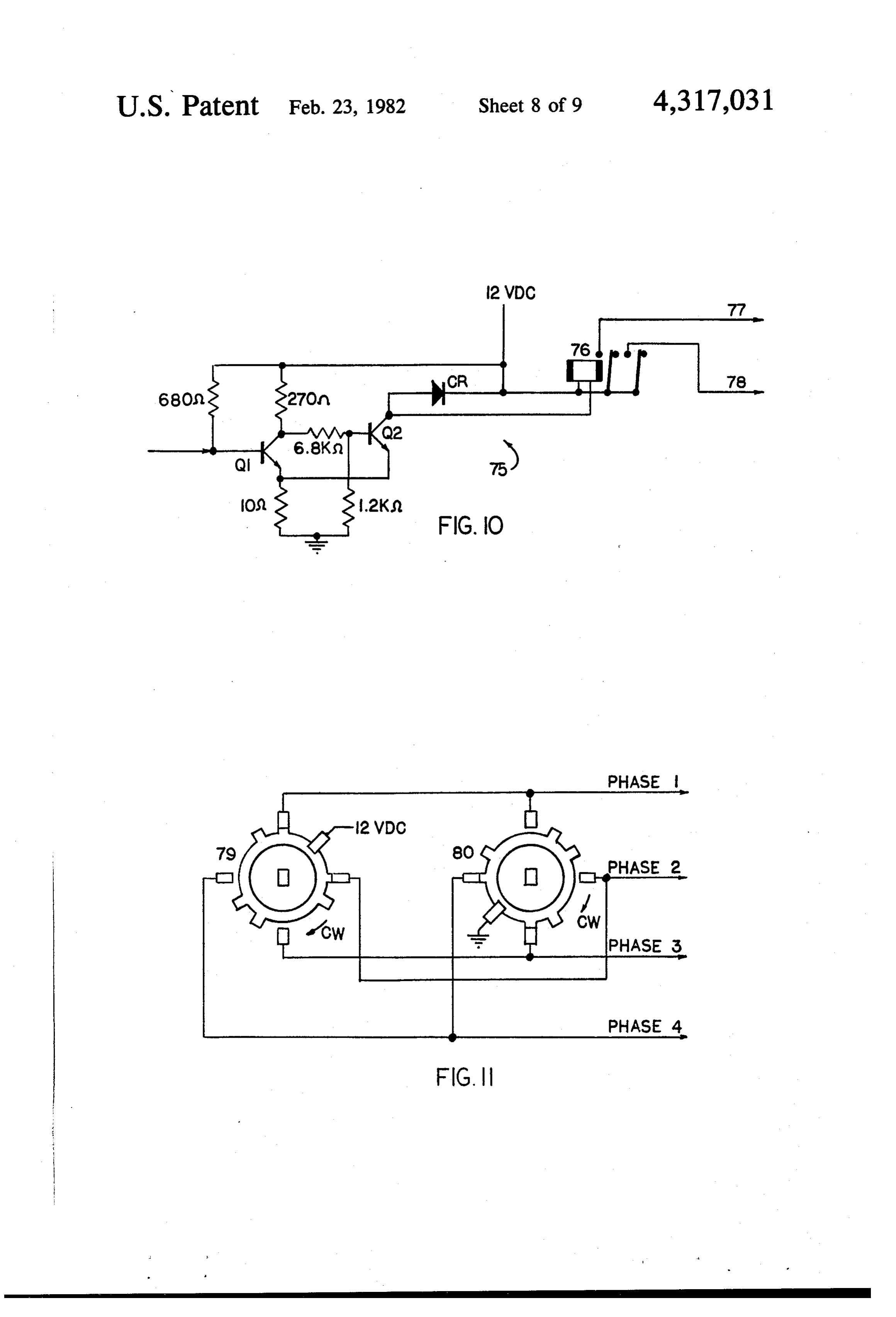
fixed orientation in the sun tracker and a "sensor sec 35 FIG. 9 is a simplified block diagram of the control ondary axis" which is perpendicular to, intersects and unit rotates about the sensor principal axis. As a primary FIG. 10 is a block diagram of a typical control ele design requirement of the present invention, all mirror ment principal axes must be parallel to the sensor principal FIG. 11 is a diagram of two rotary switch sections axis. It is not required that these principal axes be paral FIG. 12 is an isometric view of principal components lel to the earth's spin axis. As long as mirror principal of the present invention typically assembled into a small axes are parallel to the sun tracker sensor principal axis central focus solar energy system there is no limit to the number of mirrors that may be controlled by the sun tracker thru the control unit. Also DESCRIPTION OF THE PREFERRED there is nothing in the design that limits the size of 45 EMBODIMENT mirrors used in arrays or dictates the separation distance FIG. 1 shows a typical mirror array with mirrors of mirrors and the receiver. removed to expose mechanical coupling means. Details The receiver-mounted mirror reflection feed-back regarding mirror installations are provided later. The system provides a "vernier' control capability for the mirror array supported by framework 1 includes three system. Following initial mirror positioning under sun 50 mirror principal axis control brackets 2, 3 and 4. Brack tracker control, this vernier control system causes fur ets 2 and 4 are pivotably mounted at both ends in frame ther mirror orientation adjustments to center mirror work 1 to rotate about mirror principal axes of rotation reflections of the direct rays of the sun on the receiver 5 and 7. Bracket 3 is a shaft-coupled to mirror principal surface. axis control motor 8 at one end and pivotably mounted For most applications, environmental protection is 55 in framework 1 at the other end, to rotate about mirror provided system components thru the use of transparent principal axis of rotation 6. Motor 8 is mounted on glass or plastic covers. Such covers should practically framework 1 and provides a means for rotating bracket eliminate system maintenance requirements and and 3 in either a clockwise (CW) or counterclockwise enhance system reliability without significantly reduc (CCW) direction about axis 6. Axes 5, 6 and 7 are paral ing the amount of solar energy available to the system. lel and in a common plane.
The underside of system arrays is enclosed using either Three mirror articulating arms, 9, 10, and 11 for ex an opaque or translucent material to shield out all, or ample, are pivotably mounted between mirror-image most of, the sunlight passing between mirrors; or trans sides of each bracket, bracket 3 for example, for rotation parent plastic or glass to permit residual direct rays and about mirror secondary axes of rotation 12, 13, and 14. the diffuse component of solar radiation to pass thru the 65 Mirror secondary axes of rotation for all arms on a arrays. The latter configuration lends itself to cathedral given bracket are in a common plane and are perpendic ceiling installations in dwellings or use of mirror arrays ular to and intersect the mirror principal axis of rotation in a greenhouse roof. about which that bracket rotates. Axes 12, 13, and 14
Page 13
are in a common plane and are perpendicular to and ened. All other array mirrors are similarly coupled to intersect axis 6. As later described in detail, a mirror is articulating arms and focused. coupled to each mirror articulating arm. After the initial Referring to FIGS. 5 and 7a, and sun tracker 37 mirror-focusing adjustment, which is also reviewed tracks the sun by rotating the sun tracker sensor 38 later, angular changes in the position of all mirrors is about two orthogonal axes of rotation, identified as made thru mirror articulating arms. Secondary axis sensor principal axis 41 and sensor secondary axis 43. control motors 15 and 16 are mounted on brackets 2 and Gimbal 39 is pivotably mounted in support 40 to 4 and are shaft-coupled to arms 17 and 18 respectively. rotate about sensor principal axis 41. Sensor principal Mirror arrays are not restricted to the three brackets, 10 axis control motor 42 is mounted on support 40 and three articulating arms per bracket or three motors provides a means for rotating gimbal 39 about axis 41 in either a clockwise or counterclockwise direction.
shown in FIG. 1.
All articulating arms in the array are dimensionally Sun tracker sensor 38 is pivotably mounted in gimbal identical and, as shown in FIG. 2 for bracket 3, all arms39 for rotation about sensor secondary axis 43. Sensor mounted on a given bracket are pivotably coupled near secondary axis control motor 44, mounted in gimbal 39, the base of the arm to a mirror control bar 19. Corre 15 thru a suitable gear train (not shown) provides a means for rotating sensor 38 about axis 43 in either a clockwise sponding ends of each mirror control bar in an array are or coupled by tie rods 20 and 21. Referring to FIG. 3, counterclockwise direction. Axis 43 is perpendicular to axis 41, intersects axis 41 at the center of rotation of bar-to-tie rod couplings include a spherical bearing, for sensor example 22, to insure a snug, two-axis union. 38 and rotates about axis 41 with gimbal 39. The 20 sensor longitudinal axis 45 is perpendicular to the plane
Returning to FIG. 1, all mirrors of the array are of axes 41 and 43 and passes thru the center of rotation rotated about mirror principal axes of rotation by motor of sensor 38.
8 thru the hereinbefore described mechanical coupling Sensor 38 includes four contiguous compartments: means as follows: When activated, motor 8 rotates bracket 3 and mirror control bar 19 about axis 6 in either 25 46, 47, 48 and 49. Each compartment includes a light sensitive device. Light-sensitive devices detect sun a clockwise or counterclockwise direction. Tie rods 20 tracking errors. A sun-tracking error is defined as any and 21 mechanically transmit this rotational movement misalignment of longitudinal axis 45 and a straight line to all other mirror control bars in the array causing the connecting the sensor center of rotation and the center simultaneous and equal rotation of brackets 2 and 4 of the sun. A sun-tracking error, detected by one of about axes 5 and 7 respectively. This rotational move 30 these light-sensitive devices and transmitted to the con ment is transmitted mechanically to all mirror articulat trol unit (described later in detail), causes either motor ing arms causing all to simultaneously and equally ro 42 or motor 44 to rotate sensor 38 to eliminate the error. tate about their respective principal axes. An example of how the sun tracker operates follows: Array mirrors are rotated about mirror secondary Light-sensitive device 50 is mounted in compartment axes of rotation by secondary axis control motor 15 and 35 48. Sun-shadowing fence 51, at the sun end of compart 16 as follows: When activated, motors 15 and 16 simul ment 48, shades device 50 from the direct rays of the sun taneously and equally rotate arms 17 and 18 in the same under a condition of no sun-tracking error. Should the direction about mirror secondary axes of rotation 23 apparent position of the sun change so as to cause de and 24 respectively. This rotational movement is me vice 50 to be illuminated by the direct rays of the sun, chanically transmitted thru mirror control bars 19 and device 50 will generate a sun-tracking error signal, tie rods 20 and 21 causing the simultaneous and equal causing motor 42 to rotate gimbal 39 and sensor 38 in a rotation of all mirror articulating arms (and coupled counterclockwise direct (as viewed from motor 42) mirrors) about their respective secondary axes of rota about axis 41 until fence 51 again shades device 50 from tion. At least two mirror secondary axis control motors the direct rays of the sun.
are required for each array to insure equal movement of 45 Sun-tracking errors detected by light-sensitive de all mirror control bars. Note that in order to rotate all vices included in other compartments cause the sensor arms in the same direction, shafts of motors 15 and 16 38 to be rotated in other directions. An error detected must rotate in opposite directions, as viewed from the by the light-sensitive device installed in compartment back of each motor. 47 (termed: a compartment 47 error) causes motor 42 to Mirror articulating arm 9 and associated components 50 rotate the sensor about axis 41 in a clockwise direction. are shown in FIG. 4. The two halves of the mirror A compartment 46 error causes motor 44 to rotate the focusing ball sockets 25 and 26 are part of arm 9. Arm sensor about axis 43 in a counterclockwise direction. 9 is pivotably mounted in bracket 3 by inserting second The clockwise direction about axis 43 is indicated by ary axis shafts 27 and 28 into shaft holes in bracket 3. CW in FIG. 5. A compartment 49 error causes motor 44 Mirror control bar 19 is attached to the base of arm 9 55 to rotate the sensor about axis 43 in a clockwise direc using machine screw 29 and secured by nut 30. Mirror tion.
focusing ball 31 with mirror 32 attached (FIG. 2) is It should now be recalled that mirror principal axis installed between and in the ball recesses of ball socket control brackets (FIG. 1) are pivotably mounted in halves 25 and 26. Machine screw 33 is inserted thru arm framework 1 to rotate about mirror principal axes and 9 and nut 34 tightened to couple ball 31 to arm 9. Tie the sun tracker gimbal 39 is pivotably mounted in sup rod 20 is coupled to bar 19 by inserting machine screw port 40 to rotate about sensor principal axis 41. As a 35 thru bar 19 and spherical bearing 22 and tightening primary requirement of this invention, the sensor princi nut 36. To focus mirror 32, nut 34 is loosened to permit pal axis 41 must be parallel to all mirror principal axes the rotational movement of ball 31 in the ball socket. (i.e., axes 5, 6, and 7). Since the sun's rays are essentially Mirror 32 is then manually positioned by rotating ball 65 parallel to one another, the physical separation of the 31 in the ball socket to cause reflections from a suitable sun tracker and mirror arrays is not critical. Regardless light source from the center of the mirror 32 to intersect of the separation distance (in a terrestrial application) the center of the common focus. Nut 34 is then retight the direction to the sun from the centers of rotation of
Page 14
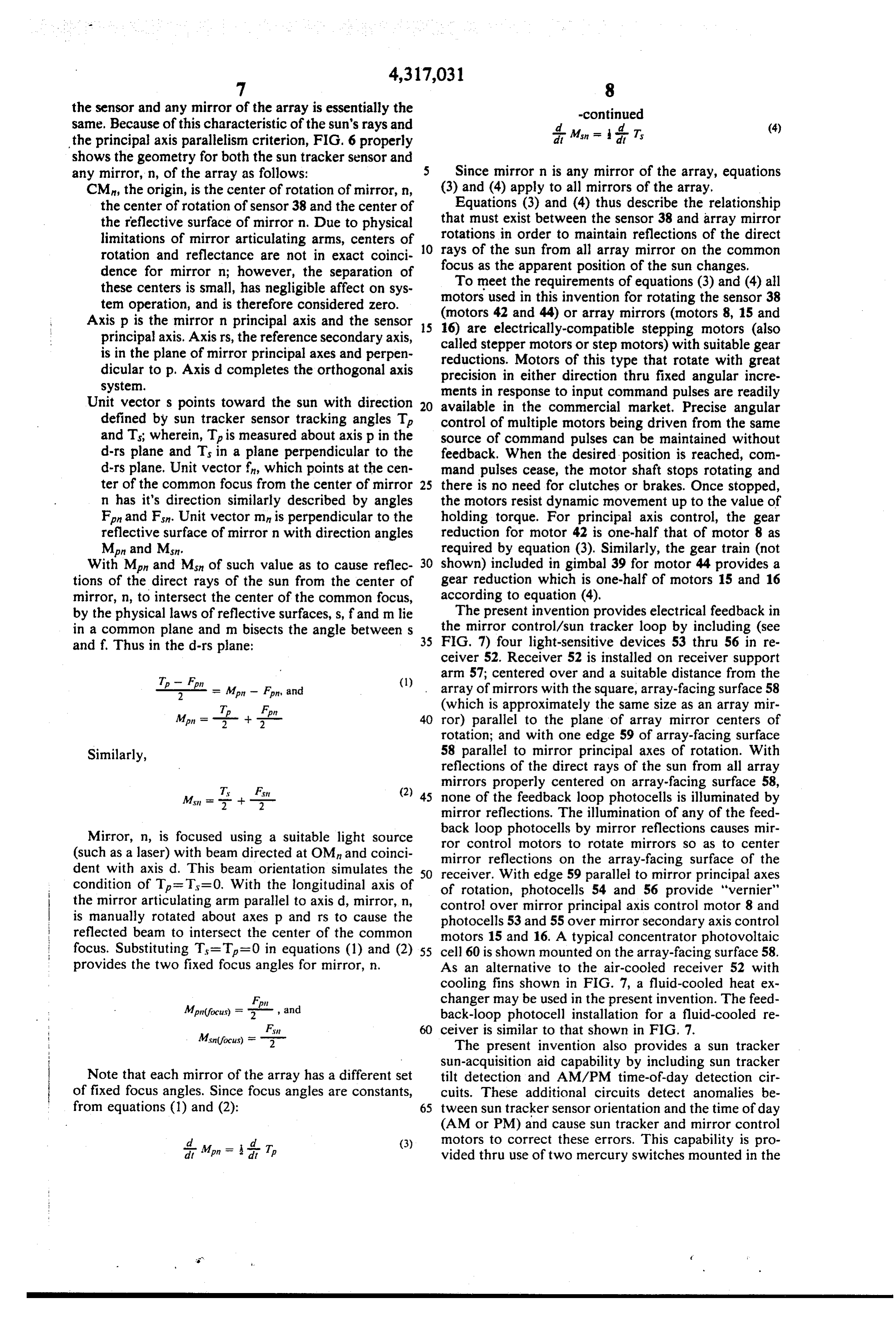
the sensor and any mirror of the array is essentially the -continued same. Because of this characteristic of the sun's rays and dd Msn - 1 a
the principal axis parallelism criterion, FIG. 6 properly shows the geometry for both the sun tracker sensor and any mirror, n, of the array as follows: 5 Since mirror n is any mirror of the array, equations CM, the origin, is the center of rotation of mirror, n, (3) and (4) apply to all mirrors of the array. the center of rotation of sensor 38 and the center of Equations (3) and (4) thus describe the relationship the reflective surface of mirror n. Due to physical that must exist between the sensor 38 and array mirror limitations of mirror articulating arms, centers of rotations in order to maintain reflections of the direct rotation and reflectance are not in exact coinci 0 focus rays of the sun from all array mirror on the common as the apparent position of the sun changes, dence for mirror n; however, the separation of To meet the requirements of equations (3) and (4) all these centers is small, has negligible affect on sys motors used in this invention for rotating the sensor 38 tem operation, and is therefore considered zero.
Axis p is the mirror n principal axis and the sensor 15 (motors
42 and 44) or array mirrors (motors 8, 15 and electrically-compatible stepping motors (also principal axis. Axis rs, the reference secondary axis, called stepper motors or step motors) with suitable gear is in the plane of mirror principal axes and perpen reductions. Motors of this type that rotate with great dicular to p. Axis d completes the orthogonal axis precision in either direction thru fixed angular incre system. ments in response to input command pulses are readily Unit vectors points toward the sun with direction available in the commercial market. Precise angular defined by sun tracker sensor tracking angles T. control of multiple motors being driven from the same and Ts; wherein, Tis measured about axis p in the source of command pulses can be maintained without d-rs plane and Ts in a plane perpendicular to the feedback. When the desired position is reached, com d-rs plane, Unit vector f, which points at the cen mand pulses cease, the motor shaft stops rotating and ter of the common focus from the center of mirror 25 there is no need for clutches or brakes. Once stopped, n has it's direction similarly described by angles the motors resist dynamic movement up to the value of Fon and Fn. Unit vector mn is perpendicular to the holding torque. For principal axis control, the gear reflective surface of mirror n with direction angles reduction for motor 42 is one-half that of motor 8 as Mpin and Ms. required by equation (3). Similarly, the gear train (not With Men and Mon of such value as to cause reflec 30 shown) included in gimbal 39 for motor 44 provides a tions of the direct rays of the sun from the center of gear reduction which is one-half of motors 15 and 16 mirror, n, to intersect the center of the common focus, according to equation (4), by the physical laws of reflective surfaces, s, fand m lie The present invention provides electrical feedback in in a common plane and m bisects the angle between s 35 the mirror control/sun tracker loop by including (see and f. Thus in the d-rs plane: FIG. 7) four light-sensitive devices 53 thru 56 in re ceiver 52. Receiver 52 is installed on receiver support
T - F. arm 57; centered over and a suitable distance from the A Pl = Mon - Fon, and (1) array of mirrors with the square, array-facing surface 58 T F (which is approximately the same size as an array mir Min = -f- + - 40 ror) parallel to the plane of array mirror centers of rotation; and with one edge 59 of array-facing surface
Similarly, 58 parallel to mirror principal axes of rotation. With reflections of the direct rays of the sun from all array
mirrors properly centered on array-facing surface 58, (2) 45 none of the feedback loop photocells is illuminated by
mirror reflections. The illumination of any of the feed back
Mirror, n, is focused using a suitable light source ror control loop photocells by mirror reflections causes mir motors to rotate mirrors so as to center (such as a laser) with beam directed at OM and coinci mirror reflections on the array-facing surface of the dent with axis d. This beam orientation simulates the 50 receiver. With edge 59 parallel to mirror principal axes condition of T = T=0. With the longitudinal axis of of rotation, photocells 54 and 56 provide "vernier" the mirror articulating arm parallel to axis d, mirror, n, control over mirror principal axis control motor 8 and is manually rotated about axes p and rs to cause the photocells 53 and 55 over mirror secondary axis control reflected beam to intersect the center of the common motors 15 and 16. A typical concentrator photovoltaic focus. Substituting T =T=0 in equations (1) and (2) 55 cell 60 is shown mounted on the array-facing surface 58. provides the two fixed focus angles for mirror, n. As an alternative to the air-cooled receiver 52 with cooling fins shown in FIG. 7, a fluid-cooled heat ex changer may be used in the present invention. The feed
Mpin(focus) = Fon - back-loop photocell installation for a fluid-cooled re ceiver is similar to that shown in FIG. 7.
The present invention also provides a sun tracker sun-acquisition aid capability by including sun tracker
Note that each mirror of the array has a different set tilt detection and AM/PM time-of-day detection cir of fixed focus angles. Since focus angles are constants, cuits. These additional circuits detect anomalies be from equations (1) and (2): 65 tween sun tracker sensor orientation and the time of day (AM or PM) and cause sun tracker and mirror control ld. Mpn = drea T (3) motors to correct these errors. This capability is pro dit vided thru use of two mercury switches mounted in the
Page 15
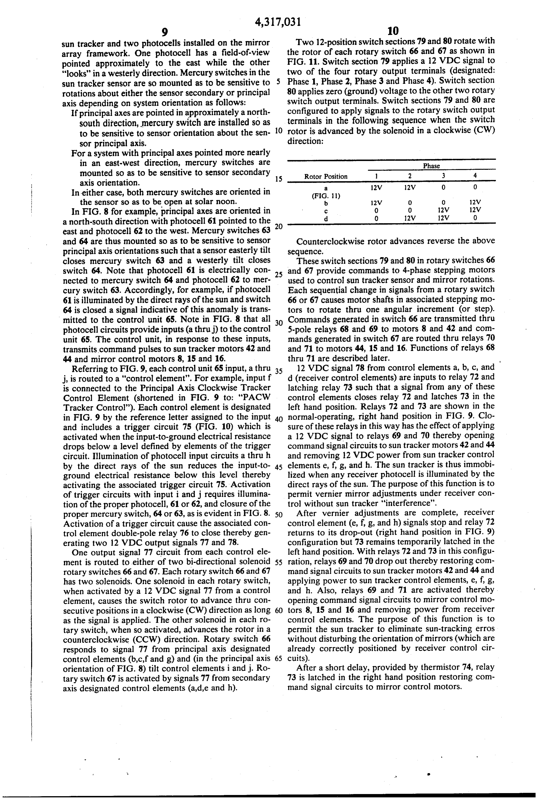
sun tracker and two photocells installed on the mirror Two 12-position switch sections 79 and 80 rotate with array framework. One photocell has a field-of-view the rotor of each rotary switch 66 and 67 as shown in pointed approximately to the east while the other FIG. 11. Switch section 79 applies a 12 VDC signal to "looks" in a westerly direction. Mercury switches in the two of the four rotary output terminals (designated: sun tracker sensor are so mounted as to be sensitive to Phase 1, Phase 2, Phase 3 and Phase 4). Switch section rotations about either the sensor secondary or principal 80 applies zero (ground) voltage to the other two rotary axis depending on system orientation as follows: switch output terminals. Switch sections 79 and 80 are If principal axes are pointed in approximately a north configured to apply signals to the rotary switch output south direction, mercury switch are installed so as 10 terminals in the following sequence when the switch to be sensitive to sensor orientation about the sen rotor is advanced by the solenoid in a clockwise (CW) sor principal axis. direction:
For a system with principal axes pointed more nearly in an east-west direction, mercury switches are Phase mounted so as to be sensitive to sensor secondary 15 Rotor Position 2 3 4 axis orientation. a 12V 12V O O In either case, both mercury switches are oriented in (FIG. 11) the sensor so as to be open at solar noon. 2V 0 0 12V In FIG. 8 for example, principal axes are oriented in d
a north-south direction with photocell 61 pointed to the 20 east and photocell 62 to the west. Mercury switches 63 and 64 are thus mounted so as to be sensitive to sensor Counterclockwise rotor advances reverse the above principal axis orientations such that a sensor easterly tilt sequence.
closes mercury switch 63 and a westerly tilt closes These switch sections 79 and 80 in rotary switches 66 switch 64. Note that photocell 61 is electrically con 25 and 67 provide commands to 4-phase stepping motors nected to mercury switch 64 and photocell 62 to mer used to control sun tracker sensor and mirror rotations. cury switch 63. Accordingly, for example, if photocell Each sequential change in signals from a rotary switch 61 is illuminated by the direct rays of the sun and switch 66 or 67 causes motor shafts in associated stepping mo 64 is closed a signal indicative of this anomaly is trans tors to rotate thru one angular increment (or step). mitted to the control unit 65. Note in FIG. 8 that all 30 Commands generated in switch 66 are transmitted thru photocell circuits provide inputs (a thruj) to the control 5-pole relays 68 and 69 to motors 8 and 42 and com unit 65. The control unit, in response to these inputs, mands generated in switch 67 are routed thru relays 70 transmits command pulses to sun tracker motors 42 and and 71 to motors 44, 15 and 16. Functions of relays 68 44 and mirror control motors 8, 15 and 16. thru 71 are described later. Referring to FIG.9, each control unit 65 input, a thru 35 12 VDC signal 78 from control elements a, b, c, and j, is routed to a "control element". For example, input f d (receiver control elements) are inputs to relay 72 and is connected to the Principal Axis Clockwise Tracker latching relay 73 such that a signal from any of these Control Element (shortened in FIG. 9 to: "PACW control elements closes relay 72 and latches 73 in the Tracker Control'). Each control element is designated left hand position. Relays 72 and 73 are shown in the in FIG. 9 by the reference letter assigned to the input 40 normal-operating, right hand position in FIG. 9. Clo and includes a trigger circuit 75 (FIG. 10) which is sure of these relays in this way has the effect of applying activated when the input-to-ground electrical resistance a 12 VDC signal to relays 69 and 70 thereby opening drops below a level defined by elements of the trigger command signal circuits to sun tracker motors 42 and 44 circuit. Illumination of photocell input circuits a thru h and removing 12 VDC power from sun tracker control by the direct rays of the sun reduces the input-to 45 elements e, f, g, and h. The sun tracker is thus immobi ground electrical resistance below this level thereby lized when any receiver photocell is illuminated by the activating the associated trigger circuit 75. Activation direct rays of the sun. The purpose of this function is to of trigger circuits with input i and j requires illumina permit vernier mirror adjustments under receiver con tion of the proper photocell, 61 or 62, and closure of the trol without sun tracker "interference'. proper mercury switch, 64 or 63, as is evident in FIG. 8. 50 After vernier adjustments are complete, receiver Activation of a trigger circuit cause the associated con control element (e, f, g, and h) signals stop and relay 72 trol element double-pole relay 76 to close thereby gen returns to its drop-out (right hand position in FIG. 9) erating two 12 VDC output signals 77 and 78. configuration but 73 remains temporarily latched in the One output signal 77 circuit from each control ele left hand position. With relays 72 and 73 in this configu ment is routed to either of two bi-directional solenoid 55 ration, relays 69 and 70 drop out thereby restoring com rotary switches 66 and 67. Each rotary switch 66 and 67 mand signal circuits to sun tracker motors 42 and 44 and has two solenoids. One solenoid in each rotary switch, applying power to sun tracker control elements, e, f, g, when activated by a 12 VDC signal 77 from a control and h. Also, relays 69 and 71 are activated thereby element, causes the switch rotor to advance thru con opening command signal circuits to mirror control mo secutive positions in a clockwise (CW) direction as long tors 8, 15 and 16 and removing power from receiver as the signal is applied. The other solenoid in each ro control elements. The purpose of this function is to tary switch, when so activated, advances the rotor in a permit the sun tracker to eliminate sun-tracking erros counterclockwise (CCW) direction. Rotary switch 66 without disturbing the orientation of mirrors (which are responds to signal 77 from principal axis designated already correctly positioned by receiver control cir control elements (b,c,f and g) and (in the principal axis 65 cuits).
orientation of FIG. 8) tilt control elements i and j. Ro After a short delay, provided by thermistor 74, relay tary switch 67 is activated by signals 77 from secondary 73 is latched in the right hand position restoring com axis designated control elements (a,d,e and h). mand signal circuits to mirror control motors.
Page 16
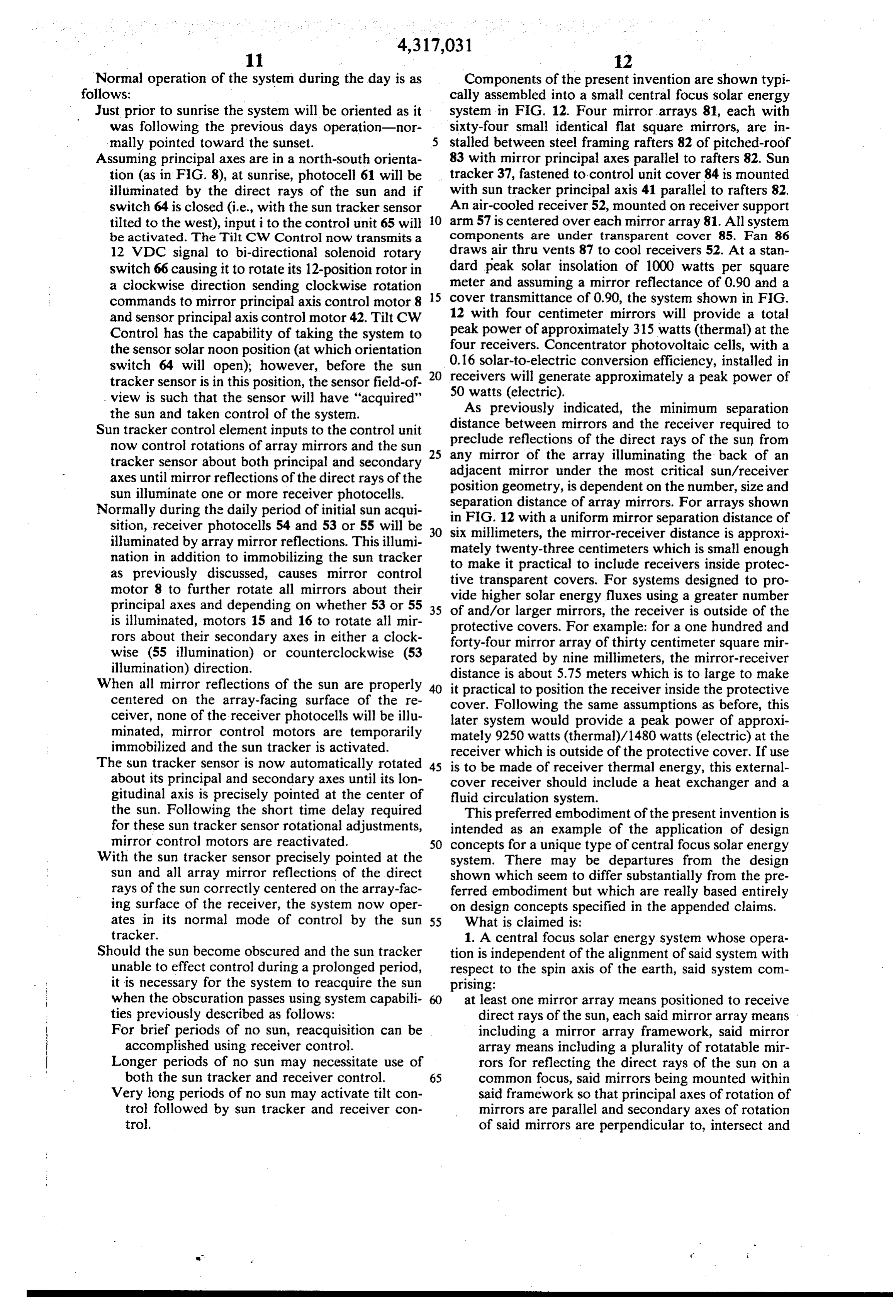
Normal operation of the system during the day is as Components of the present invention are shown typi follows: cally assembled into a small central focus solar energy Just prior to sunrise the system will be oriented as it system in FIG. 12. Four mirror arrays 81, each with was following the previous days operation-nor sixty-four small identical flat square mirrors, are in mally pointed toward the sunset. stalled between steel framing rafters 82 of pitched-roof Assuming principal axes are in a north-south orienta 83 with mirror principal axes parallel to rafters 82. Sun tion (as in FIG. 8), at sunrise, photocell 61 will be tracker 37, fastened to control unit cover 84 is mounted illuminated by the direct rays of the sun and if with sun tracker principal axis 41 parallel to rafters 82. switch 64 is closed (i.e., with the sun tracker sensor An air-cooled receiver 52, mounted on receiver support tilted to the west), input i to the control unit 65 will O arm 57 is centered over each mirror array 81. All system be activated. The Tilt CW Control now transmits a components are under transparent cover 85. Fan 86 12 VDC signal to bi-directional solenoid rotary draws air thru vents 87 to cool receivers 52. At a stan switch 66 causing it to rotate its 12-position rotor in dard peak solar insolation of 1000 watts per square a clockwise direction sending clockwise rotation 15 meter and assuming a mirror reflectance of 0.90 and a commands to mirror principal axis control motor 8 cover transmittance of 0.90, the system shown in FIG. and sensor principal axis control motor 42. Tilt CW 12 with four centimeter mirrors will provide a total Control has the capability of taking the system to peak power of approximately 315 watts (thermal) at the the sensor solar noon position (at which orientation four receivers. Concentrator photovoltaic cells, with a switch 64 will open); however, before the sun 20 0.16 solar-to-electric conversion efficiency, installed in receivers will generate approximately a peak power of tracker sensor is in this position, the sensor field-of 50 watts (electric).
view is such that the sensor will have "acquired" As previously indicated, the minimum separation the sun and taken control of the system.
Sun tracker control element inputs to the control unit distance preclude between mirrors and the receiver required to reflections of the direct rays of the sun from now control rotations of array mirrors and the sun 25 any mirror of the array illuminating the back of an tracker sensor about both principal and secondary adjacent mirror axes until mirror reflections of the direct rays of the position geometry,under the most critical sun/receiver is dependent on the number, size and sun illuminate one or more receiver photocells. separation distance of array mirrors. For arrays shown Normally during the daily period of initial sun acqui in sition, receiver photocells 54 and 53 or 55 will be 30 sixFIG. 12 with a uniform mirror separation distance of millimeters, the mirror-receiver distance is approxi illuminated by array mirror reflections. This illumi mately twenty-three centimeters which is small enough nation in addition to immobilizing the sun tracker to make it practical to as previously discussed, causes mirror control tive transparent covers.include For receivers inside protec systems designed to pro motor 8 to further rotate all mirrors about their principal axes and depending on whether 53 or 55 vide higher solar energy fluxes using a greater number 35 of and/or larger mirrors, the receiver is outside of the is illuminated, motors 15 and 16 to rotate all mir protective covers. For example: for a one hundred and rors about their secondary axes in either a clock forty-four mirror array of thirty centimeter square mir wise (55 illumination) or counterclockwise (53 rors separated by nine millimeters, the mirror-receiver illumination) direction. distance is about 5.75 meters which is to large to make When all mirror reflections of the sun are properly 40 it practical to position the receiver inside the protective centered on the array-facing surface of the re cover. Following the same assumptions as before, this ceiver, none of the receiver photocells will be illu later system would provide a peak power of approxi minated, mirror control motors are temporarily mately 9250 watts (thermal)/1480 watts (electric) at the immobilized and the sun tracker is activated. receiver which is outside of the protective cover. If use The sun tracker sensor is now automatically rotated 45 is to be made of receiver thermal energy, this external about its principal and secondary axes until its lon cover receiver should include a heat exchanger and a gitudinal axis is precisely pointed at the center of fluid circulation system.
the sun. Following the short time delay required This preferred embodiment of the present invention is for these sun tracker sensor rotational adjustments, intended as an example of the application of design mirror control motors are reactivated. 50 concepts for a unique type of central focus solar energy With the sun tracker sensor precisely pointed at the system. There may be departures from the design sun and all array mirror reflections of the direct shown which seem to differ substantially from the pre rays of the sun correctly centered on the array-fac ferred embodiment but which are really based entirely ing surface of the receiver, the system now oper on design concepts specified in the appended claims. ates in its normal mode of control by the sun 55 What is claimed is:
tracker. 1. A central focus solar energy system whose opera Should the sun become obscured and the sun tracker tion is independent of the alignment of said system with unable to effect control during a prolonged period, respect to the spin axis of the earth, said system com it is necessary for the system to reacquire the sun prising:
when the obscuration passes using system capabili at least one mirror array means positioned to receive ties previously described as follows: direct rays of the sun, each said mirror array means For brief periods of no sun, reacquisition can be including a mirror array framework, said mirror accomplished using receiver control. array means including a plurality of rotatable mir Longer periods of no sun may necessitate use of rors for reflecting the direct rays of the sun on a both the sun tracker and receiver control. 65 common focus, said mirrors being mounted within Very long periods of no sun may activate tilt con said framework so that principal axes of rotation of trol followed by sun tracker and receiver con mirrors are parallel and secondary axes of rotation trol. of said mirrors are perpendicular to, intersect and
Page 17
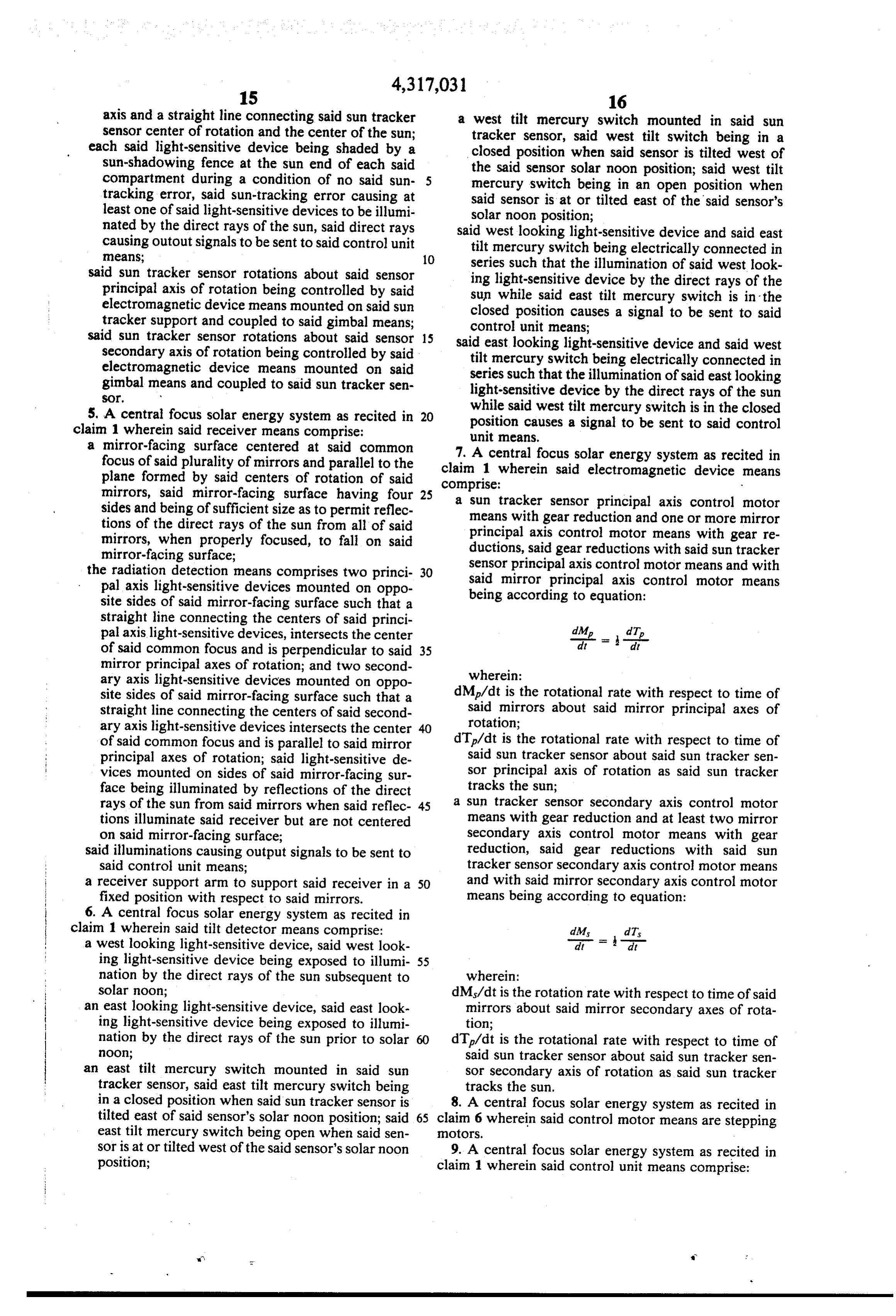
rotate about said mirror principal axes of rotation 3. A central focus solar energy system a recited in at the center of rotation for each said mirror, said claim 2 wherein said mechanical coupling means con mirror array means including electromechanical prise:
positioning means for reorienting said mirrors in 5 a plurality of mirror principal axis control brackets each pivotably mounted in said framework to ro keeping with changes in the apparent position of the sun; tate about a said mirror principal axis of rotation a control unit means connected to components of the for each bracket, at least one said mirror principal system for receiving electrical signals therefrom axis control bracket being connected to said elec and generating electrical control signals in re 10 a tromagnetic plurality of device means;
mirror articulating arms pivotably sponse thereto, said control unit being connected to mounted in each said bracket for rotation about a each said mirror array means for transmitting elec said mirror secondary axis of rotation such that said trical control signals to said electromechanical mirror secondary axes of rotation of said plurality means to cause rotations of said mirrors; of said arms are parallel and each said mirror sec a sun tracker means electrically connected to said 15 ondary axis of rotation is perpendicular to, rotates control unit that includes a sensor means for view ing the sun and generating electrical signals indica about and intersects the said mirror principal axis of rotation about which the said bracket is rotatable tive of the misalignment of said sensor with respect at the said mirror center of rotation; to the sun that are transmitted to said control unit, a mirror control bar for each said bracket to which said sun tracker including electromechanical posi 20 each said plurality of arms is pivotably coupled tioning means electrically connected to said con such that any movement or rotation of said bar trol unit for receiving control signals therefrom results in the individual and uniform rotation of all and orienting said sensor means to view the sun; said arms mounted in said bracket, said movement a receiver means electrically connected to said con of said bar in a plane including said mirror principal trol unit and mounted adjacent to said mirror array 25 axis of rotation of said bracket causing the individ means, said receiver means including a radiation ual and uniform rotation of all said arms mounted receiver surface facing said mirror array means, in said bracket about said mirror secondary axes of said receiver means including radiation detector rotation of said arms, said rotation of said bar about means mounted adjacent to said radiation receiver said mirror principal axis of rotation of said bracket surface for detecting when the center of the com 30 causing the individual and uniform rotation of all mon focus of said mirror array means is not cen said arms mounted in said brackets about said mir tered on said radiation receiver surface, said radia ror principal axis of said bracket; tion detector means generating electrical signals lever assemblies connecting at least two said bars for indicative of the direction the common focus must any said mirror array to said electromagnetic de be moved to be centered on said radiation receiver 35 vice means, said lever assemblies including said surface that are transmitted to said control unit, arms;
said control unit upon receiving a signal from said tie rods connected to corresponding ends of said bars radiation detector means transmitting electrical such that any movement or rotation of any said bar control signals to said electromechanical means to of said mirror array results in the the individual and cause rotations of said mirrors and operating to 40 uniform movement or rotation of all said bars of disable said sun tracker means to permit small cor said mirror array;
rections in orientations of said mirrors by said re mirror/mirror articulating arm coupling means ceiver means; whereby each said arm is coupled to said mirror tilt detector means electrically connected to said such that said coupled mirror and said arm are control unit and mounted in said system for detect 45 rotatable as a unit about said mirror center of rota ing large anomalies between said sun tracker orien tion.
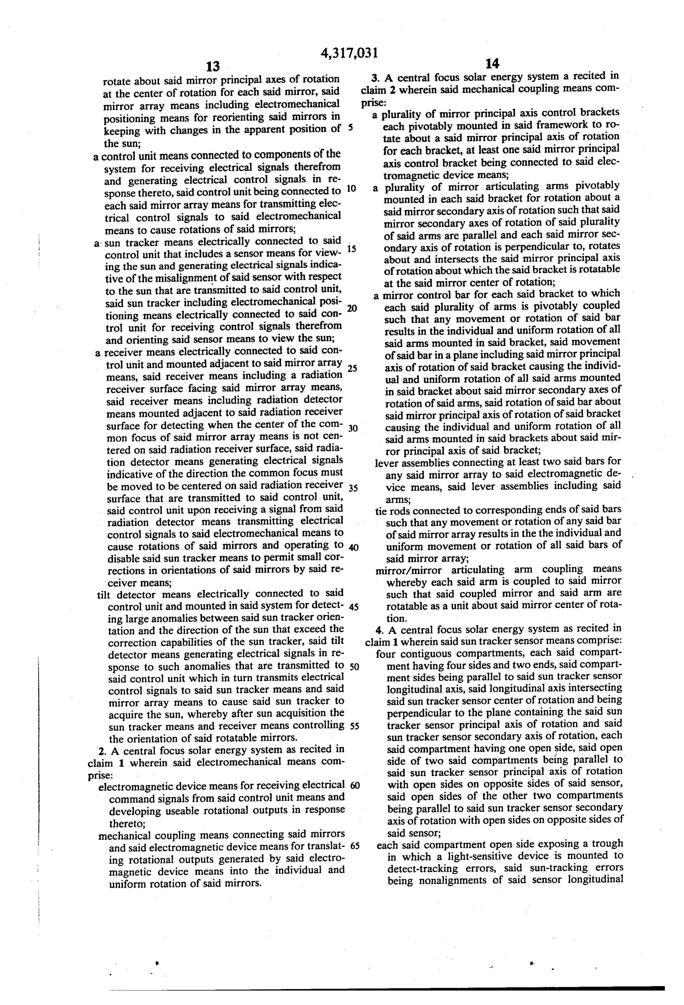
tation and the direction of the sun that exceed the 4. A central focus solar energy system as recited in correction capabilities of the sun tracker, said tilt claim 1 wherein said sun tracker sensor means comprise: detector means generating electrical signals in re four contiguous compartments, each said compart sponse to such anomalies that are transmitted to 50 ment having four sides and two ends, said compart said control unit which in turn transmits electrical ment sides being parallel to said sun tracker sensor control signals to said sun tracker means and said longitudinal axis, said longitudinal axis intersecting mirror array means to cause said sun tracker to said sun tracker sensor center of rotation and being acquire the sun, whereby after sun acquisition the perpendicular to the plane containing the said sun sun tracker means and receiver means controlling 55 tracker sensor principal axis of rotation and said the orientation of said rotatable mirrors. sun tracker sensor secondary axis of rotation, each 2. A central focus solar energy system as recited in said compartment having one open side, said open claim 1 wherein said electromechanical means com side of two said compartments being parallel to prise: said sun tracker sensor principal axis of rotation electromagnetic device means for receiving electrical with open sides on opposite sides of said sensor, command signals from said control unit means and said open sides of the other two compartments developing useable rotational outputs in response being parallel to said sun tracker sensor secondary thereto; axis of rotation with open sides on opposite sides of mechanical coupling means connecting said mirrors said sensor;
and said electromagnetic device means for translat 65 each said compartment open side exposing a trough ing rotational outputs generated by said electro in which a light-sensitive device is mounted to magnetic device means into the individual and detect-tracking errors, said sun-tracking errors uniform rotation of said mirrors. being nonalignments of said sensor longitudinal
Page 18
axis and a straight line connecting said sun tracker a west tilt mercury switch mounted in said sun sensor center of rotation and the center of the sun; tracker sensor, said west tilt switch being in a each said light-sensitive device being shaded by a closed position when said sensor is tilted west of sun-shadowing fence at the sun end of each said the said sensor solar noon position; said west tilt compartment during a condition of no said sun mercury switch being in an open position when tracking error, said sun-tracking error causing at said sensor is at or tilted east of the said sensor's least one of said light-sensitive devices to be illumi solar noon position;
nated by the direct rays of the sun, said direct rays said west looking light-sensitive device and said east causing outout signals to be sent to said control unit tilt mercury switch being electrically connected in means; 10 series such that the illumination of said west look said sun tracker sensor rotations about said sensor ing light-sensitive device by the direct rays of the principal axis of rotation being controlled by said sun while said east tilt mercury switch is in the electromagnetic device means mounted on said sun closed position causes a signal to be sent to said tracker support and coupled to said gimbal means; control unit means;
said sun tracker sensor rotations about said sensor 15 said east looking light-sensitive device and said west secondary axis of rotation being controlled by said tilt mercury switch being electrically connected in electromagnetic device means mounted on said series such that the illumination of said east looking gimbal means and coupled to said sun tracker sen light-sensitive device by the direct rays of the sun
5. A central focus solar energy system as recited in 20 while said west tilt mercury switch is in the closed claim 1 wherein said receiver means comprise: position causes a signal to be sent to said control unit means.
a mirror-facing surface centered at said common 7. A central focus solar energy system as recited in focus of said plurality of mirrors and parallel to the claim 1 wherein said electromagnetic device means plane formed by said centers of rotation of said mirrors, said mirror-facing surface having four 25 comprise:
a sun tracker sensor principal axis control
motor sides and being of sufficient size as to permit reflec means with gear reduction and one or more mirror tions of the direct rays of the sun from all of said principal axis control motor means with gear re mirrors, when properly focused, to fall on said ductions, said gear reductions with said sun tracker mirror-facing surface; sensor principal axis control motor means and with the radiation detection means comprises two princi 30 said mirror principal axis control motor means pal axis light-sensitive devices mounted on oppo being according to equation: site sides of said mirror-facing surface such that a straight line connecting the centers of said princi pal axis light-sensitive devices, intersects the center dMe
dit of said common focus and is perpendicular to said 35 mirror principal axes of rotation; and two second wherein:
ary axis light-sensitive devices mounted on oppo site sides of said mirror-facing surface such that a dMp/dt is the rotational rate with respect to time of straight line connecting the centers of said second said mirrors about said mirror principal axes of ary axis light-sensitive devices intersects the center rotation;
of said common focus and is parallel to said mirror dT/dt is the rotational rate with respect to time of principal axes of rotation; said light-sensitive de said sun tracker sensor about said sun tracker sen vices mounted on sides of said mirror-facing sur sor principal axis of rotation as said sun tracker face being illuminated by reflections of the direct tracks the sun;
rays of the sun from said mirrors when said reflec 45 a sun tracker sensor secondary axis control motor tions illuminate said receiver but are not centered means with gear reduction and at least two mirror on said mirror-facing surface; secondary axis control motor means with gear said illuminations causing output signals to be sent to reduction, said gear reductions with said sun said control unit means; tracker sensor secondary axis control motor means a receiver support arm to support said receiver in a 50 and with said mirror secondary axis control motor fixed position with respect to said mirrors. means being according to equation: 6. A central focus solar energy system as recited in claim 1 wherein said tilt detector means comprise: dM dT a west looking light-sensitive device, said west look -= - ing light-sensitive device being exposed to illumi 55 nation by the direct rays of the sun subsequent to wherein:
solar noon; dMs/dt is the rotation rate with respect to time of said an east looking light-sensitive device, said east look mirrors about said mirror secondary axes of rota ing light-sensitive device being exposed to illumi tion;
nation by the direct rays of the sun prior to solar 60 dT/dt is the rotational rate with respect to time of noon; said sun tracker sensor about said sun tracker sen an east tilt mercury switch mounted in said sun sor secondary axis of rotation as said sun tracker tracker sensor, said east tilt mercury switch being tracks the sun.
in a closed position when said sun tracker sensor is 8. A central focus solar energy system as recited in tilted east of said sensor's solar noon position; said 65 claim 6 wherein said control motor means are stepping east tilt mercury switch being open when said sen Otors.
sor is at or tilted west of the said sensor's solar noon 9. A central focus solar energy system as recited in position; claim 1 wherein said control unit means comprise:
Page 19
a principal axis control motor command source for ball socket halves being on opposite sides of said receiving electrical signals pertinent to rotational arm such that when said arm is mounted on said control about said principal axes of rotation origi bracket, the center of said ball socket is coincident nating in said sun tracker sensor, said receiver or with the associated said mirror center of rotation, said tilt detector and transmitting appropriate elec and a straight line drawn thru centers of ball reces trical command signals to said sun tracker sensor ses of said ball socket halves is conincident with the principal axis control motor and said mirror princi associated mirror principal axis of rotation; a round pal axis control motor or motors; hole thru said ball socket halves thru which a ma a secondary axis control motor command source for chine screw may be inserted for purposes of draw receiving electrical signal pertinent to rotational O ing said ball socket halves more closely together, control about said secondary axes of rotation origi said hole being at sufficient distance from the cen nating in said sun tracker sensor, said receiver or ter of said ball socket as to permit rotational move said tilt detector and transmitting appropriate elec ment of a ball of size to correspond to size of said trical command signals to said sun tracker sensor 15 ball socket, said hole being parallel to said mirror secondary axis control motor and said mirror sec principal axis of rotation with said arm mounted in ondary axis control motors; said bracket; a second round hole near the base of a capability to immobilize said sun tracker sensor said arm, said hole axis being parallel to said sec when any said receiver light-sensitive device is ondary axes shafts such that a machine screw in illuminated by reflections of the direct rays of the 20 serted thru corresponding holes in said mirror con sun by said mirrors, said sun tracker sensor being trol bar and said hole is said arm pivotably couples reactivated and said mirrors being immobilized said arm and said bar;
when said receiver light-sensitive devices are no a mirror focusing ball assembly with ball of size to fit longer so illustrated, said mirrors remaining immo into said ball socket, said mirror focusing ball as bilized for a period of time of sufficient duration to 25 sembly including a mirror mounting plate, said permit said sun tracker sensor to automatically mirror mounting plate being affixed to the back of eliminate said sun-tracking errors. said mirror; said arm and said mirror being loosely 10. A central focus solar energy system as recited in coupled by inserting ball in said ball socket, said claim3 wherein said mirror/mirror articulating arm cou mirror attached to said mirror focusing ball assem pling means comprise: bly being manually adjutable for focusing of said mirror articulating arms each comprising: two sec 30 mirror by rotating said mirror focusing ball assen ondary shafts for pivotably mounting said arm on bly in said ball socket;
said mirror principal axis control bracket, the axis a machine screw with locking nut, said machine of said shafts, when said arm is mounted on said screw being inserted in said hole thru ball socket bracket, being aligned with the associated said halves, said nut being tightened following mirror mirror secondary axis of rotation; a ball socket 35 focusing to prevent said mirror focusing ball as consisting of two ball socket halves, said ball sembly from rotating in said ball socket.
socket being located between said shafts with said
Provenance
- Collection
- Cited prior art
- Original PDF
- patentimages.storage.googleapis.com →
- Filed
- 1980-06-20
- Pages
- 19
- Method
- pdftotext (the PDF's own text layer) + pdftoppm 300dpi page scans
- Source
- Google Patents bibliographic record
- Granted
- 1982-02-23
- Inventors
- Max Findell
- Transcribed from
- patentimages.storage.googleapis.com →