patent · US3689931
Centrifugal pumps
5 September 1972
Page 1 — bibliographic record
United States Patent 15) 3,689,931 Fortis (45) Sept. 5, 1972
(54) CENTRIFUGAL PUMPS 3,187,191
6/1965 Baggs. . . . . . . . . . . . . . . . . . . . 45/202
72) Inventor: Luis R. Pagan Fortis, 1 12 Whitley
Drive, Norristown, Pa. 1940 FOREIGN PATENTS OR APPLICATIONS
(22 Filed: May 19, 1971 103,660 7|1926 Austria..................... 41.614 (21) Appl. No.: 144,983 Primary Examiner-Henry F. Raduazo
52 U.S. Cl................... ........................415/206 51 Int. Cl............................... F03b1/04, 1d 1/36 The invention related to a self-priming rotodynamic 58 Field of Search............ 415.1202,213, 206, 204, centrifugal pump and more particular to the novel 41614; 91/498 vertically split casing, the cylindrical peripheral closing ring and novel impeller embodying a fluted 56) References Cited S. conical impylsor planetary disc and spheres or "plan ets' which also are the main impeller support and ball
UNITED STATES PATENTS bearings, the vertical 'o' rings and annular gasket seals solution to expansion and contraction and the 2,532,899 12/1950 Dubost................. ...41614 recirculation passage and air passage ports for the 3,037,488 6/1962 Barrett.......... . . . . . . . . 911498 priming cycle.
3 Claims, 9 Drawing Figures
Page 2
Drawing sheet — no readable text.
Page 3
Drawing sheet — no readable text.
Page 4
Drawing sheet — no readable text.
Page 5
Drawing sheet — no readable text.
Page 6
BRIEF SUMMARY OF THE INVENTION are shown in the drawings forms which are presently preferred; it being understood however, that this
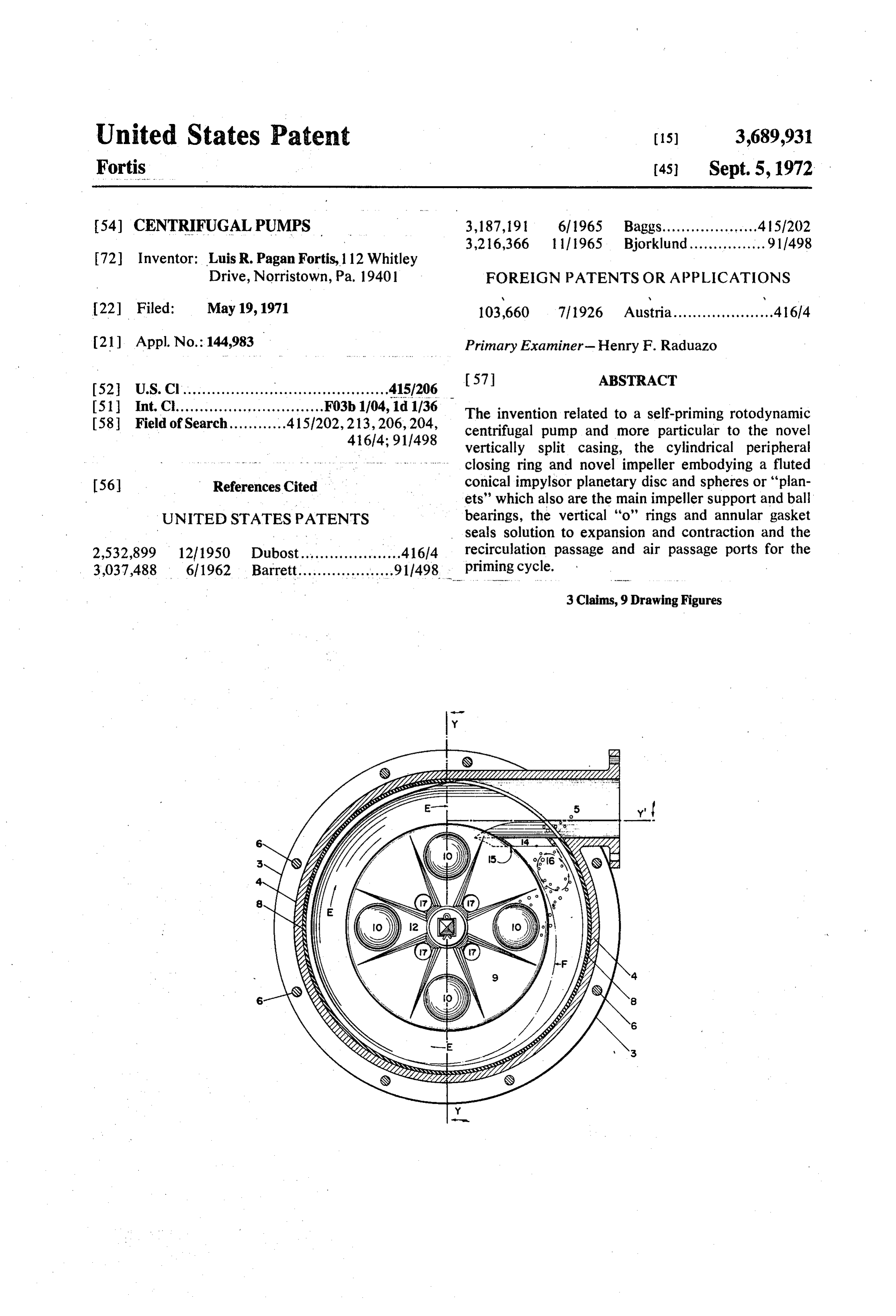
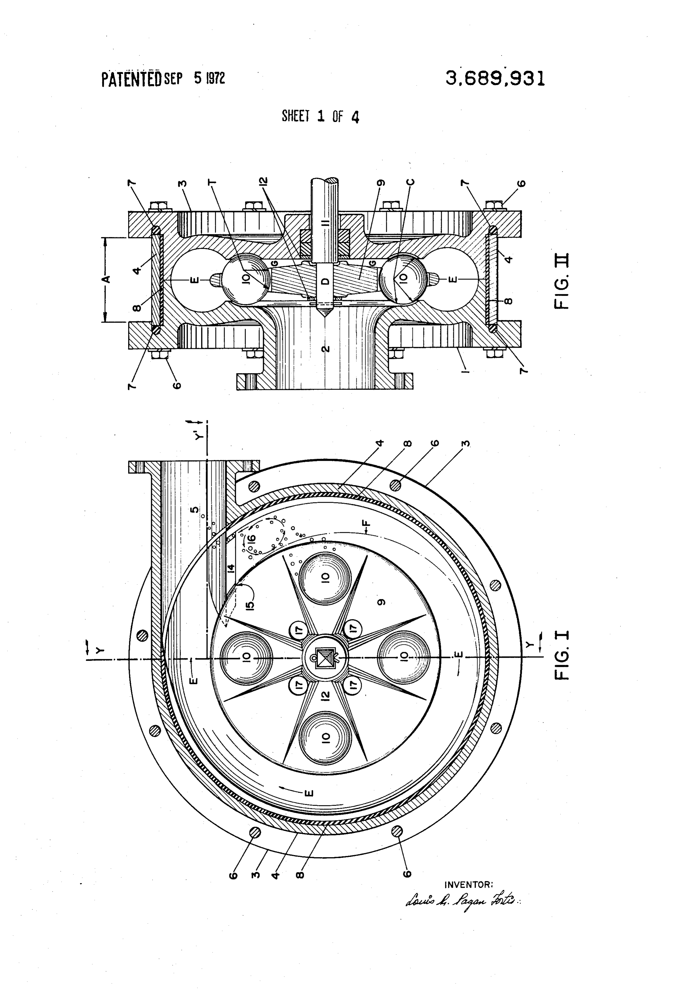
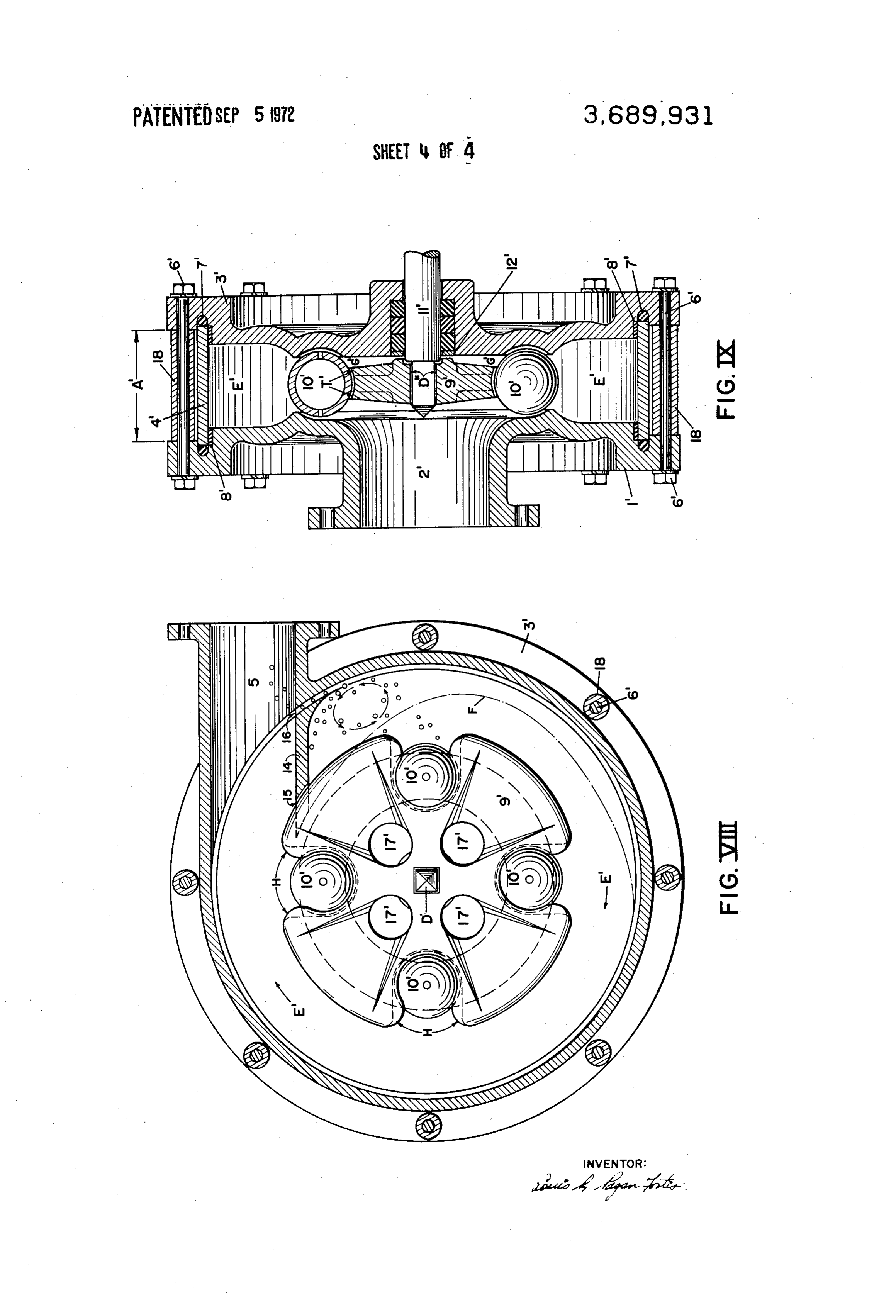
Briefly described, a preferred embodiment of the invention is not limited to the precise arrangements invention consists of a vertically split casing with and instrumentalities shown. split integral cutwater wall and a cylindrical peripheral FIG. I shows preferred embodiment of the inven closing ring embodying a discharge outlet; said cylin tion with outboard casing removed and the cylindrical drical closing ring and the split casings bounded to closing ring sectioned.
gether by through bolts and housing a rotable diffuser FIG. II shows section y-y generally following or impeller. Said diffuser or impeller consisting of a 10 lines of section y-y in FIGS. I and VI, spheres symmetrically perforated, fluted impulsor planetary are not sectioned.
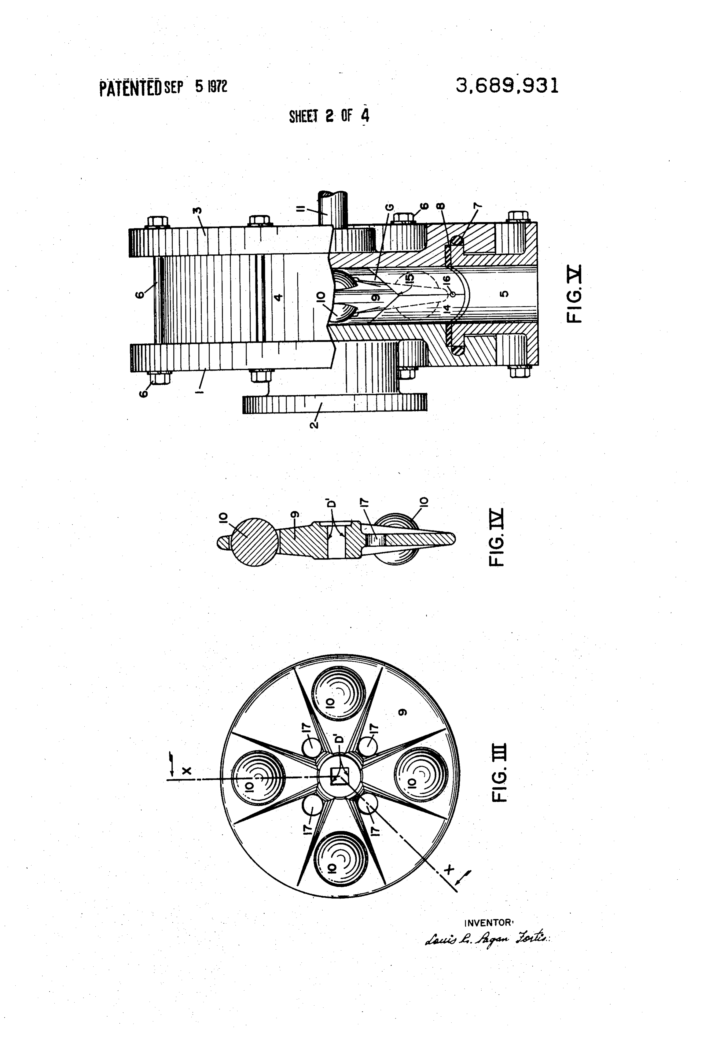
disc loosely coupled to a rotable axle and having a FIG. I shows side view of the impeller. plurality of radically opposed "captive' spheres or FIG. IV shows section through fluted and solid planets; said spheres or planets basically substituting portions of impulsor disc, basically following line the blades or vanes in prior art impellers. 15 x-x in FIG. III.
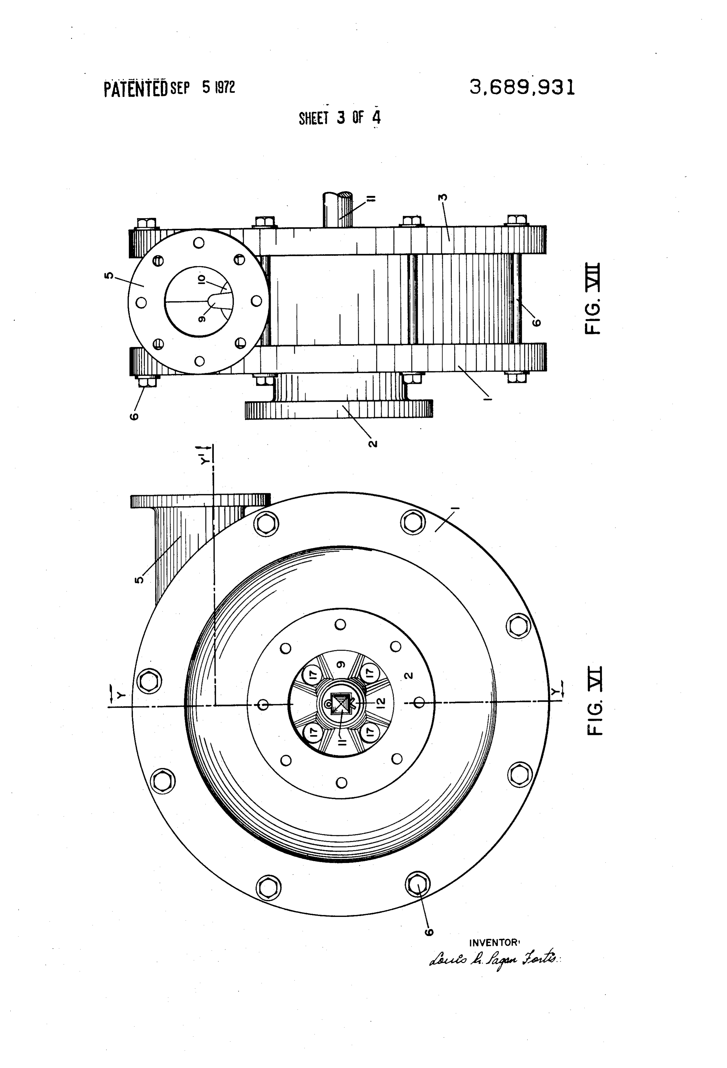
In operation, the fluted impulsor disc while rotating FIG. V shows cut y-y basically following lines causes the spheres to displace gyrating in a circular y-y1 in FIGS. I and VI.
path as described and restricted by the guiding cheek FIG. VI shows exterior sideview of device facing races provided for in the inside face of the casing. the intake port.
Thus mechanism is provided whereby a static 20 FIG. VII shows exterior edge view of device priming residual or added liquid at the bottom of the facing discharge port. . . . . . . ... casing is impacted by the spheres, rotated at high FIGS. VIII and IX shows modified embodiment of velocity and radially diffused by centrifugal force the device.
into a uniform restricted annular chamber. A sub stantial amount of this priming liquid is forced under 25 DETAILED DESCRIPTION OF THE the cutwater wall where air is strained from the INVENTION liquid by scrubbing and allowed to escape to discharge atmospheric pressure through a port provided for Referring generally to the drawings wherein the at the root of the cutwater wall. Thus air strained showings are for the purpose of illustrating a pre liquid is recirculated to the bottom of the casing to ferred embodiment of the invention only and not for reinforce the already established priming cycle. the purpose of limiting same, the figures marked in Action as described above creates pressure differ Roman numbers show an axial feed, unmounted ential at the face and behind the impeller causing addi self-priming rotodynamic planetary centrifugal pump tional liquid to be led from the intake line to the center 35 of undefined size and mass. and through the impulsor disc where the axially flow In more detail, the device in a preferred embodi ing liquid is set in fast rotation and outwardly diffused ment, consists of a vertically split casing of new design at high velocity to a restricted uniform annular cham in which the outboard casing 1 embodying the intake ber by centrifugal force absorbed from the fluted port 2 and the inboard casing 3 are separated by a impulsor disc and the rotating, gyrating spheres. 40 cylindrical peripheral closing ring 4 embodying a The liquid, compelled to flow along the restricted tangential discharge port 5. A plurality of through uniform annular passage by the peripheral tangential bolts 6 holds the entire housing together at a minimum vector of the impeller, is given initial direction by a peripheral constant designated separation A. Two self-adjusting "liquid volute' created under the cut "O' rings 7 facing and following the cylindrical water wall. Upon completion of a peripheral travel 45 closing ring 4 edges prevent leaks and act as lateral along the annular passage, the flow is then intercepted expansion cushions. A peripheral cylindrical flat by the cutwater wall and directed to a tangential dis sealer gasket 8 that can be permanently adhered to charge port. the closing ring 4 is provided for vertical expansion. The novel impeller housed by the casing consists of
OBJECTS OF THE INVENTION 50 two parts: a fluted planetary disc 9 and a plurality of The principal object of the invention is to provide Spheres or planets 10 radially opposed and nested a new and highly improved centrifugal pump which is in holes generally in the periphery of the disc. The planets 10 are kept in a restricted path by the guiding simple in construction, economical to manufacture, circular cheek races C provided for in the inside face economical to operate and which strongly and 55 definitely upgrades the inherent low efficiency of of the casings.
prior art. The rotable axle 11 is loosely coupled to the im A principal object is to offer designers, manufac axle anddisca 9corresponding pulsor by engaging a square portion D of the turers and users freedom from the highly restrictive center of the impulsor discsquare 9. This opening D in the articulated condi manufacturing, assembly and operational tolerances 60 tion allows the impulsor disc 9 lateral oscillation or of today's art.
Further objects are: elimination of "apply lubrica movement along the tangential contact surface market tion' as we know, simplified seals, reduced opera "T" tween in FIG. I. A designated clearance or play be the impulsor disc hub and washers 12 allows :
tional friction, turbulance, slippage and axial stresses.- 65 but limits such lateral motion that in prior art is BRIEF DESCRIPTION OF SEVERAL VIEWS directly transferred to the axle. OF THE DRAWINGS Axial bearing, as contemplated by the invention, will also be eliminated by providing a liquid laminar
For the purpose of illustrating the invention, there support cushion in all contact points between axle
Page 7
11, impulsor disc 9, spheres 10 and circular guiding this novel arrangement not only in the pumping cheek races "C". Thus restricted, articulated and sequence, but also in the priming cycle. highly lubricated arrangement is provided, capable Further development and experience with the of adjusting to deviations due to internal or external invention will dictate the most efficient masses, operational stresses resulting from impact, friction 5 tolerances and ratios requirements to meet all opera or wear. In addition, passthrough ports 17 in the tional loads and velocities. impulsor disc allows hydraulic pressurization of the While this invention has been described with inboard chamber G adding shock absorbing dynamic reference to the preferred embodiment or embodi stability to the impeller. This flexible, self-lubricating, 10 ments of the invention, obviously modifications and statically and dynamically balanced mechanical alterations will occur to others upon reading and train permits, as shown, the elimination of unwanted, understanding of these specifications and drawings. destructive axial thrust and axial bearing stresses It is my intention to include such modifications and usually inherent in prior art. The final recipient of alterations insofar as they come within the scope of the stresses is the liquid being pumped. 15 the appended claims except where limited by prior art. In operation, the fluted impulsor disc 9 while Having thus described my invention patent letters rotating causes the spheres 10 to displace gyrating are claimed for:
in a circular path as described and restricted by the 1. A self-priming axially fed, rotodynamic planetary guiding cheek races C provided for in the inside face centrifugal pump comprising - of the casing. 20 a vertically split casing consisting of an inboard Thus mechanism is provided whereby a static casing embodying an integral half of the cutwater priming residual or added liquid at the bottom of the wall, an outboard casing having an axially extend casing is impacted by the spheres 10, rotated at high in fluid inlet and an integrated matching half of velocity and radially diffused by centrifugal force the cutwater wall, both casings having circular into a uniform restricted annular chamber E. A 25 guiding cheek concave races in the inside face, substantial amount of this priming liquid is forced a cylindrical peripheral closing ring embodying the under the cutwater wall 14 through set back dents 15 discharge outlet 5, where air is strained from the liquid by scrubbing a pair of "O" rings facing and following cylindrical and allowed to escape to discharge atmospheric closing ring and a flat gasket seal between closing pressure through a port 16 provided for at the root 30 ring and the casing, of the cutwater wall 14. Thus air strained liquid is a rotable impeller within the casing consisting of a recirculated to the bottom of the casing to reinforce radially fluted conical impulsor disc having a the already established priming cycle. plurality of radially opposed through ports, a Action as described above creates pressure coupling square center bore and a plurality of differential at the face and behind the impeller causing radially opposed round holes nesting same additional liquid to be led from the intake line to the number of spheres having substantially the same center and through the impulsor disc 9 where the diameter as said round holes, a uniform annular axially flowing liquid is set in fast rotation and out discharge chamber as formed by the split casings, wardly diffused at high velocity to a restricted uni- 40 obstructed by an integral cutwater wall having a form annular chamber E by centrifugal force absorbed set back recirculation dent at the lip joint and an from the fluted impulsor disc 9 and the rotating, air escape port at the intersection with the cylin gyrating spheres 10. drical closing ring in the neighborhood of the The liquid, compelled to flow along the restricted discharge outlet, uniform annular passage E by the peripheral tangential 45 a rotable cylindrical axle with a square portion at vector of the impeller, is given initial direction by a the inside part of the axle where it freely couples the impulsor disc, self-adjusting "liquid volute' F created under the a plurality of continuous through bolts, pressure cutwater wall 14. Upon completion of a peripheral washers and nuts holding the entire housing travel along the annular passage E the flow is then together.
intercepted by the cutwater wall 14 and directed to a 50 2. A self-priming, axial feed, roto-dynamic plane tangential discharge port 5. tary centrifugal pump as set forth in claim 1 wherein Further particulars of the invention points to a low said radially fluted impulsor disk 9' has radially power requirement characteristic, largely due to opposed peripheral dents 4 with concave seats T. minimum operational friction and slippage, but 55 nesting said spheres 10", said impulsor disk having mostly, theoretically, to the advantageous mechanical means to permit the disk to oscillate laterally and radii ratio between spheres 10 and the impulsor 9 vertically with restricted designated clearance or as translated to a full circumferential sphere gyration play with the concave seats T', said peripheral and a full sphere rotation along the guiding cheek indents 4 and said guiding cheek races C' in the inside aC. 60 of said casings, thus permitting the removal and re Thus assuming a two-inch spherical circumference placement of said axle by simply pulling the axle in the sphere or planet and an eight-inch circular from the power connected side without disturbing cheek race travel or full rotation, the theoretical the assembled arrangement of the pump parts. ratio will be four. Meaning that for every rotation 3. A self-priming axially feed, rotodynamic plane of the impulsor disc 9 the sphere will gyrate or spin 65 tary centrifugal pump of claim 1 wherein said plurality four times. Logically a 1000 RPM on the impulsor of spheres are hollow, said spheres having not less disc will produce 4000 GYPM (gyrations per minute) than two coplanar diametrically opposed ports for in the spheres. Needless to point the importance of liquid to penetrate and be retained thereby in the
Page 8
hollow chambers of said spheres whereby said re tained liquid will be discharged upon demand on the reduction of pumped liquid in an emergency to safely continue lubrication of the moving parts of the pump
Provenance
- Collection
- Cited prior art
- Original PDF
- patentimages.storage.googleapis.com →
- Filed
- 1971-05-19
- Pages
- 8
- Method
- pdftotext (the PDF's own text layer) + pdftoppm 300dpi page scans
- Source
- Google Patents bibliographic record
- Granted
- 1972-09-05
- Inventors
- Luis R Pagan Fortis
- Transcribed from
- patentimages.storage.googleapis.com →