patent · US4284899
Gravity fed power generator
18 August 1981
Page 1 — bibliographic record
United States Patent (19) (11) 4,284,899 Bendiks 45) Aug. 18, 1981 54 GRAVITY FED POWER GENERATOR 56 References Cited
(76) Inventor: Donald J. Bendiks, 1020 Water St., 3,484,617 12/1969 Winsel .................................... 290/44 New Buffalo, Mich. 49117 4,075,838 2/1978 Pelin ................................ 290/1 RX 4,095,118 6/1978 Rathbun ............................ 290/52 X 21 Appl. No.: 90,673 Primary Examiner-J. V. Truhe Assistant Examiner-W. E. Duncanson, Jr.
22 Filed: Nov. 2, 1979 57 ABSTRACT A power supply generator system including a fuel cell, an impulse turbine, an electrolyzer and a regulator bat
Related U.S. Application Data tery which serve to supply each other and a consumer with energy. The fuel cell combines hydrogen and oxy 63 Situation of Ser. No. 18,605, Mar. 8, 1979, aban- gen to produce electricity and water. The fuel cell is located at a distance above the impulse turbine and the water from the fuel cell falls to activate the turbine 51) Int. Cl.......................... FO3B 13/06; HO2K7/18 which produces energy. The water then flows to the 52 U.S.C. ..................................... 290/1 R; 290/52; electrolyzer to be separated into hydrogen and oxygen
58 Field of Search ..................... 290/1, 2, 43, 44, 52, 290/54, 55 6 Claims, 6 Drawing Figures
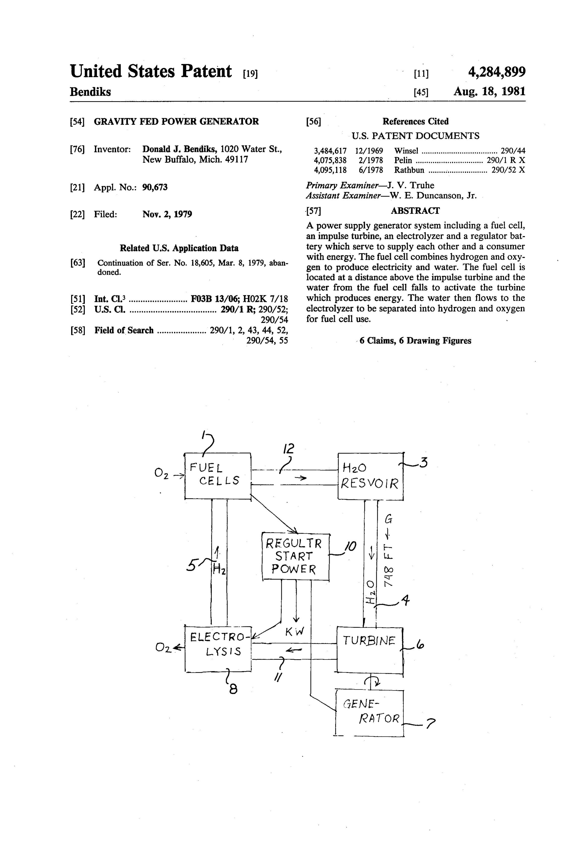
o, FEL
CEL LS
H2O VOR 3
5 YH POWER e
(ENE
Page 2
Drawing sheet — no readable text.
Page 3
Drawing sheet — no readable text.
Page 4
Drawing sheet — no readable text.
Page 5
Drawing sheet — no readable text.
Page 6
nected generator 7. Generator 7 produces energy which
GRAVITY FED POWER GENERATOR is transferred to
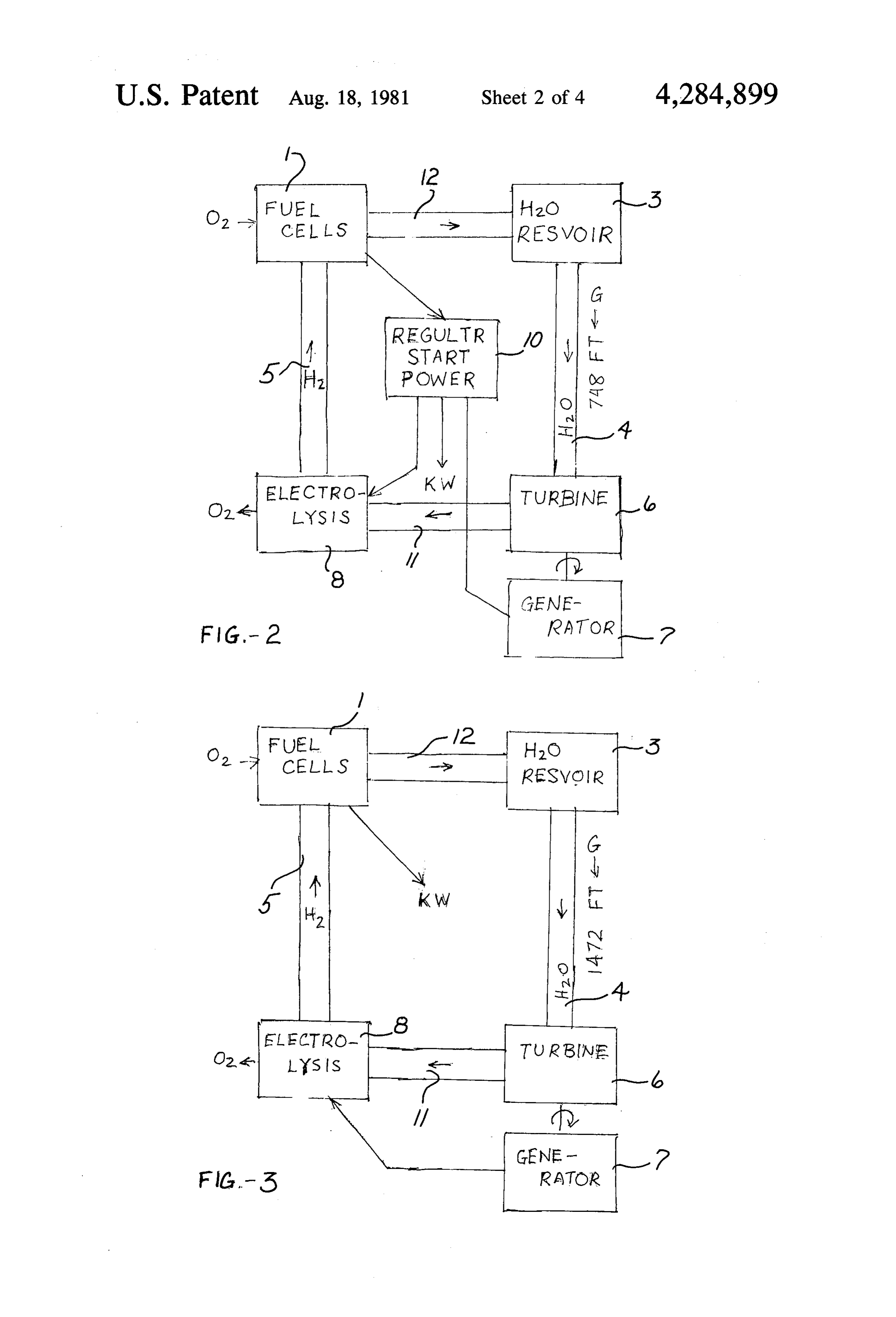
Upon exitig turbine 6, the water is routed to electro
SUMMARY OF THE INVENTION lyzer 8 through conduit 11. Within electrolyzer 8, water is separated into its components, oxygen and hydrogen.
This application is a continuation of application Ser. 5 The
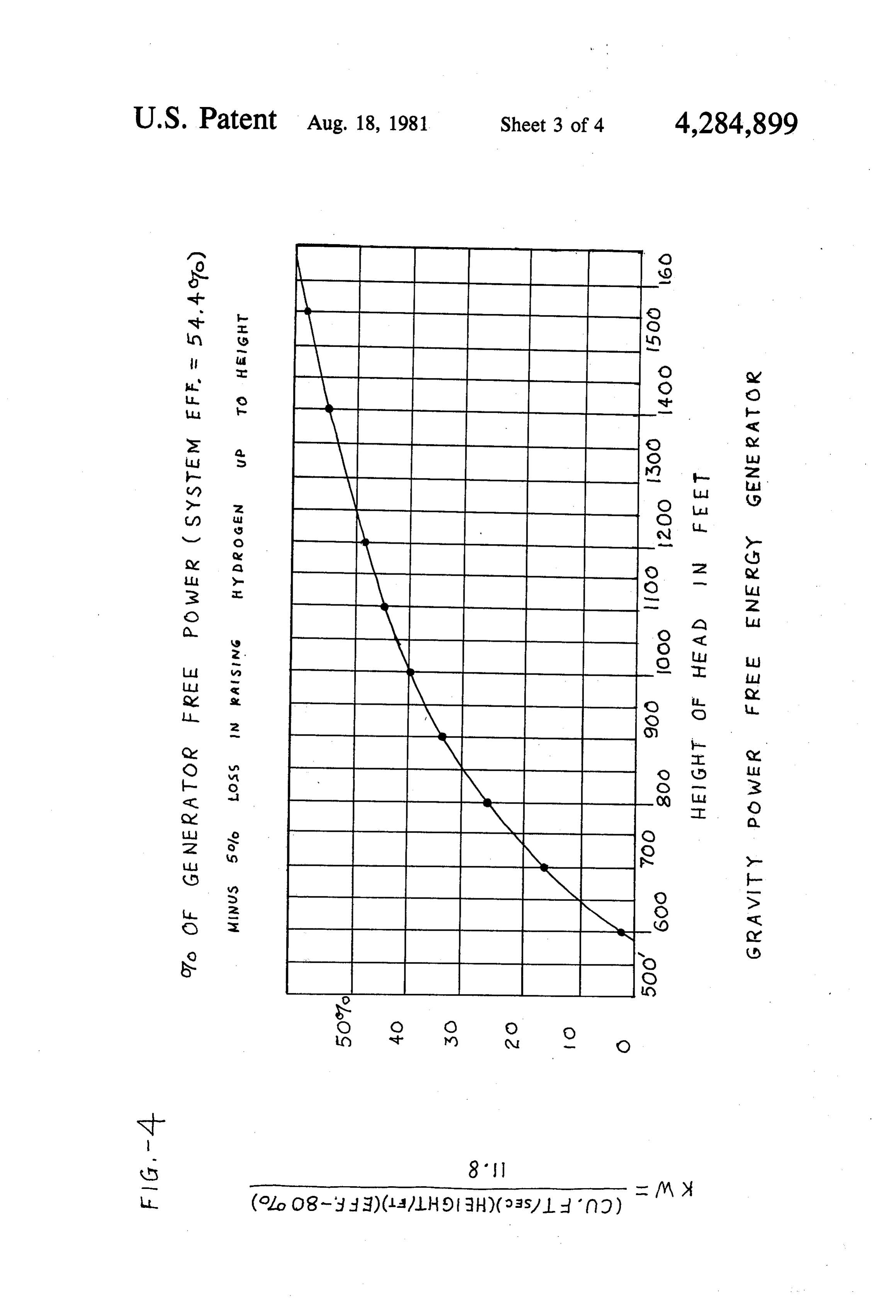
No. 018,605, filed Mar. 8, 1979 now abandoned. energy required for electrolyzer 8 comes from This invention relates to a power supply generator generator 7 in FIG. 3 and from the generator and a system having in combination a fuel cell, an impulse regulator or storage battery 10 in FIG. 2. If the height of water reservoir tank 3 is sufficient, turbine generator and an electrolyzer. 10 then supplemental power will not be required from The combination of these units into one system repre storage battery 10 used in FIG. 2. With water reservoir sents an innovation in power generators. The individual tank 3 located at 1472 feet above turbine 6, generator 7 units act synergistically to produce fuel and/or energy is capable to feed other components as well as produce energy electrolyzerof8.producing FIG. 4 sufficient power to operate displays the increase in the through the combination of hydrogen and oxygen and, 15 amount of power produced as the height also, has water as a by-product. With the fuel cell lo voir tank 3 above turbine 6 increases. of water reser cated at an appropriate height above the impuse turbine, Electrolyzer 8 has a vent 9 (see FIG. 1) through the falling water from the fuel cells possesses sufficient which kinetic energy to activate the turbine. The turbine pro sphere. the oxygen produced is released to the atmo Hydrogen produced through the electrolysis is duces electricity and as the water exits the turbine it 20 flows to the electrolyzer where it is separated into hy pumped up conduit 5 to fuel cell 1. drogen and oxygen with the hydrogen being produced onFuel cell 1 is an ion transfer cell, similar to those used space flights. An example of such a fuel cell is the for use in the fuel cell.
The fuel cell, in turn, produces electricity for use in page 533 of Fuelhydrogen-oxygen
fuel cell as shown on
Electrochemistry by Bock running the electrolyzer with any excess being stored in 25 ris and Srinivasan. Within fuel cell 1, hydrogen is re batteries for future use within the system or by a con combined with oxygen which has been introduced to
the fuel cell is atmospheric oxygen through
Accordingly, it is the object of this invention to pro vent 2. By means of ion transfer the hydrogen and oxy air intake vide an economical means for producing energy. gen are recombined to produce electricity and water. Another object of this invention is to combine the 30 The water produced flows through conduit 12 to water separate units of fuel cell, impulse turbine and electro tank 3 to begin the cycle anew. The electricity pro lyzer into an efficient energy producing system. duced by fuel cell 1 is directed, in FIG. 2, to regulator Still another object of this invention is to provide a storage battery 10 where it is available for use when new source of electrical energy. needed for consumer use or as a power additive for the Other objects of this invention will be apparent upon 35 electrolyzer 8. THe power stored in the regulator-stor a reading of the following description. age battery 10 may also be used in the electrolyzer 8 to BRIEF DESCRIPTION OF THE DRAWINGS restart the system after a shut down. FIGS. 5 and 6 depict different embodiments of the
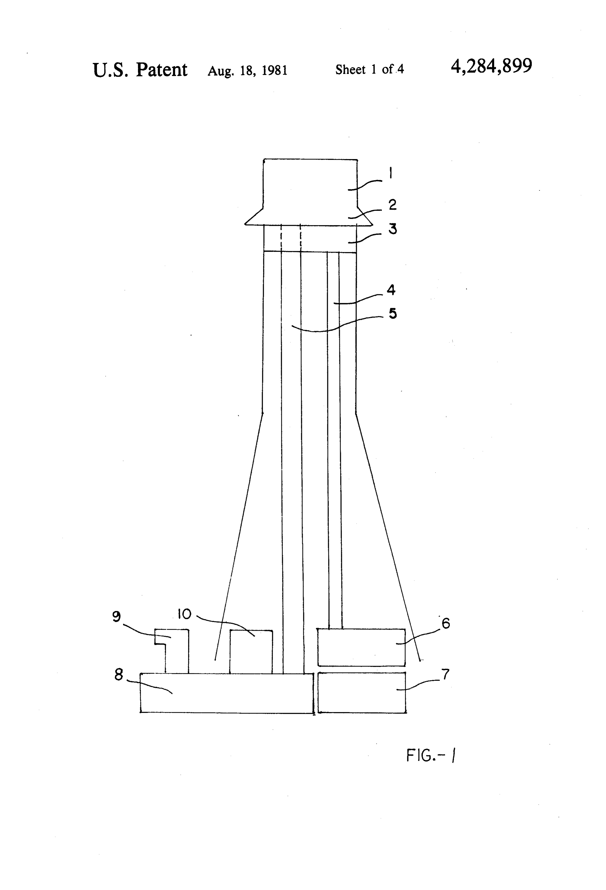
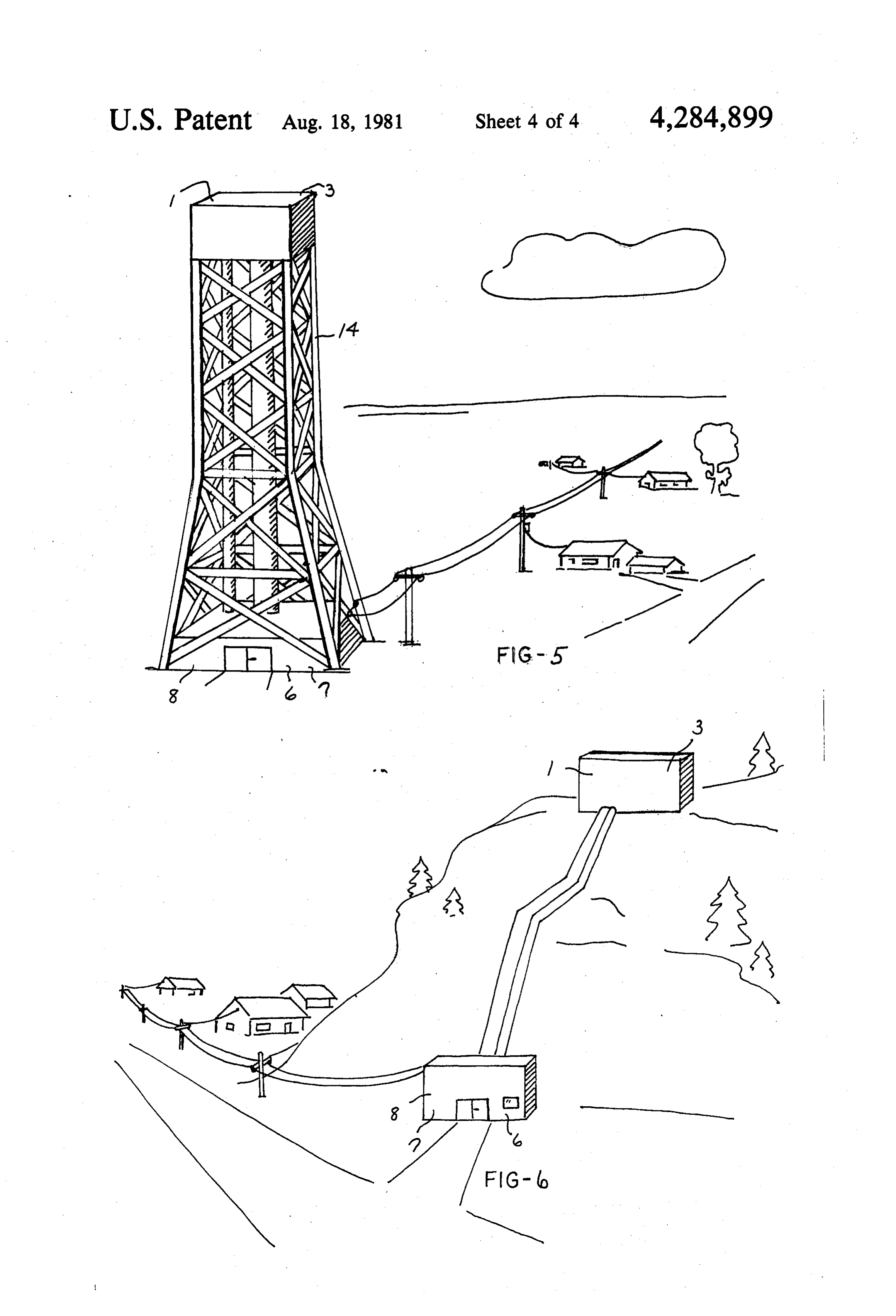
FIG. 1 shows a diagrammatic elevational view of the system to accommodate the site of construction. As system. seen in FIG. 5, a tower 14 can be utilized to house the FIG. 2 is a schematic of the cycle of the energy pro fuel cell and water tank when the land is flat. On the duction for the system. other hand, if the area is mountainous or hilly, the fuel FIG. 3 is a schematic of another cycle of energy cell and water tank can be located at the top or at any production for the system. desired point up the side of the hill, as shown in FIG. 6. FIG. 4 is a graph depicting the production of energy 45 The projected maximum combined efficiency of this using the invention. system is about 50%. Therefore, water reservoir tank 3 FIG. 5 is a perspective view of the system in use. is adapted to periodically release a predetermined FIG. 6 is a perspective view of another embodiment amount of water into the system. By doing this, water of the system in use. need only be added to the reservoir periodically rather 50 than continuously for replenishment purposes.
DESCRIPTION OF THE PREFERRED
EMBODIMENTS It is to be understood that the invention is not to be limited to the details above given but may be modified
Referring to the drawings, FIG. 1 shows the overall within the scope of the appended claims. arrangement of the components of the invention. The What I claim is:
system includes a fuel cell 1, impulse turbine 6, genera 55 1. A power supply generator system comprising in tor 7, an electrolyzer 8 and storage battery 10. These combination a fuel cell within which hydrogen gas and components functionally combine to produce and store oxygen are combined to produce water and electrical energy from an abundant fuel source, water. energy, an impulse turbine, said fuel cell being located Referring to FIGS. 2 and 3, following the water above said turbine, said turbine including impeller through a cycle and beginning at water reservoir tank 3, 60 means, conduit means extending downwardly from said the water possesses potential energy due to the height of fuel cells to said turbine for conducting by gravitational the water reservoir tank. fall the water produced by said fuel cell to said turbine Upon release from water reservoir tank 3, the water impeller means to cause rotation of the impeller means falls by gravity down conduit 4 to turbine 6. During its for providing electricity upon rotation of said impeller descent, the potential energy of the water at the top of 65 means, an electrolyzer means for producing hydrogen conduit 4 is changed to kinetic energy. The kinetic gas by the electrolysis of water, conduit means connect energy of the water turns the impellers of turbine 6. The ing said turbine with said electrolyzer means for con rotation of turbine 6 in turn causes rotation of con ducting water from said turbine impeller means to the
Page 7
3. The generator system of claim 1 and including electrolyzer means to produce hydrogen, conduit electrical energy storage means for storing the electric means connecting said electrolyzer means with said fuel ity produced by said fuel cell and said generator. 4. The generator system of claim 2 wherein said fuel cell for conducing hydrogen to the fuel cell to produce cell is located at least 748 feet above said turbine. Water. 5. The generator system of claim 1 wherein said first mentioned conduit means includes a reservoir for said 2. The generator system of claim 1 wherein the physi water, said reservoir being located above said turbine at cal location of said electrolyzer means relative to the a location wherein said water passing from the reservoir 10 to the turbine will cause rotation of said turbine impeller turbine being such that the kinetic energy of the water 6.a.S.
in said connecting conduit means when exiting said 6. The generator system of claim 1 and including a regulator means for directing energy produced in said turbine being sufficient to independently enter the elec fuel cells to said electrolyzer means.
Provenance
- Collection
- Cited prior art
- Original PDF
- patentimages.storage.googleapis.com →
- Filed
- 1979-11-02
- Pages
- 7
- Method
- pdftotext (the PDF's own text layer) + pdftoppm 300dpi page scans
- Source
- Google Patents bibliographic record
- Granted
- 1981-08-18
- Inventors
- Donald J. Bendiks
- Transcribed from
- patentimages.storage.googleapis.com →