patent · US4283588
Automatic guidance system for radiation-responsive systems
11 August 1981
Page 1 — bibliographic record
- -- m r s r. - Y - wif w rw AW
8/ M8 XR 4 283,588
United States Patent (19) 11) 4,283,588 Zitzelsberger 45) Aug. 11, 1981 54 AUTOMATIC GUIDANCE SYSTEM FOR 4,044,752 8/1977 Barak ................................... 126/425 RADATION-RESPONSIVE SYSTEMS 4,063,543 12/1977 Hedger ..... ... 126/425 4,158,356 6/1979 Wininger .............................. 126/425 75) Inventor: Helmut Zitzelsberger, Munich, Fed. Primary Examiner-Aaron Weisstuch Rep. of Germany
Attorney, Agent, or Firm-Hill, Van Santen, Steadman, 73) Assignee: Siemens Aktiengesellschaft, Berlin & Chiara & Simpson
Munich, Fed. Rep. of Germany 57) ABSTRACT (21) Appl. No.: 72,096 The invention concerns a guidance, or tracking, ar 22 Filed: Sep. 4, 1979 rangement which automatically adjusts the alignment of 30 Foreign Application Priority Data a radiation responsive system in accordance with the Sep. 27, 1978 (DE) Fed. Rep. of Germany - - - - - - 2842084 position of a movable radiation source. The arrange ment utilizes two bodies able to transmit heat expansion 51) Int. Cl. ............................................. H01L 31/00 forces into linear movements to rotate a rocker about an 52 U.S. Cl. .................................... 136/246; 126/425; axis perpendicular to the path plane of the source. The 250/203 R; 353/3 bodies are partially shaded such that exposure to the 58 Field of Search ................... 136/89 PC; 126/422, radiation source controls the extent to which the bodies 126/424, 425; 250/203 R; 353/3 rotate the rocker. Resilient support means compensate 56) References Cited the arrangement for undue forces arising from expan sions of the bodies.
3,982,526 9/1976 Barak ................................... 126/425 5 Claims, 2 Drawing Figures
Page 2
Drawing sheet — no readable text.
Page 3
tion of a movable radiation source, such as the sun, so
AUTOMATIC GUIDANCE SYSTEM FOR that the system's exposure to radiation is maintained at RADATION-RESPONSIVE SYSTEMS low angles of incidence. The inventive arrangement utilizes thermal expansion due to the heat of radiation
BACKGROUND OF THE INVENTION 5 from the source to propel the system into proper orien 1. Field of the Invention tation to the source. The invention is further arranged The invention relates to an automatic guidance ar so that undue forces do not build up and expansion rangement for a system responsive to radiation when effects due to changes in air temperature do not inter the heat radiation source is movable. fere with the guidance, or tracking, operation. O In accordance with the invention, the guidance ar 2. Description of the Prior Art
There are presently known many types of systems rangement utilizes two bodies having means able to which function in response to radiation. For example, transmit forces due to thermal expansion occurring such systems have been employed to take measurements within each of the bodies into linear, longitudinal move of or locate a heat radiation source, or to absorb or 5 ments and a rocker rotatable about an axis running reflect heat radiation, or to effect shading against a perpendicular to the path plane of a movable radiation radiation source. The degree to which the systems re source. The bodies are positioned in a spaced-apart and ceive the radiation affects the performance and exercise parallel fashion on either side of a vertical plane con of the systems' radiation-related functions. A critical taining the rotation axis such that their linear move factor in achieving efficient radiation reception is a 20 ments at one end serve to tilt the rocker about its rota system's angle of incidence to the radiation source. tion axis. The bodies are supported at their other end The angle of incidence to a radiation source is an upon a platform means made linearly movable in a di imaginary angle between a line emanating from the rection perpendicular to the axis of rotation of the center of the radiation reception surface of a system and rocker in response to the linear movements of said bod extending normal to the plane embodying the radiation ies. The expansion bodies are partially shaded from reception surface and a line extending between the cen- 25 exposure to radiation from the source in such a way that ter of the radiation reception surface and the center of exposure to the radiation source controls the extent to mass of the radiation source. Hence, a system at a low which the bodies rotate the rocker. angle of incidence to a radiation source would directly The shade formed over the expansion body furthest face the radiation source. Lower angles of incidence permit more complete exposure to the radiation, since 30 from the emergence point of the movable radiation source permits only that side of the body facing the instances of shading are reduced. emergence portion of the source's path to be open. The One particular category of radiation systems for shade formed over the expansion body furthest from the which performance is directly related to the angle of incidence to the radiation source is solar cells, which departure point of the movable radiation source permits convert sunlight energy into electrical energy, such as a 35 of the source'sofpath only that side the body facing the departure portion to be open. The open or exposed photovoltaic cell. In order to optimize their operations, sides of the bodies substantially face one another; how many small-scale solar cell systems utilize guidance ever, arrangements to bring the systems into positions of low angle to one another of approximately manner, the open sides can, in a practical lie at an angles of incidence with the sun. Known guidance ar ner, the expansion bodies cannot shade 15'. In this man one another and rangements for solar cell systems presently adjust solar 40 thus exclude the influence of the radiation source dur cell carriers by means of electric or mechanical motors ing certain positions along its path. automatically actuated through the use of optical, elec When the source is at its extreme positions, the body tronic, or mechanical control systems. However, one of the disadvantages in these present arrangements is that furthest from the source displaces the rocker about its they require the expenditure of externally produced 45 axis of rotation towards the source; while the body closest to the source does not expand and serves as a energy for their operation and, sometimes, in order to tensile maintain operation of their control parts. This need for source moves force against movement of the rocker. As the external energy results in added costs and exposes the its away from its point of emergence toward systems to the threat of possible shutdown in this era of point of departure, the exposed side of the expansion the energy crisis. 50 body which is turned toward the source is illuminated Further shortcomings with the present guidance ar at increasingly oblique angles such that thermal expan rangements for solar cells systems are that they require sion within the body decreases. Meanwhile, radiation expensive, sometimes bulky, apparatus and that they energy from the source begins to reach the exposed side involve complicated machinery requiring relatively of the other body such that this body acts to propel the high maintenance. 55 rocker. The process, wherein the body heated first is The present invention affords an automatic guidance increasingly shaded and the body shaded first is increas arrangement for radiation-responsive systems, such as ingly heated, continues until both expansion bodies are Solar cells, which avoids the disadvantages, inefficien irradiated uniformly whereupon the radiation source is cies, shortcomings, and problems inherent in prior ar directly over the system and the rocker lies in a level rangements. The present invention utilizes simplified 60 position. Thereafter, the source begins long the depar structure, requiring minimal maintenance, and operates ture portion of its path and the process continues until without requiring the expenditure of externally pro the opposite extreme position is reached. In this manner, duced energy. the rocker position is automatically adjusted without the expenditure of externally produced energy.
SUMMARY OF THE INVENTION 65 Linear resiliency of the support platform serves to The present invention is an automatic guidance ar accommodate linear movements by the expansion bod rangement by which a radiation-responsive system, ies when the rocker is at an extreme position about the Such as an array of solar cells, is aligned with the posi rotational axis, thereby preventing destructive forces
Page 4
from occurring in the guidance arrangement. The plat Two heat expansion bodies B serve to adjustably form's resiliency further serves to compensate the guid rotate the rocker 1 about its axis of rotation A so as to ance arrangement for changes due to heat transfer other maintain the desired alignment with the sun. The heat than radiation, such as conduction of air temperature. expansion bodies Bessentially require material with a Because thermal expansion effects from air temperature relatively high coefficient of thermal expansion. For occur identically to each of the bodies, linear move example, nearly all liquids expand on heating. Persons ments arising from heat transfer from the air would of ordinary engineering skill will readily envision many balance out across the rotational axis of the rocker. The forms which an expansion body B could take. Skilled effect of such movements is instead relieved by transla workers will readily appreciate that the heat expansion tion of the platform. 10 bodies B could include a bi-metallic strip or a spring The rotational action of the rocker serves to align the bellows filled with a volatile gas. radiation-responsive system such that a low angle of Although the invention is not limited to the details of incidence with the radiation source is attained. The the expansion body, one simple example of a suitable rocker may act directly, by serving as the system car form the body B could take would be a piston-cylinder rier, or indirectly, by means of corresponding move 15 arrangement. Such an arrangement may comprise a ment transmissions, such as through known gearing cylinder containing opposed pistons having piston rods arrangements. extending outward from the pistons through the top and In the case of radiation sources movable along fixed, bottom of the cylinder. The pistons are formed with predetermined paths, such as the sun, the axis of rota sealing means, such as piston rings, and act in combina tion of the rocker would be fixed. However, it would 20 tion with the side walls of the cylinder to sealably con also be readily possible for one skilled in the art to pro tain a quantity of heat expansive liquid between the vide for adjustment of the rotation axis in accordance pistons. The cylinder may be made from material with path deviations or irregularities by means of con through which heat radiation would readily pass, such trol features from known guidance arrangements or 25 as glass, or be absorbed, such as aluminum. This simple further expansion bodies. form for an expansion body B would function in the BRIEF DESCRIPTION OF THE DRAWINGS following manner. When the temperature of the liquid rises, the liquid expands resulting in linear, longitudinal
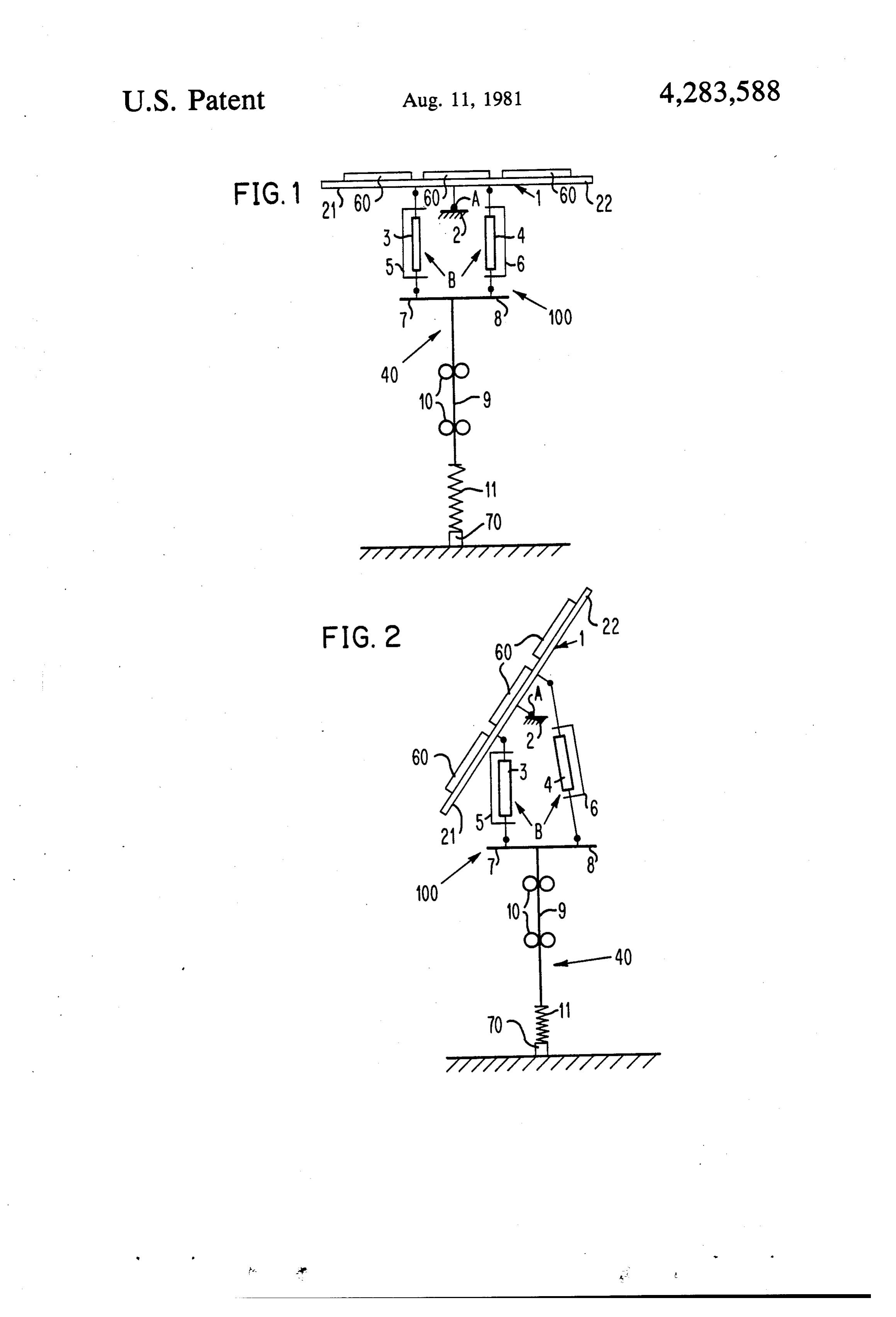
FIG. 1 is a schematic front side view of the present outward movement of the piston rods. When the liquid invention; and cools and contracts, forces acting inward move the FIG. 2 is a schematic front side view of the present 30 piston rods linearly inward.
invention in an extreme position. The heat expansion body B will be effected by all DESCRIPTION OF THE PREFERRED means of heat transfer, such as conduction and convec EMBODIMENT tion from the ambient air and heat radiation from the 35 sun transmitted into or absorbed by the body B. As
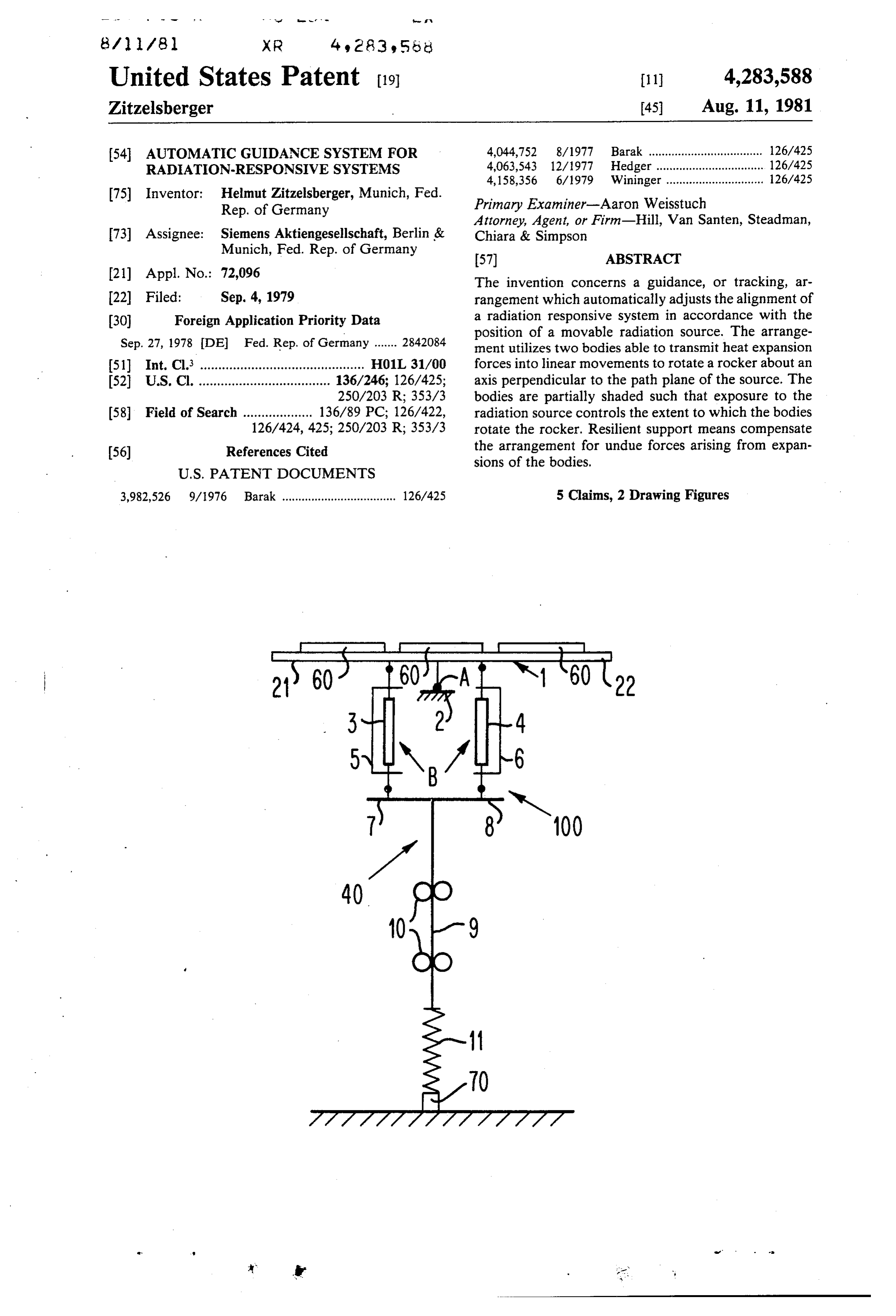
The preferred embodiment is directed to an auto shown in FIG. 1, two expansion bodies 3 and 4 are matic guidance arrangement for a solar cell system. It positioned so as to be spaced-apart and in parallel and will be understood, however, that the principles of the situated on either side of the vertical plane containing present invention would be applicable to other types of the rotation axis A. The bodies 3 and 4 extend between radiation-responsive systems. For example, the arrange 40 the lower surface of the rocker 1 and a platform support ment according to the invention could be utilized with means 40. Body 3 is connected in a known manner, so as any sun-oriented system, such as a solar heater or sun to be rotationally movable, such as pivot joint, at the shield. outer ends of its linearly moving members along arm 21 . For the purposes of the preferred embodiment, the of the rocker 1 and leg 7 of the platform means 40, rocker functions as the system carrier. This form of 45 which are closest to the point of emergence of the sun. arrangement obviates the need for extraneous means to Body 4 is connected so as to be rotationally movable in transmit rocker movements to the system carrier. a similarly known manner at the outer ends of its lin FIG.1 schematically illustrates a guidance arrange early moving members along arm 22 of the rocker 1 and ment 100 of the present invention, wherein a planar leg 8 of the platform 40, which are furthest from the rocker 1 is pivotally supported about a fulcrum 2. An 50 point of emergence of the sun but closest to the sun's array of solar cells 60, such as photovoltaic cells, is point of departure.
positioned, or carried, along the upper surface of the The two expansion bodies 3 and 4 are surrounded by rocker 1. The cells 60 serve as a solar radiation-respon hollow shades 5 and 6, respectively, which partially sive system. The radiation source, the sun, is movable in cover each of the bodies 3 and 4 such that only one side a predetermined path beginning (sunrise) to the left of 55 remains open. The shading means 5 and 6 serve to pre FIG. 1 and traveling in an arc over the system 100 until vent heat radiation from the sun from engaging the departing (sunset) to right of FIG. 1. expansion bodies 3 and 4 and, so, control the extent to The rocker 1 pivots on the fulcrum 2 about an axis of which the bodies 3 and 4 rotate the rocker 1. The shades rotation A. Known support means, such as a pivot joint, 5 and 6 are made with heat insulation material, such as may be utilized to mount the rocker 1 in the fulcrum 2. 60 wood, and may be mounted in a known manner against The rotation axis A is positioned to run perpendicularly the bodies 3 and 4.
to the path plane formed by the travel arc of the sun, so The shades 5 and 6 are formed so that the exposed that the rocker 1 may be adjustably tilted about the axis sides of the expansion bodies 3 and 4 substantially face A to face the sun. In this manner, the solar system 100 one another. The shades 5 and 6 may, however, be can be maintained in alignment with the sun such that 65 slightly twisted with respect to each other such that the very low angles of incidence are effected and perfor open sides lie at an angle of approximately 15 to one mance of the system 10 is optimized throughout the another. This offset prevents the bodies from shading day. one another and, thereby, interfering with the con
Page 5
trolled influence the sun's radiation is to exert on the level as shown in FIG. 1 until re-emergence of the sun bodies 3 and 4. and repeat of the tracking process. The platform means 40 is mounted so as to be resil Since the expansion bodies B are influenced by heat transfers other than sun radiation, resilient platform iently movable in a vertical line perpendicular to the means 40 also serves to accommodate movements of the axis A. Legs 7 and 8 extend perpendicularly from the 5 bodies B due to the other heat transfers, such as air upper end of a vertically extending brace 9. For the temperature purposes of the preferred embodiment, the brace 9 is of the rockerconduction, without affecting the position supported for linearly resilient movement by means of correspondingly maintains themovement 1. The pivoting solar of the rocker 1 system 60 in posi upper and lower bearing guides 10 and a spring means 10 tions of low angles of incidence with the sun throughout 11 connecting the lower end of the brace 9 to a fixed the day. The inventive guidance arrangement accom ground support 70.
Operation of the guidance arrangement of the pre plishes its function without the need for complicated apparatus or the expenditure of externally produced ferred embodiment is as follows. During the sun's emer energy.
gence from the left of FIG. 1, the heat radiation from 15 Although various minor modifications may be sug the sun will cause thermal expansion in the expansion gested by those versed in the art, it should be noted that body 4 since the only side exposed by the shade 6 faces such modifications are to be embodied within the scope the emergence position of the sun. The heat radiation of the patent warranted hereon.
will not influence thermal expansion in body 3 because I claim as my invention:
shade 5 blocks radiation incidence from the emerging 20 1. Apparatus for the automatic alignment of a radia sun positions. Thermal expansion in body 4 is transmit tion responsive system according to the position of a ted in the form of linear outward movements serving to movable radiation source comprising: propel the rocker 1 about its axis of rotation A, such (l) a rocker means carrying said radiation responsive that system 60 is brought into lower angles of incidence system, said rocker means being rotatable about an with the sun. A tensile force. due to movement of the 25 axis which intersects with the plane of movement rocker 1 against the non-expanding body 3 counteracts of said movable radiation source, with the expanding movement of the body 4 until finally (2) a platform means mounted for reciprocable trans the rocker 1 cannot be pivoted further as illustrated by lation in a direction perpendicular to said axis, FIG. 2. Should further outward movement by body 4 (3) two heat expansion bodies positioned between be possible when the rocker 1 reaches its extreme posi 30 said rocker and platform means for exposure to said tion on the fulcrum 2, the resilient platform means 40 radiation source, said bodies being mounted in can be moved vertically downward against the face of spaced-apart fashion on opposed sides of said axis, spring 11. each body having first and second end portions As the sun continues along its arc-shaped path, the linearly, longitudinally movable in response to exposed side of expansion body 4 is irradiated at increas 35 thermal expansion forces occurring within the heat ingly oblique angles such that radiation heating is not as expansion body, intense. The sun's rays begin to engage the expansion (4) means pivotally connecting respective first ends body 3, so that thermal expansion occurs therein. Linear of said heat expansion bodies to said rocker means outward movements transmitted from the body 3 serve 40 and respective second ends of said heat expansion to rotate the rocker 1 against the dissipating expansion bodies to said platform such that linear movements of said first and second ends serve to rotate said forces of body 4. - rocker means about said axis and translate said When the sun stands directly over the guidance ar platform means, and rangement 100, both bodies 3 and 4 are equally exposed (5) shade means for shading each body from exposure to the sun's radiation energy. The forces of expansion in 45 to said radiation source such that relative thermal the bodies 3 and 4 being equal, the rocker 1 lies level as expansion forces are formed in said bodies. shown in FIG. 1. Further thermal expansion in the 2. The apparatus according to claim 1, further com bodies 3 and 4 is accommodated by linear movement of prising:
the platform means 40 against the spring force 11. means for resiliently suspending said platform means. As the sun departs, body 4 is more and more shaded 50 3. The apparatus according to claim 1, wherein said from the sun's rays by means 6. On the other hand, body shade means partially enclose each said body such that 3 is increasingly exposed to the sun's energy. The in uncovered sides of said bodies generally face one an creasingly greater thermal expansion in body 3 tips the other.
rocker 1 about the axis A into positions where the sys 4. The apparatus according to claim 3, wherein said tem 60 faces the departing sun. When the sun departs 55 shade means are formed such that said uncovered sides and the rocker 1 is in the other extreme position directly do not directly face one another. opposite from that shown by FIG. 2. 5. The apparatus according to claim 1, wherein said With the disappearance of the heat source, thermal radiation responsive system comprises an array of solar expansion in body 3 dissipates until the expansion forces cells. sk k k e in the bodies 3 and 4 are equal. The rocker 1 is then held 60
Provenance
- Collection
- Cited prior art
- Original PDF
- patentimages.storage.googleapis.com →
- Filed
- 1979-09-04
- Pages
- 5
- Method
- pdftotext (the PDF's own text layer) + pdftoppm 300dpi page scans
- Source
- Google Patents bibliographic record
- Granted
- 1981-08-11
- Inventors
- Helmut Zitzelsberger; Siemens AG
- Transcribed from
- patentimages.storage.googleapis.com →