patent · US2745042
Automatic ignition mechanism for gas burners
8 May 1956
Page 1 — bibliographic record
May 8, 1956 J. M. HOFF 2,745,042
AUTOMATIC IGNITION MECHANISM FOR GAS BURNERS
Filed July 4, 1952
24-4A-44-444-444-4444444444444-4A-444-444-4Aa-44/aaaaaaaaaaaaaaaaaaa-4444444444444444
Z4444 ZZZZZZP
a %36% 7. 2 INVENTOR.
NZ 3N 2 Š /3 -
/9 ŠEŠEŠ N "(4a A J2a272, '. t 80 at: Z2 Azaz,
Page 2
United States Patent Office Patented May 8, 1956
reason during the operation of the burner the movable arm will cool and close the thermally responsive Switch 2,745,042 which will effect the re-energization of the electric igni tion element which will then re-ignite the side jet.
AUTOMATIC IGNITION MECHANISM FOR GAS 5 The principal object of the invention is to provide a BURNERS very efficient, simple and inexpensive automatic ignition John M. Hoff, Mansfield, Ohio, assignor (2 The Tapail mechanism for the top burner of cooking ranges. Stove Company, Mansfield, Ohio, a corporation of Ohio Other and more limited objects of the invention will be apparent from the following specification and the
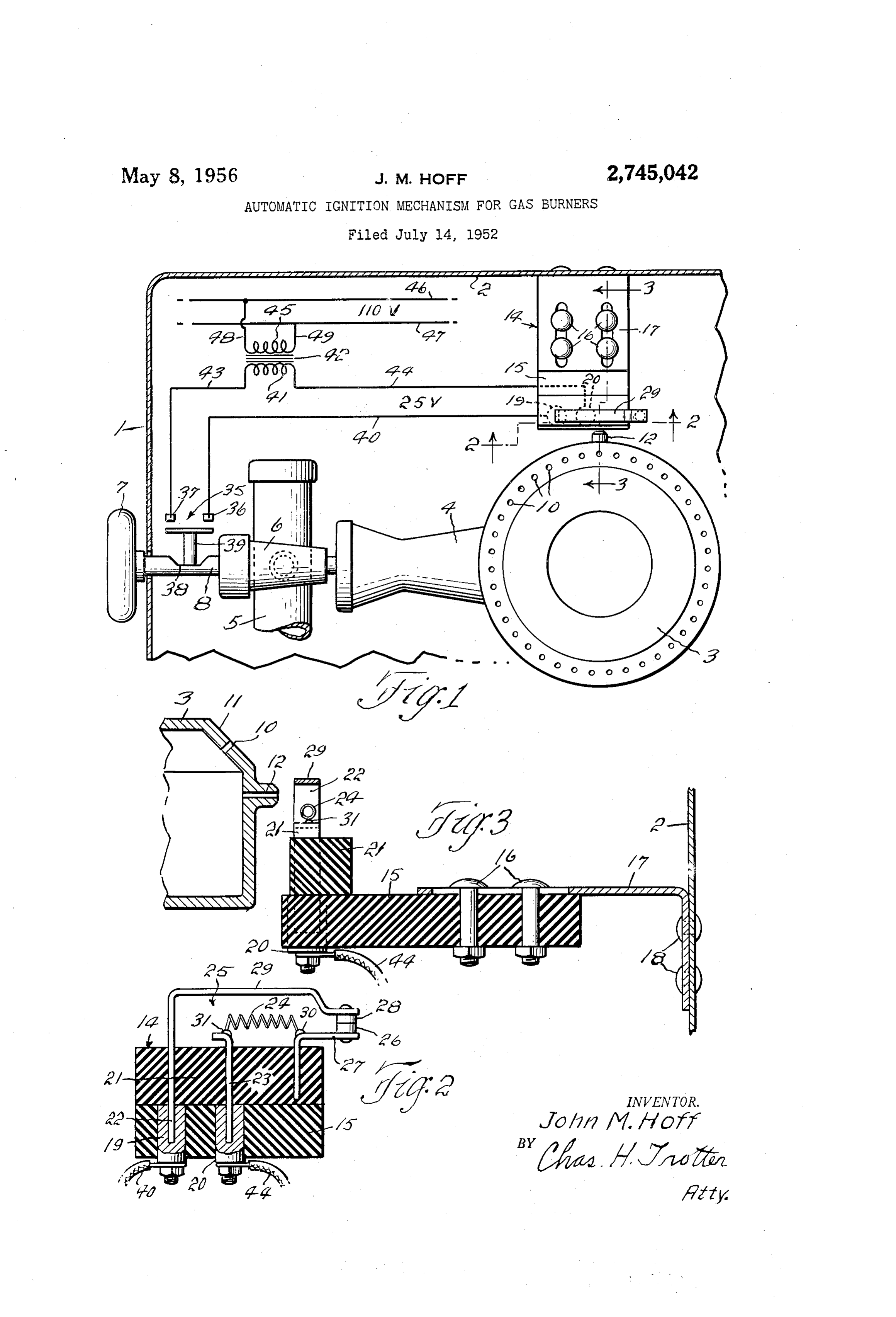
Application July 14, 1953, Serial No. 367,833 O accompanying drawings forming a part thereof in which: 3 Claims. (C. 31.7-83) Fig. 1 is a diagrammatic layout showing my invention applied to a top burner of a cooking range;
Fig. 2 is an enlarged vertical sectional view taken on the line 2-2 of Fig. 1; and
This invention relates to an automatic ignition mech Fig. 3 is an enlarged vertical sectional view taken on anism for the top burner of cooking ranges using gaseous the line 3-3 of Fig. 1.
fuel. Referring now to the drawings by reference characters Heretofore automatic ignition mechanisms of this gen the numerals 1 and 2 are applied to the front and one side eral type usually included a gaseous fuel pilot burner wall respectively of a cooking range, and the numeral 3 which was remote from the main burner and was Sup 20 to one of the top burners therefor. Gas is supplied to the plied with fuel through a separate conduit which was burner 3 through its mixing tube 4 from a fuel supply independent of the main burner. The valve which con manifold 5. A cut-off valve 6 which is adapted to be trolled the supply of fuel to the main burner also con manually opened and closed by a handle 7 and valve trolled the supply of fuel to the pilot burner and was 25 stem 8 is provided to control the supply of fuel to the therefore necessarily more complicated and expensive burner 3.
than a valve which controlled only the Supply of fuel to The burner 3, as shown herein, is generally ring-shaped the main burner. When turned on the pilot burner Was and has a plurality of main jets or orifices 16 arranged ignited by an electric resistance element and the pilot in an annular row in the bevelled surface 11 adjacent burner in turn ignited the main burner through a flash 30 the top of the burner, and an auxiliary jet or orifice 2 tube which extended between the pilot burner and the which extends radially outwardly from the side of the main burner. burner below the annular row of main jets 10. When My new and improved ignition mechanism enables me fuel is supplied to the burner 3, by the opening of the to eliminate the pilot burner, the supply conduit therefor, valve 6, the auxiliary jet 12 is automatically ignited by the flash tube, and the complicated control valve, thus an electric ignition mechanism generally indicated by the providing a much simpler and a much less expensive, but numeral 14, and the main jets is are ignited by the aux nevertheless a very efficient automatic ignition mechanism. iliary jet 12.
In accordance with my invention I provide the main The electric ignition mechanism 14 comprises an arm burner with a single jet which extends outwardly from 15 of suitable insulating material which is adjustably the side of the burner below the main jets, and I mount secured by bolts i6 to a bracket 17 which is secured to an electric resistance ignition element in close proximity the side wall 2 as indicated at 18 and extends inwardly to the discharge end of the jet. When turned on the therefrom. The free end of the arm 15 has a pair of electric ignition element ignites the side jet and it in turn vertically disposed electric connector sockets i9 and 20 ignites the main jets of the burner. The electric ignition suitably secured therein. A block 21 of suitable insulat element is carried by a block of insulating material in ing material has a pair of vertically disposed connector series with a normally closed thermally responsive Switch 45 prongs 22 and 23 mounted therein, which extend down which is also mounted upon the block of insulating ma below the block 21 and are adapted to be removably terial. The thermally responsive switch comprises two seated in the sockets 19 and 20 respectively. The block normally engaging contacts, one of which is carried by 21 also carries an electric resistance ignition element 24 a fixed stationary arm and the other of which is carried and a normally closed thermally responsive switch gen by a movable arm which is adapted to flex and move the erally indicated by the numeral 25.
contact carried thereby out of contact with the other The switch 25 comprises a stationary contact 26, contact when heat is applied thereto. The movable arm which is secured to a conductor arm. 27 carried by the is disposed above the electric ignition element in posi block 2, and a movable contact 28 which is secured to tion to be heated by the small flame from the side jet the free end of a horizontally disposed bimetallic con after it has been ignited by the electric ignition element. 55 ductor arm. 29, the other end of which is connected to The thermally responsive switch is disposed in series with the upper end of the prong 22. The electric resistance a normally open switch which is adapted to be closed by ignition element 24 which consists of a short helical coil the opening of the burner control valve and to be opened of fine wire has one end connected to the conductor 27, by the closing of the burner control valve. in operation as indicated at 30, and the other end thereof connected the burner control valve is manually opened, to Supply 60 to the projecting upper end of the prong 23 as indicated fuel to the burner, which simultaneously closes the nor at 3.
mally open switch and effects the energization of the A normally open switch 35 having the terminals 36 electric ignition element which then ignites the side jet and 37 is mounted adjacent the valve 6 and is adapted which in turn ignites the main jets of the burner. After 65 to be opened and closed by a can 38 carried by the the movable arm of the normally closed switch has been valve stem 8 through the medium of a plunger 29. The sufficiently heated by the flame from the side jet it will arrangement is such that the switch 35 is simultaneously flex and open the normally closed switch and thereby closed with the opening of the valve 6 and is simul break the circuit to and de-energize the electric ignition taneously opened with the closing of the valve 6. The element. The burner will remain ignited until the fuel 70 terminal 26 is connected to the socket 19 by a lead 40 supply therefor is cut off by the closing of the control and the terminal 37 is connected to one side of the sec valve. If the side jet should be extinguished for any ondary winding 41 of a transformer 42 by a lead 43.
Page 3
The other side of the secondary winding 41 is connected thereof being adapted to be received in a socket, a ther to the socket 20 by a lead 44. The primary winding 45 mally responsive arm secured to the upper end of said of the transformer is connected to the house line 46-47 first prong and extending outwardly therefrom substan by the leads 48 and 49. tially parallel to said base, a stationary contact carried In operation the valve 6 is manually opened by the 5 by said conductor arm, a movable contact carried by said turning of the handle 7 and valve stem 8, to Supply gas therinally responsive flexible arm in engagement with to the burner 3. The opening of the valve 6 simul Said stationary contact, and electric ignition means con taneously closes the normally open switch 35. Current nected between said conductor arm and said second prong, then fows from one side of the secondary winding 42 said means thereby being in circuit with and controlled through the lead 43, switch 35 and iead 48 to the socket O by Such contacts, said thermally responsive flexible arm 19. From the socket 19 the current flows through the being operative when heated to move said movable con prong 22, arm. 29, contacts 28 and 26, conductor arm 27 tact out of engagement with said stationary contact. and electric resistance element 24 to the prong 23, and 2. A combined electric ignition means and a thermally from the prong 23 the current flows back to the other responsive control switch therefor as defined in claim 1 side of the secondary winding through the socket 28 and in which said electric ignition means comprises a helical lead. 4. This energizes the ignition element 24 which coil of fine electric resistance wire having one end thereof then ignites the auxiliary jet 12 which in turn ignites the connected to said conductor arm and the other end there main jets 6 of the burner 3. After being ignited the of connected to said second prong. jet 2 projects a flame against the bimetallic arm. 29. 3. A combined electric ignition means and a thermally responsive control switch therefor which is adapted to be
After the arm 29 has been sufficiently heated it will flex and separate the contacts 26 and 28 which will break the removably mounted in a cooking range in position to circuit to and deemergize the ignition element 24. To ignite a gaseous fuel burner and comprises, a base of terminate operation the valve 6 is closed and the Switch insulating material, a first prong and a second prong car 35 simultaneously opened by the handle 7 and valve ried by said base with the upper ends thereof disposed stem 8. After the jet 12 is extinguished by cutting off. above said base and the lower ends thereof disposed be the Supply of gas thereto the arm 29 will cool and close low said base and adapted to be received in a socket, a the Switch 25. The mechanism is then in condition for conductor arm carried by said base, said prongs and the next operation thereof. Said conductor arm being disposed in longitudinal align if the ignition element 24 burns out or the switch 25 ment with each other with said second prong disposed becomes inoperative for any reason, the block 21 may 30 between Said first prong and said conductor arm, a be removed and discarded and another block 21 having thermally responsive flexible arm secured to the upper an unimpaired ignition element and switch substituted end of said first prong and extending outwardly there therefor. from Substantially parallel to said base above said second From the foregoing it will be apparent to those skilled 3 5 prong and said conductor arm and in vertical alignment in this art that I have provided a very simple, efficient therewith, a stationary contact carried by said conductor and inexpensive mechanism for automatically igniting a arm, a movable contact carried by said thermally re cooking range burner whenever the control valve there Sponsive flexible arm in engagement with said stationary for is opened to supply gas thereto. contact, and an electric ignition element disposed under It is to be understood that I am not limited to the Said thermally responsive flexible arm and comprising a Specific construction shown and described herein as var 40 helical coil of fine electric resistance wire having one ious modifications may be made therein within the scope end thereof connected to said second prong and the other of the appended claims. end thereof connected to said conductor arm, said ther What is claimed is: nally responsive flexible arm being operative when heated 1. A combined electric ignition means and a ther to move said movable contact out of engagement with mally responsive control switch therefor which is adapted 45 said stationary contact.
to be removably mounted in a cooking range in position to ignite a gaseous fuel burner and comprises, a base of References Cited in the file of this patent insulating material, a first connector prong carried by UNITED STATES PATENTS Said base, a conductor arm carried by said base, a second 50 2,596,505 Pacifico --------------- May 13, 1952 connector prong carried by said base, said prongs ex 2,635,003 Perl ------------------ Apr. 14, 1953 tending above and below said base with the lower ends
Provenance
- Collection
- Cited prior art
- Original PDF
- patentimages.storage.googleapis.com →
- Filed
- 1953-07-14
- Pages
- 3
- Method
- pdftotext (the PDF's own text layer) + pdftoppm 300dpi page scans
- Source
- Google Patents bibliographic record
- Granted
- 1956-05-08
- Inventors
- John M Hoff; TAPPAN STOVE CO
- Transcribed from
- patentimages.storage.googleapis.com →