patent · US2800176
Automatic gas ignition and burner control system
23 July 1957
Page 1
Drawing sheet — no readable text.
Page 2
Drawing sheet — no readable text.
Page 3
United States Patent Office 2,800,176 Patented July 23, 1957
February 9, 1953, and entitled “Electrically Controlled
Safety Igniter Circuit for Gas Burners.'
2,800,176 These and other objects of my invention will appear
AUTOMATIC GAS GNITION AND BURNER
from to time as the following specification proceeds and
CONTROL SYSTEM
with reference to the accompanying drawings wherein:
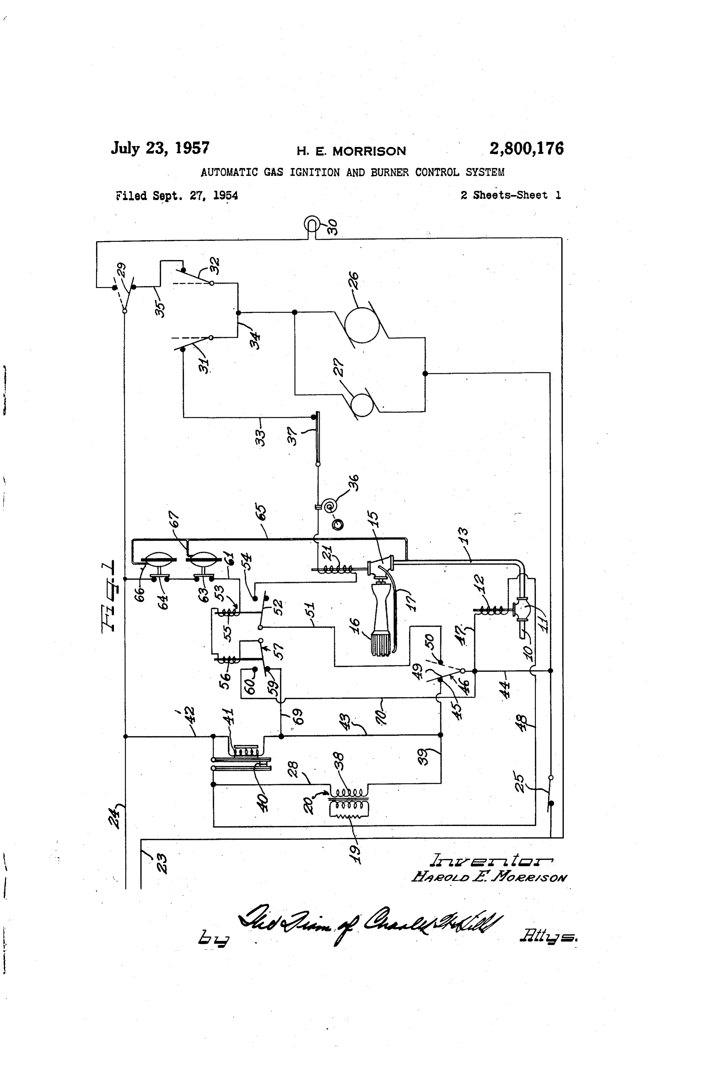
Figure 1 diagrammatically shows an automatic gas
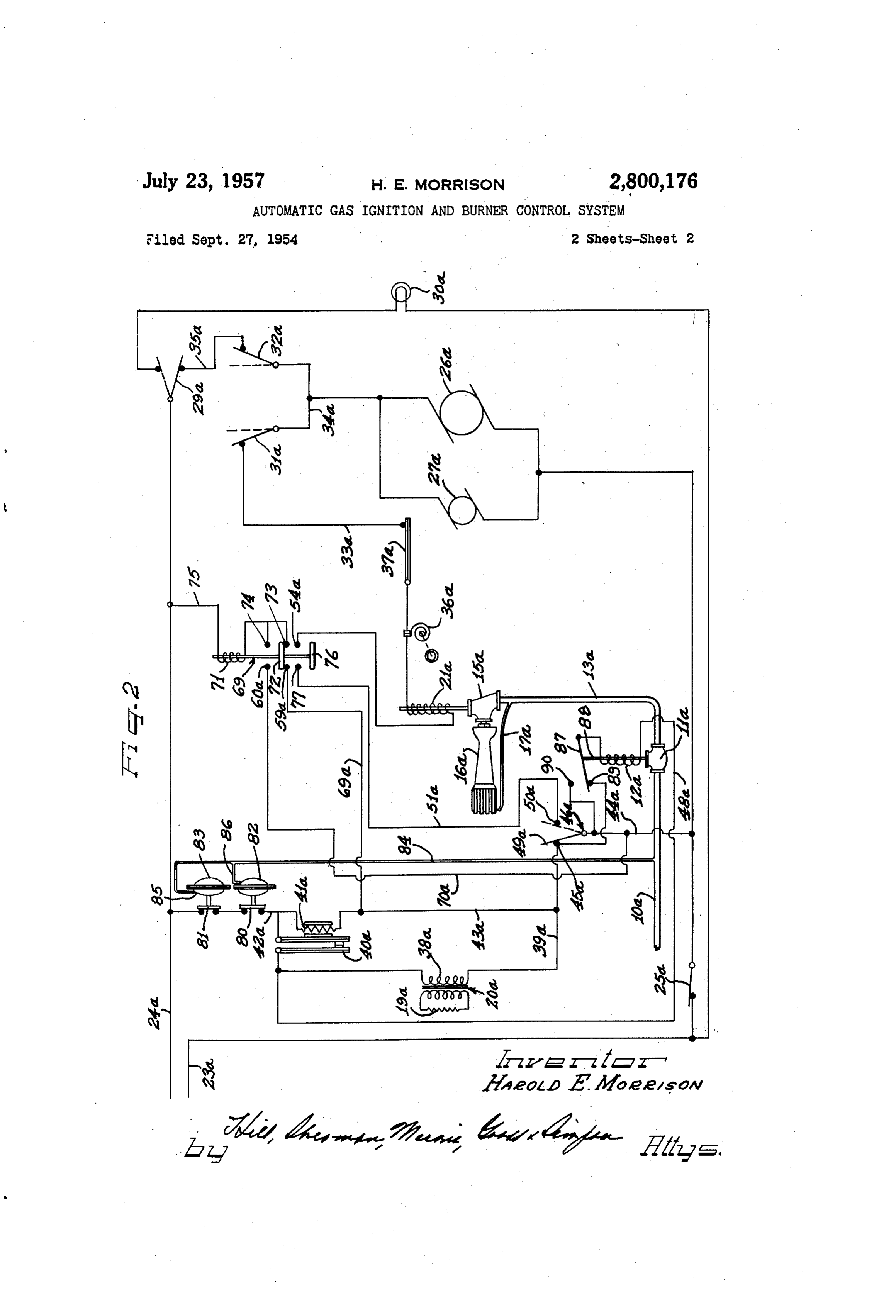
Harold E. Morrison, Beaton Harbor, Mich., assignor, by ignition and burner control system constructed in accord mesne assignments, to Whirlpool-Seeger Corporation, ance with my invention and connected in the burner and St. Joseph, Mich., a corporation of Delaware electric circuit of an automatic clothes dryer; and Application September 27, 1954, Serial No. 458,455 O Figure 2 illustrates a modified form of gas ignition and burner control system having my invention embodied
The automatic pilot of my invention is herein shown as being operative to ignite and control operation of the
This invention relates to automatic pilots and more 15 burner of a clothes drier, and as being connected in the particularly to electrically operated automatic pilots for electric control circuit for rotatably driving the drier al gas burners, to turn the gas supply on and off upon failure though it need not be connected in such a circuit and may in the gas and electric system, and to ignite the main be utilized in any desired gas burner circuit. The control burner. circuit for the drier is somewhat similar to that shown Heretofore, electrically ignited pilots and automatic 20 and disclosed in my joint application with Peter E. controls for the gas supply system for igniting the main Geldhof et al., Serial No. 208,708, filed on January 31, burner and turning of the gas supply upon failure of the 1951, and now Patent No. 2,678,814 dated May 18, 1954, gas Supply or electric controls have been used in various so the drier and the circuit thereto need only be de types of gas heated apparatus. Such pilots, however, Scribed herein to the extent sufficient to make my present have been slow to operate, both in turning on and turning invention readily understandable. off the gas supply and in igniting the main burner, with A pipe 10, connected to a gas supply line is shown as the result that there is frequently an accumulation of gas, delivering gas to a pilot or main gas supply valve 11 op due to the time lag in shutting off the gas after the failure, erated by a Solenoid 12. A pipe 13 connects the main or to the time lag in igniting the burner after the gas gas Supply valve 11 with a control valve 15 for a main Supply is turned on, with the result that minor explosions 30 burner 16. A pilot burner 17 leads from the supply side frequently occur. Due to this difficulty in providing a of the valve 5 to a position adjacent the burner 16 positive and fast acting automatic pilot the standards for igniting said burner and is supplied with gas as long which have been set up by the American Gas Association as the valve 1 is open. The pilot flame is ignited by a of Cleveland, Ohio, allow a time variation of up to five glow coil 9 energized by the secondary of a transformer minutes to turn off the main burner after a current inter 20. The glow coil 19 is positioned adjacent the pilot 17, ruption. While this time lag is exceedingly long, it is not but for convenience in illustrating the control circuit, said exceedingly dangerous for certain types of apparatus, glow coil is herein shown as being remote from the pilot. such as ovens and heating furnaces, even though un A solenoid 24 is provided to operate the main burner desirable and a potential source of danger and has of valve 5.
necessity been set up as a standard because no pilot has 40 The valves 11 and 15 may be of any well known form heretofore been found which would immediately shut-off of solenoid-operated gas control valve, one form of con the gas supply as soon as the pilot flame goes out or a struction of said valves being illustrated in my joint current interruption occurs. patent with Peter E. Geldhof et al., No. 2,678,814 referred My invention has as its principal objects to provide an to before. Said valves are no part of my present inven automatic pilot which will instantaneously close the gas tion so need not herein be shown or described further. Supply and prevent unburned gas from passing through Electric power to drive the drier motors and energize the main burner, upon interruption of the electric system the system is provided through conductors 23 and 24, or upon failure or excessive pressure in the gas supply connected with a suitable source of electric power. A line. switch 25 is shown as being connected in the conductor Another object of my invention is to provide an auto 50 23, to deemergize the entire drier circuit. A motor 26 is matic pilot and an electric igniter for the pilot flame shown as being provided to drive the drier drum and a wherein the gas supply will be immediately shut-off upon timing motor 27 is provided to drive the timer for timing interruption of the electric system, and wherein the power the operations of the drier, and to control the energization may be turned back on again as soon as the pilot flame is of the solenoid 21, to turn the supply of gas for the drier out. 55 burner 6 "on' and “off” at predetermined time inter A further object of my invention is to provide an vals, as is well known to those skilled in the art and no automatic pilot and electric igniter for the pilot gas part of my present invention so not herein shown or de which will automatically shut-off the gas Supply if the gas scribed further. A switch 29 is shown as being provided pressure is too high or too low. in the conductor 24. This switch may be a door operated A still further object of my invention is to provide a 60 Switch and is shown as connecting a lamp 30 in the circuit simplified and novel form of control for an automatic upon opening of the door, to light the inside of the drier, pilot so arranged as to render it impossible to supply gas and as disconnecting the motors 26 and 27, and solenoid to the main burner when the pilot is out. 2 from the circuit when the door is opened. A still further object of the invention is to provide an It should here be noted that upon door opening automatic gas ignition and burner control system in which 65 movement the gas supply to the burner i5 is turned off, the ignition system and master and main burner valves but the gas supply valve 11 remains open and pilot are shut-off except when the gas pressure is such as to burner 7 remains on to again ignite the burner when the door is closed, provided the switch 25 remains closed.
assure safe ignition of the pilot and main burners.
This application is a continuation-in-part of my appli Switches 31 and 32 operated by the timer motor 27 are cations, Serial No. 168,638, filed June 16, 1950, now 70 likewise shown as being connected in the control system. abandoned, and entitled "Automatic Gas Ignition and series The switches 31 and 32 are shown as being connected in Burner Control System,' and Serial No. 335,646, filed in the return from the solenoid 21 to the switch
Page 4
29, through conductors 33, 34 and 35. The conductor of said switch, which will hereinafter be termed the hot 33 has an adjustable thermost at 36 therein, which may contact of said switch.
be manually set to control the drier temperature. It also In normal operation after the flame detecting switch has a safety thermostat 37 therein. The safety thermo 50 has moved to its hot position, to effect energization stat 37 is shown as being in the form of a bimetal switch 5 of the solenoid 21 of the main burner valve 15, the main and opens the circuit to the coil 21, if for any reason the gas supply valve solenoid 12 remains energized through temperature within the drier should become too high the contacts of the warp switch 40. The primary 30 of and the thermostat 36 should not function.
The return from the motors 26 and 27 is connected in O the transformer 20 and the heater coil 41 are deenergized because of the shifting of the contact arm 49 to its hot the conductor 34 between the switches 31 and 32. The position, - switches 31 and 32 are closed upon the setting of the The hot contact 50 is connected with a conductor 51 timer motor 27 to a timed position and will remain closed shown as being connected with a contact arm 52 of a for predetermined periods of time. The switch 32 may relay 53. Said contact arm is engageable with a contact open at a delayed time interval after opening of the switch 54 of said relay when said relay is energized, to close 31 to circulate the clothes after the main burner is turned off. the circuit to the solenoid 21 and open the main gas burner under control of said relay and said hot contact
A primary coil 38 of the transformer 20, energizing 50 of the switch 46.
the glow coil 19 through the secondary of said trans An operating coil 55 of the relay 53 is herein shown former, is connected in the circuit through a contact 45 20 as being connected in series with a coil 56 of a relay 57. and switch arm 49 of a flame detecting pilot switch 46, The relay 57 is adapted to close a circuit from the cold when said flame detecting switch is in its cold position. contact 45 of the pilot switch 46 through a contact 59 and The contact 45 is hereinafter referred to as the cold con energize the coils 56 and 55 and close said relays. When tact of said switch. The connection from said contact 45 the relay 57 has been closed by the energization of its to energize the primary 38 of the transformer 20 includes coil through the contact 59, the circuit through said con a conductor 39 connected with the contact 45, the con tact is broken, and the coils 56 and 55 are held ener tacts of a bi-metal warp switch 40 and a conductor 42 gized through a contact 60 of the relay 57. Current is connected with the line 24. A heater coil 41 of the bi conducted to the contact 60 by a conductor 70 directly metal warp switch 40 is likewise connected with contact connected with the conductor 44. While I herein show 45 through the conductor 39 and a conductor 43. 30 two relays one of which serves to energize and hold the The heater coil 41 is provided to heat the bi-metal relays closed and the other of which serves to complete warp switch 40 and open the contacts thereof in a pre a circuit through the solenoid coil 21 to close the main determined time delay interval and deemergize the burner valve 15, it should be understood that I need ignition circuit, should the pilot burner fail to ignite in not have two relays, and that one relay with multiple a period of time of from approximately three to five Sets of contacts will serve as well, and that two relays minutes at normal line voltage. The contacts of said are only shown as a matter of convenience in illustrating warp switch 40 are normally closed, and open to de the circuit. - -- - . .. .. . . .. . . . . . . --
energize the solenoid 12 of the pilot or main gas supply A conductor 61 having two pressure operated switches valve 11, and shut-off the supply of gas in case the flame. 63 and 64 therein, herein shown as being diaphragm detecting switch 46 should not pass from its cold to the 40 Switches of a suitable construction serves to connect the hot position, as when the pilot should fail to ignite. coils 55 and 56 to the return 24. The diaphragm cham Upon opening of the warp switch 40 and failure of the ber of the Switch 64 is connected with the gas supply switch 46 to pass from its cold to hot position, the circuit line 13 through a pipe 65 connected to one side of the to the primary coil 38 of the transformer 20 will be indicated diaphragm (not shown) of the diaphragm switch 64 as opened, deenergizing transformer 20 and glow coil 19. at 66. A branch pipe 67 leading from the The heater coil 4i, however, will remain energized pipe 65 is connected to the opposite side of the diaphragm through the contact arm 49 and contact 45 of the flame chamber and diaphragm of the switch 63 from the switch detector switch 46. - - -- - 64. The Switches 63 and 64 are held in a closed posi The solenoid 12 is connected in the circuit through a tion during normal gas pressure in the line 13. The switch 63, however, opens its contacts upon a reduction conductor 44 connected with the conductor 23, a con 50 in ductor 47 connected from the conductor 44 to said sole Safegasvalue pressure in said supply line below a predetermined while the Switch 64 opens its contacts upon noid and a conductor 48 connected from said solenoid pressure in said gas supply line above a predetermined safe through the contacts of the "warp switch 40 and through the contacts of said warp switch to the conductor 42. value. The circuit to the coils for the relays 53 and 57 The contacts of the warp switch 40 are initially closed 55 will thus be broken and said relays will open upon a when starting operation of the drier and remain closed or reduction or increase in pressure in the gas line 13 below during normal operating conditions to energize the sole opening above a predetermined normal or safe value. The noid 12 of the main gas supply valve 11. of said relays will thus deemergize the solenoid The circuit to the heater coil 4 is closed as long as valye 21 and effect closing the burner valve 15. The pilot the Switch 25 is closed and the contact arm 49 of the 60 11, however, will remain open to again ignite the flame detecting switch 46 is in engagement with the cold main burner 16 when the pressures in the line 13 again contact 45. The heater coil 41 will therefore warm the reach the desired safe operating value. If, however, the Switch 41 until the pilot is ignited and the flame detector pressure should be so low that the pilot flame will go out. switch 46 passes from its cold to its hot position. Once the contact arm 49 of the flame detector switch 46 will the Warp Switch 40 opens, said switch will remain open 65 move to the cold position. The main burner valve 15 then cannot be opened until the pilot has been ignited until the heater coil has cooled upon the breaking of the and the circuit through the hot contact 50 of said switch circuit thereto as by opening of the switch 25. 46 is closed. . .. . . . . . The flame detecting pilot switch 46 may be of a type Upon failure of power, the relays 57 and 53 will im similar to that shown and disclosed in my joint Patent mediately open, deenergizing the coil of the solenoid 21 No. 2,678,814 with P. E. Geldhof et al., mentioned be 70 and effecting closing of the main burner valve 15. The fore, and is no part of my present invention so need not Solenoid 12 of the pilot valve 11 will also be deemergized, herein be shown or described in detail. Upon the light effecting ing of the pilot 17 by the glow coil 19, the heat of the closing of said valve. The contact arm 49 of the pilot flame will move a contact member 49 of the switch flame detecting switch 46 will then move to engage the into position to close a circuit through the contact 50 75 contact 45 and the circuit will be in the open position shown, assuming the drier door is closed. When power
Page 5
is again turned on, with the switches 25 and 29 closed, contact arm 49 and contact 45 and move the contact the solenoid coil 12 of the pilot valve 11 will be energized arm 49 to close a circuit through the contact 50 of said to open said valve through the conductors 23, 44, 47, 48 flame detecting pilot switch, thus assuring the absence contacts of the warp switch 40 and conductor 42. Cur of raw gas within the drier cabinet. rent will also pass through the contact arm 49 and cold In the modified form of control circuit illustrated in contact 45 of the flame detecting pilot switch 46 through Figure 2, the elements like those in Figure 1 will be re the primary 38 of the transformer 20 and through the ferred to by like reference numerals plus an affix 'a.' heater coil 4;. This will energize the glow coil 19 to In this modified circuit, a relay 69 is shown as taking ignite the pilot 7 and will also heat the bi-metal warp the place of the two relays 53 and 57 and as having a switch 46, preparatory to opening said Switch after a IO solenoid coil 7 energized through the contact 59a, a predetermined time interval if the pilot burner 57 should contact bar 72 of said relay and a contact 73, when the fail to ignite. flame detecting switch 46a is in its cold position, with The coils 55 and 56 of the relays 53 and 57 will also the contact arm 49a in engagement with the contact 45a. be energized through conductor 44, contact arm 49, con The solenoid coil 7 is energized through the conduc tact 45, conductors 39, 43, and 69, contact 59, conductor 5 tor. 70a, contact 60a, the contact bar 72 and a con 62, pressure switches 63 and 64 and conductor 24. This tact 74 when the flame detector switch 46a has passed will break the circuit through the contact 59 and make the to its hot position to engage the contact on 49a with the circuit through the contact 60 of the relay 57, to hold said contact 50a by the heat of the pilot flame. The solenoid relays closed. It will also close a circuit through the coil 7 is shown as being connected to the conductor contact 54 cf the relay 53 and connect the solenoid coil 20 24a through a conductor 75.
2 of the main burner valve 5 to the contact 5 of the The relay 69 also has a second contact bar 76 mov flarine detecting switch 46. able with the contact bar 72 and completing a circuit from As soon as the pilot 7 is ignited, the heat of the pilot the hot contact 50a of the flame detector switch 46a, the flame will move the contact arm 49 of the flame detect conductor 5ia, a contact 77 through the contact bar 76 ing switch 45 into engagement with the contact 50 and 25 to the contact 54a to energize the solenoid coil 21a of complete a circuit through the coil of the solenoid 21 the main burner valve E5a when the pilot burner has been through the conductor 51, contact 54 of relay 53, and to ignited and has generated sufficient heat to effect move the return through the thermostats 36, 37, the conductor ment of the contact arm 49a into engagement with the hot 33 and switches 33, 32 and 29. This will effect opening contact 59a.
of the main burner valve. 30 The circuit to energize the solenoid 2:a is thus the If, however, the glow coil 19 for any reason should same as the circuit in the form of my invention illustrated fail to ignite the pilot burner 7, the arm 49 will stay in in Figure 1 except that a single relay 69 has been substi engagement with the contact 45. The heater coil 41 tuted for the two relays 53 and 57. being energized through the cold contact 45 will effect Two pressure operated switches 80 and 81 are shown opening of the bi-metal warp switch 40 in a delayed time 35 as being provided in the conductor 42a to prevent the interval. This will deenergize the Solenoid 2 and effect energization of the solenoid coil 12a and the opening closing the pilot or main gas Supply valve 15. The pri of the main gas supply valve a except when the gas mary 38 of the transformer 23 and the glow coil 9 will pressure on the Supply side of said main gas supply valve also be deenergized. The circuit to the coil of the sole noid 2 of the main gas supply valve it can, therefore, 40 is aThe predetermined normal pressure. pressure switches 80 and 81 are diagrammatically never be completed until the heater coil 4 has cooled shown as being diaphragm switches like the switches by opening ofthe Switch 25, and the warp switch 40 has closed its contacts. The switch 25 may then be closed 63 and 64 illustrated in Fig. 1 and include diaphragm chambers 82 and 83 respectively connected in the supply and the pilot burner may be ignited. The main burner pipe ita on the supply side of the main gas supply valve valve 15 may then be opened when the pilot has gen Ea through a pipe 84. The diaphragm chamber 83 erated sufficient heat to move the contact arm 49 into is connected with the pipe 84 to one side of the dia engagement with the hot contact 50. phragm (not shown) of the diaphragm switch 81 at 85. Also, the circuit to energize the cois 55 and 56 to A branch pipe 86 leading from the pipe 84 is connected complete the circuit through the contact 50 of the pilot to the opposite side of the diaphragm chamber 82 from Switch 46 to the contact 54 of the solenoid 53 can only the connection of the pipe 84 to the diaphragm chamber be completed when the pressure in the line 13 is a pre 83.
determined normal safe pressure, the switch 63 opening The switches 80 and 81 are closed upon normal gas when the pressure is below a safe normal pressure, and pressure in the pipe 10a. The switch 80, however, opens the Switch 53 opening when the pressure is above a safe its contacts upon a reduction in gas pressure in the gas normal pressure, thus protecting the burner against ex Supply line 16a below a predetermined safe value while cessive pressures, or against pressures so low that the the Switch 81 opens its contacts upon the increase in flames in the burner and pilot are likely to go out. pressure in Said gas supply line above a predetermined Also, if at any time during operation of the drier, the safe value.
pressure should vary below or above predetermined safe normal pressures the relays 53 and 57 will both open. 60 gasThe pressure switches 80 and 8 thus assure that the pressure is up to normal before the main gas supply
The burner waive i5 will then close, the pilot valve a re maining open until a power interruption. When this oc valve can be opened and the glow coil 19a can be ener curs, the relay 53 and 55 can only be closed to again open gized to ignite the pilot burner i7a. This prevents the the burner valve 5, by opening the Switch 25, to break collection of unburned gas in cases where the pressure the circuit through the coil of the solenoid 2, and allow 65 may be so low that the pilot will not ignite until there ing the pilot flame to go out, and accommodating the has been an undue accumulation of gas in the drier cabi pilot switch 35 to cool and open the circuit through the net, and also prevents failure of the pilot to ignite by contact airin 49 and contact 5, and close the circuit eXcessive gas pressures high enough to keep the pilot from through the contact arm 49 and contact 45. igniting until there has been a dangerous accumulation The relays 53 and 57 can, therefore, only be reclosed, O of-gas in the drier cabinet. The pilot burner 17a is thus if for any reason the circuit through their coils has been only Supplied with gas when the gas pressure is such that interrupted, through the cold contact 45 of the flame the glow coil 19a will readily ignite the pilot. detecting Switch 46. Also the main burner valve 5 can It has been found in practice that one of hazards in only be closed after the pilot has been ignited and has operating a gas burner system, particularly by unskilled generated sufficient heat to open the circuit through the 5 persons, lies in the inadvertent pulling out of the elec
Page 6
tric supply cord or opening one of the main electrical to said relay coil through one of said contacts and the control switches and then immediately reestablishing the cold contacts of said flame detecting switch, a second-en ergizing circuit to said relay coil through another of said
It is highly desirable to provide safety means in a gas contacts, said second energizing circuit closing when said burner control system which will, under such circum relay coil is energized, an energizing circuit for said sole stances, shut off both the master valve 11a as well as the noid for said main burner valve through a third set of main burner valve 15a and prevent their reopening until contacts and including the hot contacts of said flame de the flame detector switch has at least returned to its cold tecting switch, and means operative upon energization of position where the igniter is again energized. said relay coil for closing said third set of contacts. In the form of my invention shown in Figure 1 of the () 2. In an automatic gas igniter and burner control sys drawing, the main burner valve cannot be reopened under tem, a gas supply line, a main burner connected thereto, such circumstances until the flame detector switch is a pilot burner also connected thereto for igniting said recycled through its cold position, but means is not pro main burner, electrically energizable means igniting said vided in this first form of my invention for preventing pilot burner, a valve in said gas supply line on the supply reopening of the master valve. side of said main and pilot burners, a solenoid for oper In the form of my invention illustrated in Figure 2, ating said valve, a burner valve on the supply side of means is also provided for preventing reopening of the said main burner, a solenoid for operating said burner master valve. This is accomplished by initially effecting valve, a flame detecting pilot switch closing a circuit energization of the master valve through the cold con 20 through one contact when cold and through another con tact of the flame detector switch and then providing a tact when heated by the presence of a pilot flame, a relay holding circuit therefor which by-passes the flame detector having a coil and a plurality of contacts operated thereby, switch. one of said contacts being closed when said relay coil Specifically, the upper end of the coil 12a is connected is deemergized and connecting the cold contact of said to the movable switch element 87 which is actuated by flame detecting switch with said relay coil, to energize the armature 88 of the solenoid 12a. This switch also 25 said relay coil and open said one contact, another of includes a stationary contact 89 and a stationary contact said contacts being opened when said relay coil is deen 90. The movable switch arm 87 normally connects con ergized and closing upon energization of said relay coil, tact 89 when the solenoid 12a is deenergized and while to maintain the energizing circuit to said relay coil and the stationary contact 90 is connected to the switch arm 30 hold said contacts closed upon movement of said flame 87 when the solenoid 2a is energized. The contact 89 detecting switch from a cold to a hot position, an energiz is directly connected to the cold position contact 45a ing circuit from the hot contact of said flame detecting of the flame detector switch 46a while the stationary switch through a third set of contacts of said relay, and contact 90 is directly connected to conductor 44a. means operative upon energization of said relay coil for From the above description, it will readily be appre closing said third set of contacts to energize said main ciated that the master valve 11a is opened by initial 3 5 burner solenoid upon movement of said pilot switch to energization of the circuit which includes the pressure a hot position only, said relay coil being initially ener switches 80 and 81, the warp switch 40a, the solenoid gizable only through the cold contacts of said flame de 12a of the valve 11a, and the flame detector switch 46a. tecting switch, and fluid pressure operated switching means Upon a flow of electric energy through the solenoid 12a, connected with said gas supply line and deenergizing said the master valve 11a is opened and the movable switch relay coil upon variation in pressure in said main gas arm 87 moves to its upper position in engagement with supply line above or below a predetermined normal pres contact 90 to establish a holding circuit around the flame sure range.
detecting switch. Even upon a momentary interruption 3. In an automatic gas igniter and burner control sys of the power circuit, the solenoid 12a becomes deener tem, a gas supply line, a main burner connected thereto, gized, the holding circuit opens, and the switch 87 drops a pilot burner also connected thereto for igniting said back to its lower position. The master valve 11a can main burner, a valve in said gas supply line on the supply now only be reopened by reenergization of the solenoid side of said pilot and main burners, a solenoid for operat 12a through the flame detector switch. ing said valve, means for igniting said pilot, a main burner The same result will occur if there is even a momen valve on the supply side of said main burner, a solenoid tary variation in gas pressure in the gas supply main 10a for operating said main burner valve and a safety thermo outside of the predetermined range, for this will cause static switch in series with the coil for said last mentioned either pressure switch 80 or pressure switch 81 to open solenoid, a flame detecting pilot switch having two con and effect deenergization of the solenoid 12a. It will tacts and closing the circuit through one contact when thus be seen that a high degree of safety is provided for cold and through the other contact when heated by the any abnormal operation, irrespective of whether it is a flame of said pilot burner, a relay having a coil, a con power failure or an abnormal fluctuation in gas pressure. tact arm operable by said relay coil, two contacts either It will be understood that various modifications and of which is engageable with said contact arm, one of variations of the present invention may be effected with said contacts being connected with the cold contact of out departing from the spirit and scope of the novel con 60 said flame detecting switch and completing a circuit cepts thereof. - through said contact arm and relay coil when said relay I claim as my invention: coil is deenergized and the other of said contacts being 1. In an automatic gas igniter and burner control sys connected to hold said relay coil closed upon movement tem, a gas supply line, a main burner connected thereto, of said contact arm from said one contact to the other of a pilot burner also connected thereto for igniting said said contacts, a conductor connecting the hot contact of main burner, electrically energizable means for igniting said pilot switch with a third set of contacts, a connection said pilot burner, a valve in said gas supply line on the from said third contacts to the coil of the solenoid for supply side of said pilot and said main burner, a solenoid operating said main burner valve, and means operable for operating said valve, a main burner valve on the Sup upon the energization of said relay coil for closing said ply side of said main burner, a solenoid for operating said third set of contacts and energizing said solenoid operating main burner valve and a safety thermostatic switch in 7 said main burner valve upon movement of said flame de series with the coil for said last mentioned solenoid, a tecting pilot switch from a cold to a hot position. flame detecting pilot switch closing a circuit through one 4. In an automatic fuel ignition and burner control contact when cold and through another contact when system including a pilot burner and a valve controlling heated by the presence of the pilot flame, a relay having the supply of fuel to said pilot burner, a main burner a coil and a plurality of contacts, an energizing circuit 75 and a burner valve in series with said first valve for
Page 7
controlling the supply of fuel to said main burner, electro mal operated time delay relay therein having a stationary magnetic means for operating said first valve, electro contact and a movable switch arm normally engaging magnetic means for operating said burner valve, a pair of said contact, and electrically energizable means for dis electrical supply lines, a thermal switch responsive to engaging said Switch arm from said stationary contact, heat of the pilot burner flame and having a movable con an energizing circuit from said conductors to said main tact connected to one of said supply lines, a cold contact burner shut-off valve having a thermally operated switch normally engaged by said movable contact, and a hot therein responsive to the heat of the pilot burner flame contact engaged by said movable contact when said switch and having a cold and a hot contact, an energizing circuit is heated to a predetermined temperature, an energizing from said cold contact to said electrically energizable circuit from said cold contact to the other of said elec 10 means for operating said movable switch arm of said time trical supply lines, a thermally operated time delay relay delay relay, an energizing circuit from said hot contact to having electrically energizable operating means therefor said solenoid for operating said burner shut-off valve, said in said last-mentioned circuit and having normally en energizing circuit for said main gas supply valve having gaged Stationary and movable contacts completing an two pressure switches connected with the supply side of energizing circuit to said electromagnetic means for oper said main gas supply valve, one of said pressure switches ating said first valve, a relay having a coil, first and sec being operable to open the circuit to said solenoid for ond fixed contacts and a movable contact normally en said main gas supply valve upon increases in pressure over gaged with said first contact and moved into engagement pressure predetermined normal pressures, and the other of said with said second contact by energization of said coil, switches being operable to open the circuit to means connecting said relay coil through said first con 20 said solenoid for said main gas supply valve upon de tact of said relay to said cold contact, means connecting creases in pressure below predetermined normal pres said second contact of said relay to one of said electrical sures, to prevent opening of said main gas supply valve Supply lines; a third set of normally open contacts, means except when the gas pressure on the Supply side of said operative upon energization of said relay coil to close said 25 valve is at a predetermined normal pressure, and shut third set of contacts and connect said electromagnetic ting off the supply of gas whenever the pressure on the means for operating said burner valve to the other of said supply side of said main gas supply valve varies from said electrical Supply lines to energize said electromagnetic predetermined normal pressure.
means to operate said burner valve to supply fuel to said 7. In an automatic gas burner ignition and control main burner. system, a gas supply line, a main gas burner connected to 5. In an automatic gas burner ignition and control sys 30 said gas supply line, a burner shut-off valve on the supply em, a gas supply line, a main gas burner connected to side of said main gas burner, a solenoid for operating said gas supply line, a burner shut-off valve on the sup said valve, a pilot burner connected to said gas supply ply side of said main gas burner, a solenoid for operating line on the supply side of said burner shut-off valve, a said valve, a pilot burner connected to said gas supply main gas supply valve on the supply side of said pilot line on the supply side of said burner shut-off valve, a burner, a solenoid for opening said valve, a source of main gas supply valve on the supply side of said pilot electric power comprising a plurality of conductors, an burner, a solenoid for opening said valve, a source of elec energizing circuit from said conductors to said solenoid tric power comprising a plurality of conductors, an ener for operating said main gas supply valve including a ther gizing circuit from said conductors to said solenoid for 40 mal operated time delay relay therein having a stationary operating said main gas supply valve including a thermai contact, a movable switch arm normally engaging said operated time delay relay therein having a stationary con contact and electrically energizable means for effecting tact and a movable switch arm normally engaging said disengagement of said switch arm from said contact, an contact and electrically energizable means for disengag energizing circuit from said conductors to said main burn ing said switch arm from said contact, an energizing cir 45 er shut-off valve having a thermally operated switch there cuit from said conductors to said main burner shut-off in responsive to the heat of the pilot burner flame and valve having a thermally operated switch therein respon having a cold and a hot contact, an energizing circuit sive to the heat of the pilot flame and having a cold and from said cold contact to said electrically energizable a hot contact, an energizing circuit from said cold contact means for effecting operation of said movable switch arm to said electrically energizable means for operating said 50 of said time delay relay, an energizing circuit from said movable switch arm of said time delay relay, an energiz hot contact to said solenoid for operating said burner ing circuit from said hot contact to said solenoid for oper shut-off valve, said energizing circuit for said main gas ating said burner shut-off valve, an initial energizing cir supply valve having two pressure switches connected with cuit including a relay coil and a holding circuit for the the supply side of said main gas supply valve, one of said relay coil including a holding switch closed upon energi 55 pressure switches being operable to open the circuit to said zation of the relay coil, whereby said relay coil is initially solenoid for said main gas supply valve upon increases in energized through said cold contact and is maintained pressure over predetermined normal pressures, and the energized through said hot contact, said first mentioned other of said pressure switches being operable to open energizing circuit for said main gas supply valve having the circuit to said solenoid for said main gas supply valve pressure operated switching means therein connected be 60 upon decreases in pressure below predetermined normal pressures, to prevent opening of said main gas supply valve tween one of said main line conductors and said time delay relay, and opening upon variations in pressure on except when the gas pressure on the supply side of said valve is up to a predetermined normal pressure, and shut the supply side of said main gas supply valve from a pre ting off the supply of gas whenever the pressure on the determined normal pressure. supply side of said main gas supply valve varies from a 6. In an automatic gas burner ignition and control sys 65 a predetermined normal pressure. tem, a gas supply line, a main gas burner connected to said gas supply line, a burner shut-off valve on the supply References Cited in the file of this patent side of said main gas burner, a solenoid for operating said valve, a pilot burner connected to said gas supply UNITED STATES PATENTS line on the supply side of said burner shut-off valve, a 70 2,005,224 Dunham et al. ----------- June 18, 1935 main gas supply valver on the supply side of said pilot 2,138,796 Sparrow --------------- Nov. 29, 1938 burner, a solenoid for opening said valve, a source of 2,371,020 Beam ----------------- Mar. 6, 1945 electric power comprising a plurality of conductors, an 2,440,700 Rosche ----------------- May 4, 1948 energizing circuit from said conductors to said solenoid 75 2,456,147 Ray ------------------- Dec. 14, 1948
for operating said main gas supply valve including a ther
Provenance
- Collection
- Cited prior art
- Original PDF
- patentimages.storage.googleapis.com →
- Filed
- 1954-09-27
- Pages
- 7
- Method
- pdftotext (the PDF's own text layer) + pdftoppm 300dpi page scans
- Source
- Google Patents bibliographic record
- Granted
- 1957-07-23
- Inventors
- Harold E Morrison; Whirlpool Seeger Corp
- Transcribed from
- patentimages.storage.googleapis.com →