patent · US4280483
Solar heater
28 July 1981
Page 1 — bibliographic record
United States Patent (19) 11 4,280,483 Schaffer 45) Jul. 28, 1981
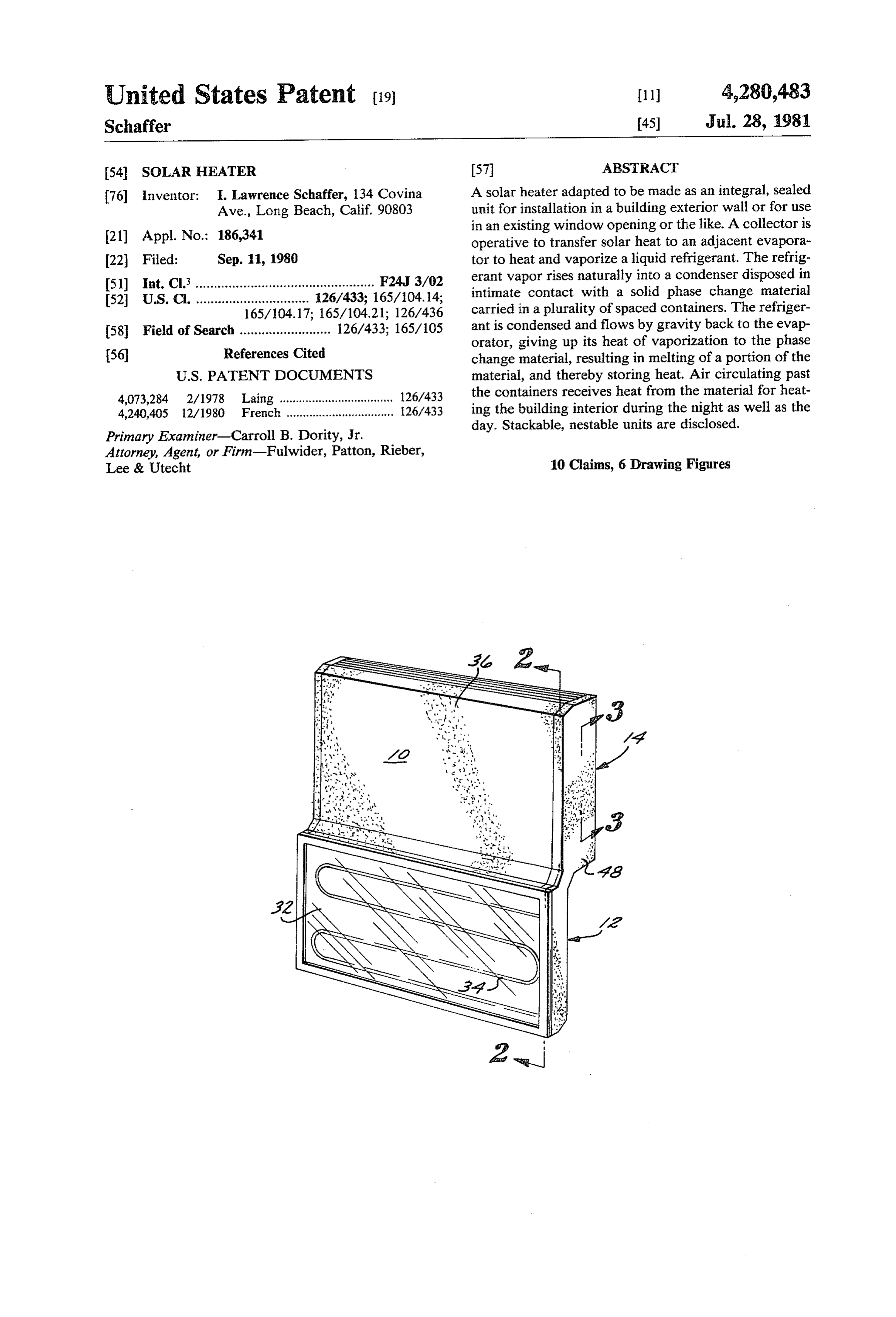
54 SOLAR HEATER 57 ABSTRACT 76 Inventor: I. Lawrence Schaffer, 134 Covina A solar heater adapted to be made as an integral, sealed Ave., Long Beach, Calif. 90803 unit for installation in a building exterior wall or for use in an existing window opening or the like. A collector is (21) Appl. No.: 186,341 operative to transfer solar heat to an adjacent evapora 22 Filed: Sep. 11, 1980 tor to heat and vaporize a liquid refrigerant. The refrig I51) Int. Cl. ................................................. F24J 3/02 erant vapor rises naturally into a condenser disposed in 52 U.S. C. ............................... 126/433; 165/104.14; intimate contact with a solid phase change material 165/104.17; 165/104.21; 126/436 carried in a plurality of spaced containers. The refriger 58 Field of Search ......................... 126/433; 165/105 ant is condensed and flows by gravity back to the evap orator, giving up its heat of vaporization to the phase (56) References Cited change material, resulting in melting of a portion of the
4,073,284 2/1978 Laing ................................... 126/433 the containers receives heat from the material for heat 4,240,405 12/1980 French. ................................. 26/433 ing the building interior during the night as well as the day. Stackable, nestable units are disclosed.
Primary Examiner-Carroll B. Dority, Jr.
Attorney, Agent, or Firm-Fulwider, Patton, Rieber,
Lee & Utecht 10 Claims, 6 Drawing Figures
Page 2
Drawing sheet — no readable text.
Page 3
refrigerant will flow downwardly into the evaporator
SOLAR HEATER under the influence of gravity. When the evaporator is no longer receiving solar heat, the liquid refrigerant
BACKGROUND OF THE INVENTION collecting in the evaporator prevents further circulation i. Field of the Invention of refrigerant, thereby preventing an unwanted with The present invention relates to solar heaters, and drawal of heat from the phase change material and particularly to solar heaters of the type utilizing a va escape to the outside through the evaporator and col porizable refrigerant to effect heat transfer to a heat lector.
storage means. The present solar heater is typically self-contained O and hermetically sealed for easy and rapid installation 2. Description of the Prior Art
Conventional solar heating systems can be broadly into new construction or into an existing window open categorized as either passive or active. A passive system ing, for example. In one embodiment the heater config is effective to collect heat during the day to heat the uration permits a plurality of heaters to be stacked in building interior, but during the night an unacceptable 15 superposed relation in a vertically elongated opening in heat loss occurs unless the collector air space is manu a building wall.
ally or automatically covered with insulation during the No pumps or fans are required for circulation of air or night. This introduces an undesired system complexity. refrigerant. However, if desired, particularly where in addition, the enclosed air spaces in a typical passive stacked units are involved, a fan can be utilized to facili system become uncomfortably hot during the day in 20 tate air circulation past the heat storage containers. order to store enough heat for significant heating at Other objects and features of the invention will be night. come apparent from consideration of the following Active heating systems require circulation of fluids description taken in connection with the accompanying such as air, water, ethylene glycol and the like, through drawings.
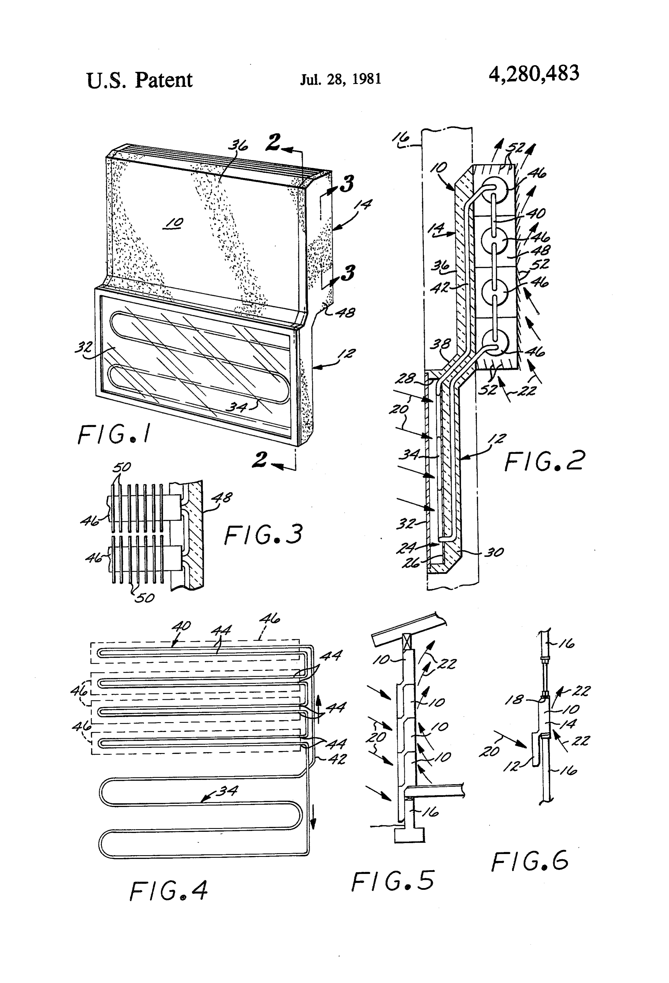
the collector portion of the system during the day. This makes the system complex and expensive since recircu 25 BRIEF DESCRIPTION OF THE DRAWINGS lation pumps or fans are required. In addition, associ FIG. is a perspective view of a solar heater accord ated controls are required to halt such fluid circulation ing to the present invention;
at night. The added components and moving parts in such a system typically result in a much shorter service of FIG. FIG.
2 is an enlarged view taken along the line 2-2
life compared to passive heating systems. FIG. 3 is an enlarged detail view taken along the line An interesting variation on the foregoing systems is 3-3 of FIG. ;
an apparatus disclosed in U.S. Pat. No. 4,073,284, issued FIG. 4 is a generally diagrammatic view of the inter Feb. 14, 1978, and entitled "Process and Device for connected evaporator and
Utilizing Meteorlogical Radiations'. This system uses a direction of refrigerant flow;condensor, illustrating the heat storage material to store energy in the form of 35 FIG. 5 is a generally diagrammatic side elevational latent heat rather than sensible heat, thereby tending to avoid some of the problems of passive systems. A heat view of a plurality of the solar heaters arranged in su storage material is used whose temperature of crystalli perposed, stacked relation; and zation coincides with the desired process temperature. FIG. 6 is a diagrammatic side elevational view of a Heat is stored in the material by changing its phase from 40 single solar heater mounted within a window opening. solid to liquid at a predetermined process temperature. DESCRIPTION OF THE PREFERRED However, the system utilizes wicking to effect move EMBODIMENT ment of refrigerant in opposition to the force of gravity, and this results in a relatively complex structure. An Referring now to the drawings, there is illustrated a important consideration in a suitable solar heater is 45 solar heater 10 according to the present invention. As simplicity of construction to reduce initial cost and will be seen, the heater 0 is described in connection prolong service life. with the heating of a building interior, such as a house interior. In one embodiment, the heater is configured
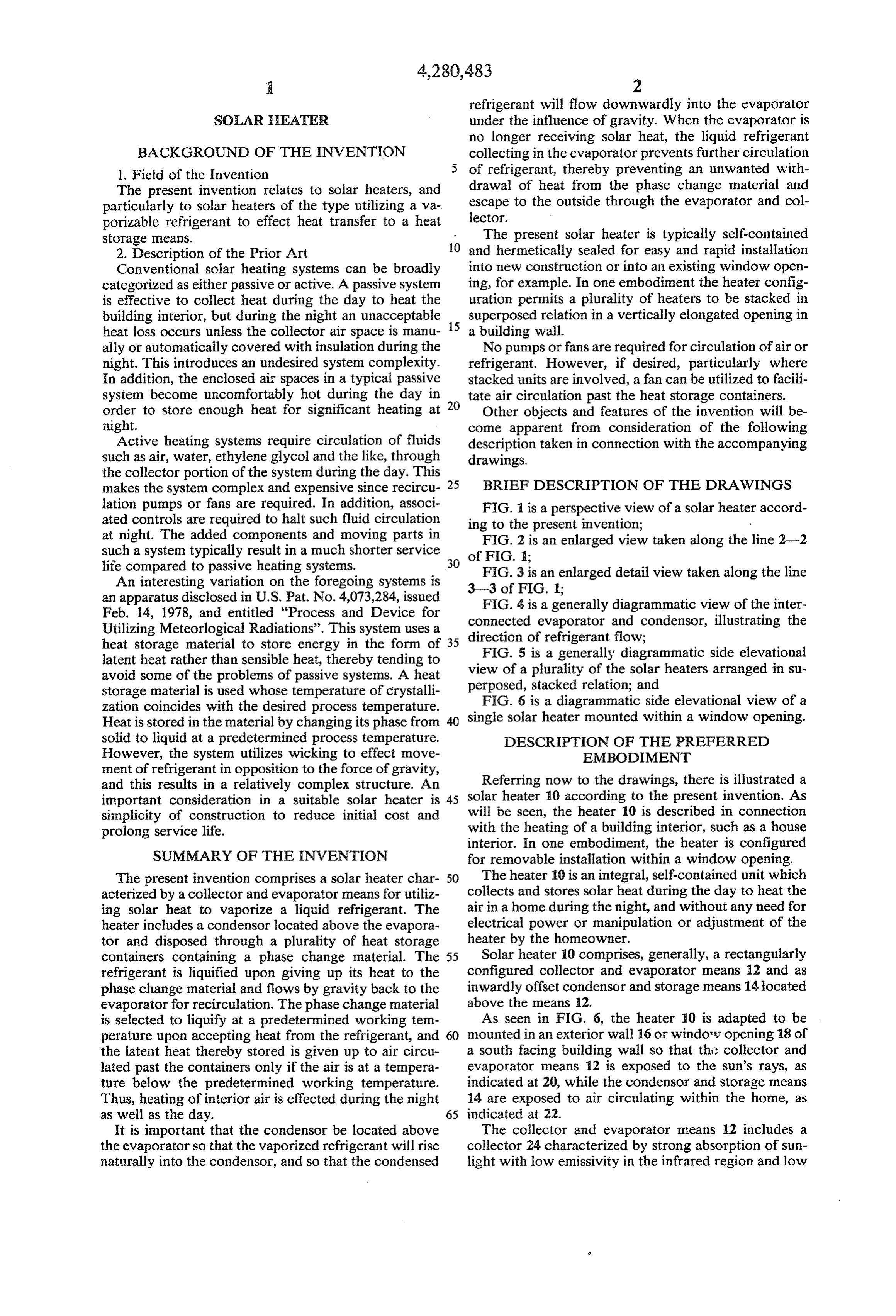
SUMMARY OF THE INVENTION for removable installation within a window opening. The present invention comprises a solar heater char 50 The heater 0 is an integral, self-contained unit which acterized by a collector and evaporator means for utiliz collects and stores solar heat during the day to heat the ing solar heat to vaporize a liquid refrigerant. The air in a home during the night, and without any need for heater includes a condensor located above the evapora electrical power or manipulation or adjustment of the tor and disposed through a plurality of heat storage heater by the homeowner.
containers containing a phase change material. The 55 Solar heater 10 comprises, generally, a rectangularly refrigerant is liquified upon giving up its heat to the configured collector and evaporator means 12 and as phase change material and flows by gravity back to the inwardly offset condensor and storage means 14 located evaporator for recirculation. The phase change material above the means 12.
is selected to liquify at a predetermined working ten As seen in FIG. 6, the heater 10 is adapted to be perature upon accepting heat from the refrigerant, and 50 mounted in an exterior wall 6 or window opening 18 of the latent heat thereby stored is given up to air circu a south facing building wall so that this collector and lated past the containers only if the air is at a tempera evaporator means 12 is exposed to the sun's rays, as ture below the predetermined working temperature. indicated at 20, while the condensor and storage means Thus, heating of interior air is effected during the night 14 are exposed to air circulating within the home, as as well as the day. 65 indicated at 22.
It is important that the condensor be located above The collector and evaporator means 12 includes a the evaporator so that the vaporized refrigerant will rise collector 24 characterized by strong absorption of sun naturally into the condensor, and so that the condensed light with low emissivity in the infrared region and low
Page 4
convective losses. Preferably the collector 24 includes a 44 to the phase change material, and not via any inter heat conductive absorber sheet 26 having a black outer mediate medium such as air, thereby avoiding undesir surface for maximum heat absorption. The sheet 26 is ably high temperatures in the condensor area. The mounted in a cavity provided in a rectangular block 30 phase change material is in a solid state below a prede made of suitable heat insulating material. The cavity 28 termined working temperature, such as approximately is covered by a sheet 32 of material such as glass which 81 F., for example, whereby heated refrigerant in a is transparent to the sun's rays, but which is substan vapor state in the condensor 40 will melt or liquify a tially opaque to long wave radiation. As is well known, portion of the phase change material without raising the the result of this arrangement is to develop or collect temperature surrounding the storage containers 46 to an heat in the collector cavity 28. O uncomfortable level. The stored heat is latent heat, and An evaporator 34 of serpentine tubular construction is released only when the working temperature of the is brazed or otherwise attached to the absorber sheet 26 surrounding environment drops to a temperature below for good heat transfer, and its horizontally oriented runs the predetermined working temperature. A number of are slightly inclined so that any liquid refrigerant in phase change materials suitable for this purpose are such runs tends to flow downwardly under the influ 15 available on the market, one form being calcium chlo ence of gravity. The tubes of the evaporator 34 gener ride hexahydrate (CaCl2.6H2O) which is commercially ally lie in a vertical plane, although the plane of the available as "XFS-43076' from the Dow Chemical evaporator tubes may be sloped away from the sun, if Company.
desired, to achieve improved solar energy collection. Each of the heat storage containers 46 preferably As alternatives to the serpentine series tubing arrange 20 mounts a plurality of annular heat conducting fins 50 ment shown, the evaporator may employ parallel flow which are uniformly spaced apart along the length of paths or a series/parallel combination thereof. each container.
The refrigerant is preferably a low vapor pressure Suitable louvers 52 may be mounted between the end substance such as "Freon 11’ or "Freon 113', manufac panels 48 at the top, bottom and back of the condensor tured by the DuPont Company. Such a refrigerant va 25 and storage means 14 to facilitate circulation of air past porizes in the evaporator 34 as the temperature in the the containers 46 and fins 50 along the paths generally cavity 28 mounts during sunny, daylight conditions. indicated in FIG. 2.
The condensor and storage means 14 comprises a In operation the solar heater 10 is vertically arranged block 36 made of heat insulating material which is in within the wall 6 or window opening 18 on the south wardly offset relative to the lower block 30, being con 30 side of the building. During daylight hours the sun's nected to the block 30 by an integral upwardly and rays impinge upon the collector sheet 26 and develop inwardly inclined intermediate block 38, as best seen in solar heat in the cavity 28. The collected heat is trans FIG. 2. ferred to the liquid refrigerant within the evaporator 34, The means 14 includes a tubular condensor 40 whose resulting in vaporization of the refrigerant. The refrig serpentine series connected runs are fluid coupled to the 35 erant vapor rises naturally within the vertical run 42 evaporator 34 by a vertical run 42, as best seen in FIG. and passes into the condensor runs 44. The relatively 4. The run 42 is connected to the upper run of the upper hot refrigerant vapor condenses and transfers its heat to pair of a plurality of pairs of horizontal runs 44. Each the solid phase change material within the containers pair of runs extends into and out of a cylindrical, hori 46. The condensed refrigerant flows by gravity back to Zontally elongated heat storage container 46, and all of 40 the evaporator 34 to repeat the cycle. the pairs of horizontal runs 44 are interconnected as A quantity of the phase change material liquifies, illustrated in FIG. 4, and all generally lie in a vertical according to the degree of heat exchange, and this heat plane inwardly offset relative to the vertical plane is retained as latent heat unless the air circulating past within which the evaporator tubes lie. The horizontally the heat exchange fins 50 is at a temperature below the oriented condensor runs 44 are sloped slightly to facili 45 predetermined working temperature, such as at night. tate gravity drainage of liquid refrigerant. As alterna When this occurs air circulating past the containers 46 tives to the serpentine series tubing arrangement shown, and fins 50 warms the room air through natural convec the condensor may employ parallel flow paths or a tion, although a circulating fan (not shown) could be series/parallel combination, thereof. employed if desired. This continues until all of the phase As seen in FIGS. 2 and 3, the vertical run 42 is dis 50 change material has resolidified. posed through the insulating material of the block 36. Excessive air heating during periods of complete Similarly, the short vertical runs connecting the runs 44 melting or liquification of the phase change material can are disposed within end panels 48 made of heat insulat be avoided, if desired, by closing the louvers 52 or by ing material and overlying and covering the ends of the employing a thermostatic valve (not shown) to block means 12 and 14, as seen in FIG. I. 55 refrigerant circulation. System overpressure is avoided The upper portions of the panels 48 project rear by virtue of the use of the low vapor pressure refriger wardly of the insulating block 36 and structurally sup ant previously mentioned, and by allowing sufficient port the ends of the plurality of heat storage containers volume within the storage containers 46 to accommo 46. The containers 46 are arranged in vertically spaced date phase change material expansion. apart relation and also in spaced relation to the upper 60 During the night, or whenever the outside tempera block 36 to facilitate air circulation therein, as will be ture falls below the temperature existing in the cavity See. 28, refrigerant evaporation or vaporization ceases and Each container 46 is liquid tight and is filled leaving the resulting liquid refrigerant flows into and fills the volume for expansion, with a suitable phase change tubular evaporator 34. This blocks the flow of any re material (not shown) within which the horizontal con 65 frigerant vapor through the condensor 40 and prevents densor runs 44 are embedded in intimate heat exchange heat from being transported from the condensor and relation. Fins (not shown) may be employed to facilitate storage means 14 to the collector and evaporator means heat transfer. Heat transfer is thus directly from the runs 12 where it would undesirably be dissipated to the
Page 5
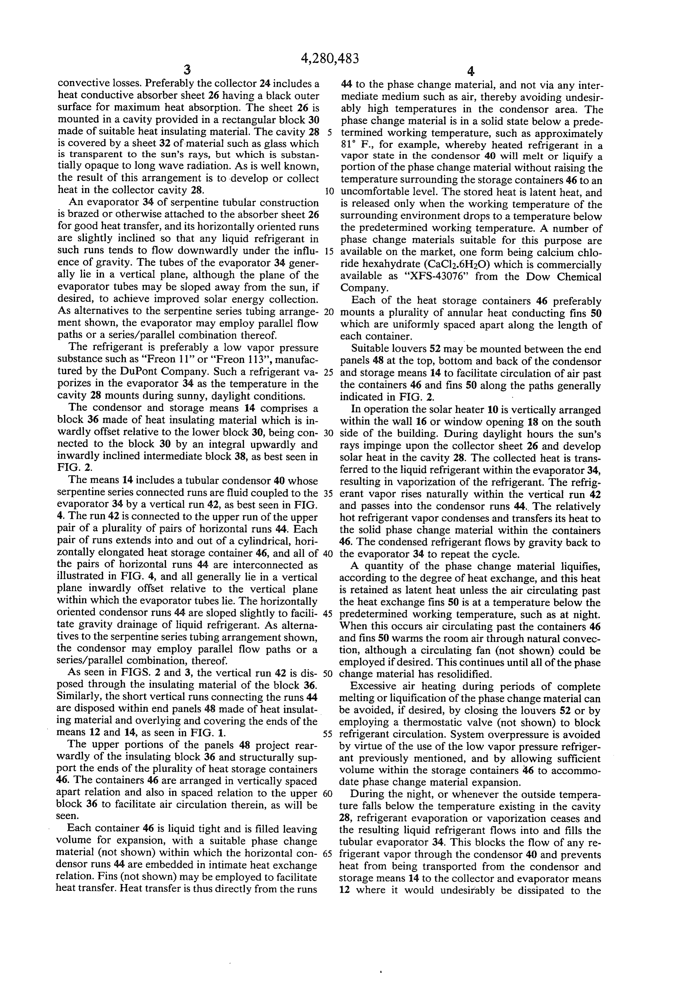
colder environment existing exteriorly of the evapora upon receipt of heat from said condensor whereby tor 34. Instead, the latent heat stored in the phase said heat may be released to a surrounding environ change material within the containers 46 is conserved ment colder than said working temperature during and continues to warm the house air by natural convec a phase change of said material from a liquid to a tion of the house air through the louvers 52, such warm- 5 solid state, and whereby the cooled, liquid refriger ing continuing until all of the phase change material is ant is enabled to flow by gravity into said evapora again in a solid state. Conservation of heat is enhanced tor, said liquid refrigerant in said evaporator ob by the presence of the insulating material of the blocks structing continued circulation of refrigerant 30, 36 and 38. through said condensor and said evaporator in the In a typical application, the solar heater is fully pre- 10 absence of collection of solar heat by said collector charged with refrigerant and phase change material thereby to reduce heat loss through said evapora prior to installation. Proper sizing of the storage con tor during the night.
tainers 46 and other heat transfer elements maintains the 2. A solar heater according to claim 1 and including phase change material in a partially solid, partially liq heat insulation upon the interiorly located side of said uid condition to provide a relatively constant tempera collector and evaporator means, and further including ture for heating of room air. heat insulation upon the exteriorly located side of said The offset configuration of the means 12 and 14 al condensor and storage means.
lows stacking of identical heaters 10 in superposed rela 3. A solar heater according to claim 1 wherein said tion, as seen in FIG. 5, whereby the heaters 10 can form phase change material is included in a plurality of con part of the building wall. With this arrangement an air 20 tainers, and the tubing of said condensor extends circulation fan (not shown) and suitable ducting (not through said containers, said containers being spaced shown) could be employed to more precisely control apart whereby air may circulate naturally past said the flow of air past the storage containers 46. containers for heating the surrounding environment. From the foregoing it will be seen that there has been 4. A solar heater according to claim 3 and including provided a self-contained solar heater 10 which can be 25 heat transfer fins upon the exteriors of said containers. precharged with refrigerant and phase change material 5. A solar heater according to claim 1 wherein said for ready installation. It stores solar heat collected dur collector and evaporator means and said condensor and ing the day and makes it available to heat the house storage means constitute an integral, sealed unit rectan during the evening or whenever interior air tempera gularly configured for installation in a building window tures drop below a predetermined level. There is no 30 opening, said condensor and storage means being need for any electrical power nor any need for adjust adapted for engagement at its upper and lower termini ment of the heater under most conditions. by the structure defining the upper and lower margins The collection of solar energy is efficient since the of said window opening, said collector and evaporator refrigerant is circulated only when temperature condi means being outwardly offset from said condensor and tions are favorable for heat retention. Collected solar 35 storage heat is transported through an insulation barrier for rior below means for location adjacent the building exte storage in the phase change material, and heat leakage said window opening. back through that barrier is prevented. The collected collector 6. A solar heater according to claim 1 wherein said solar heat is stored directly in the phase change mate relative toand evaporator means are outwardly offset rial, without any intermediate and possibly excessive plurality of saidcondensor said solar and storage means whereby a heaters can be stacked in nested, heating of house air in the condensor area. The thermal superposed relation to form a part of a building wall, the storage containers 46 are not exposed to direct sunlight interior sides of all the collector and evaporator means and therefore need not be constructed of ultraviolet resistant materials. The modular shape of the heater 10 except the bottom solar heater resting, respectively, also allows stacking to efficiently utilize both exterior 45 against eaS.
the exterior sides of the condensor and storage and interior wall spaces, and the heater can be adapted 7. A solar heater according to claim 1 wherein the to fit standard window openings.
Various modifications and changes may be made with rator and saidoriented horizontally rows of the tubing of said evapo regard to the foregoing detailed description without flow of liquid refrigerantare condensor
sloped to facilitate gravity said evaporator.
departing from the spirit of the invention. 50 8. A solar heater according to claim 1 wherein the
I claim:
1. A solar heater comprising: tubing of said evaporator is generally oriented in a first vertical plane, and the tubing collector and evaporator means including a collector ally oriented in a second vertical plane. of said condensor is gener for exposure to the sun to collect solar heat, and further including a tubular evaporator in heat ex 55 9. and A solar heater according to claim 8 wherein said change relation to said collector and having liquid first second vertical planes are vertically offset to refrigerant therein adapted to be vaporized upon facilitate vertical stacking and nesting of a plurality of receipt of solar heat from said collector; and said solar units.
condensor and storage means located above said col 10. A solar heater comprising: lector and evaporator means and including a tubu- 60 rectangularly configured collector and evaporator lar condensor in fluid communication with said means for location below a building window open evaporator for receiving vapor refrigerant rising ing adjacent the building exterior, and including a naturally from said evaporator upon being heated collector for exposure to the sun to collect solar by said solar heat, said condensor and storage heat, and further including a generally vertically means further including solid phase change mate 65 disposed tubular evaporator in heat exchange rela rial within which said condensor is embedded in tion to said collector and having liquid refrigerant heat exchange relation, said material being adapted therein adapted to be vaporized upon receipt of to liquify at a predetermined working temperature solar heat from said collector; and
Page 6
rectangularly configured condensor and storage nied by a phase change of said material from a means located above and interiorly offset relative liquid to a solid state, said heat may be released to to said collector and evaporator means to fit within air colder than said working temperature and said window opening, and including a generally which is flowing past said containers, and whereby vertically disposed tubular condensor in fluid com the cooled, liquid refrigerant is enabled to flow by munication with said evaporator for receiving gravity into said evaporator, said liquid refrigerant vapor refrigerant rising naturally from said evapo in said evaporator obstructing continued circula rator upon being heated by said solar heat, said tion of refrigerant through said condensor and said condensor and storage means further including a evaporator in the absence of collection of solar plurality of spaced apart containers containing O heat by said collector thereby to reduce heat loss solid phase change material and through which through said evaporator during the night, the exte said tubular condensor extends in heat exchange riorly facing portion of said condensor and storage relation, said material being adapted to liquify at a means and the interiorly facing portion of said predetermined working temperature upon receipt evaporator being insulated.
of heat from said condensor whereby, accompa 15 t k k
Provenance
- Collection
- Cited prior art
- Original PDF
- patentimages.storage.googleapis.com →
- Filed
- 1980-09-11
- Pages
- 6
- Method
- pdftotext (the PDF's own text layer) + pdftoppm 300dpi page scans
- Source
- Google Patents bibliographic record
- Granted
- 1981-07-28
- Inventors
- I. Lawrence Schaffer
- Transcribed from
- patentimages.storage.googleapis.com →