patent · US4165963
Hot water heater burner assembly
28 August 1979
Page 1 — bibliographic record
United States Patent (19) (11) 4,165,963 Nozaki 45) Aug. 28, 1979 54 HOT WATER HEATER BURNER ASSEMBLY 2,985,233 5/1961 Stellmach ............................. 431/355 3,124,108 3/1964 Wenczl ...... ... 122/17 (75) Inventor: Michio B. Nozaki, LaGrange, Ill. 3,324,925 6/1967 McLaren .............................. 239/434 (73) Assignee: Rheem Manufacturing Company, FOREIGN PATENT DOCUMENTS New York, N.Y. 640037 4/1962 Canada ..................................... 431/355 21 Appl. No.: 845,780 Primary Examiner-Carroll B. Dority, Jr. 22 Filed: Oct. 26, 1977 Attorney, Agent, or Firm-Allegretti, Newitt, Witcoff & McAndrews
Related U.S. Application Data
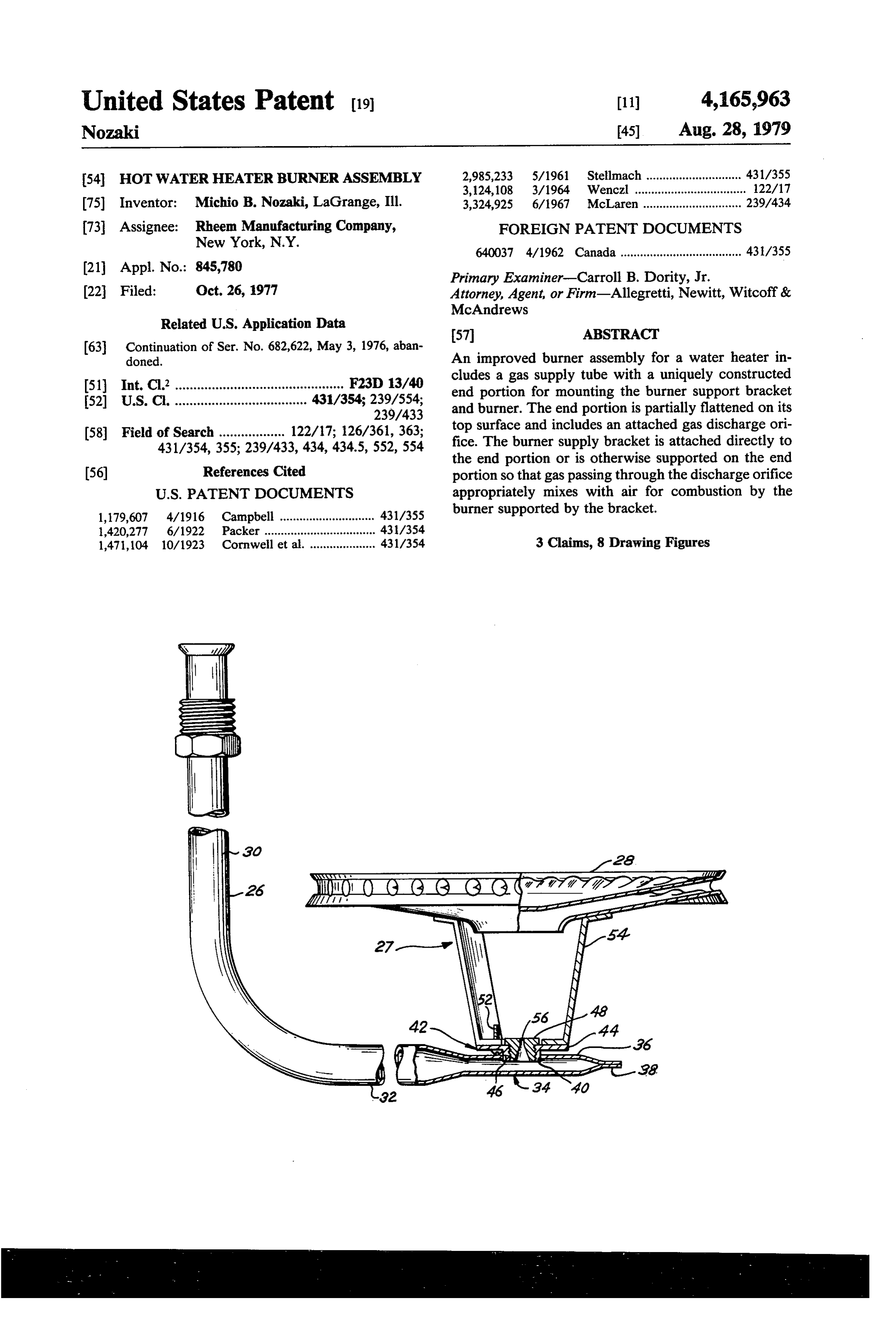
doned. An improved burner assembly for a water heater in cludes a gas supply tube with a uniquely constructed (51) Int. Cl’.............................................. F23D 13/40 end portion for mounting the burner support bracket 52) U.S. C. .................................... 431/354; 239/554; and burner. The end portion is partially flattened on its
(58) Field of Search .................. 122/17; 126/361, 363; top surface and includes an attached gas discharge ori 431/354, 355; 239/433, 434, 434.5, 552, 554 fice. The burner supply bracket is attached directly to the end portion or is otherwise supported on the end (56) References Cited portion so that gas passing through the discharge orifice
1,179,607 4/1916 Campbell ............................. 431/355 burner supported by the bracket.
1,420,277 6/1922 Packer ........... ... 43/354 1,471,104 10/1923 Cornwell et al. .................... 431/354 3 Claims, 8 Drawing Figures
Page 2
Drawing sheet — no readable text.
Page 3
Drawing sheet — no readable text.
Page 4
Thus, it is an object of the present invention to pro
HOT WATER HEATER BURNER ASSEMBLY vide a burner assembly having an improved burner supply tube.
This is a continuation of application Ser. No. 682,622 It is a further object of the present invention to pro filed May 3, 1976 and now abandoned. vide a burner supply tube which minimizes the height of
BACKGROUND OF THE INVENTION
the total burner assembly resulting from the burner supply tube and orifice configuration.
This invention relates to an improved burner con Still another object of the present invention is to struction for water heaters and more particularly to the 10 provide a burner supply pipe wherein a gas orifice is construction of the burner supply pipe for the burner positioned in a lateral or side portion of the burner construction. supply tube for discharge into a burner. The basic construction of a domestic gas hot water A further object of the present invention is to provide heater includes a cylindrical tank for the water with a asupplied flat sheet metal burner for a water heater which is concentric flue pipe projecting through the tank to the 15 air while with an adequate amount of gas and primary simultaneously being incorporated as part of a bottom of the tank. A burner unit is positioned adjacent burner assembly having a low profile. the bottom of the tank so that burner combustion prod ucts will flow upwardly through the flue pipe and ap of labor, materials and of
Still a further object the invention is to reduce cost the number of parts in a burner propriate exhaust passages to the atmosphere. The en assembly relative to conventional heater burner assem tire assembly is surrounded by insulation. 20 blies.
The burner is generally supported on a burner supply These and other objects, advantages and features of pipe by means of special bracket assembly. Typically, the invention will be set forth in greater detail in the burner supply pipes are tubular and include a horizontal description which follows. run along the bottom side of the tank. This horizontal run makes a vertical upward turn and generally termi 25 BRIEF DESCRIPTION OF THE DRAWINGS nates with a gas orifice or nozzle. A bracket assembly is In the detailed description which follows, reference mounted over the gas orifice or nozzle to support the will be made to the drawings comprised of the follow burner. Gas then ejects from the orifice or nozzle for ing FIGURES:
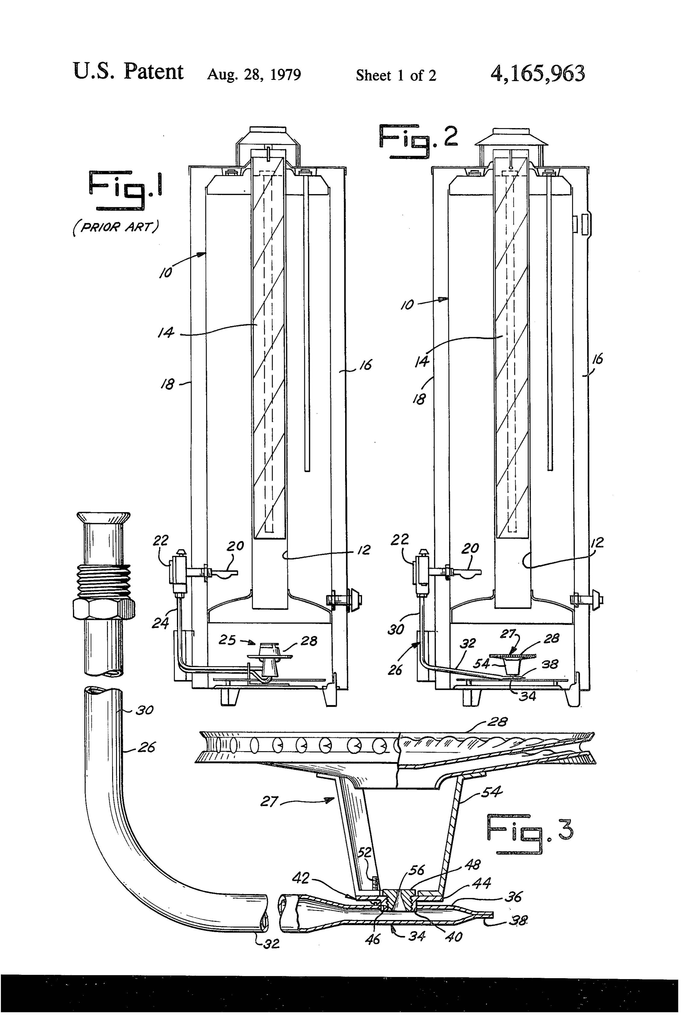
mixing with air. The mixture flows upwardly to the FIG. 1 is a cross-sectional view of a typical prior art burner for combustion so that the water in the tank may 30 water heater including a burner assembly for the heater; be heated. FIG. 2 is a cross-sectional view of a typical water In order to conserve space within the water heater heater including the improved burner assembly of the tank assembly, and reduce the height of the total assem present invention;
bly as much as possible, it is desirable to minimize the FIG. 3 is a side view of the improved burner assem vertical height of the burner assembly, including the 35 bly of the present invention;
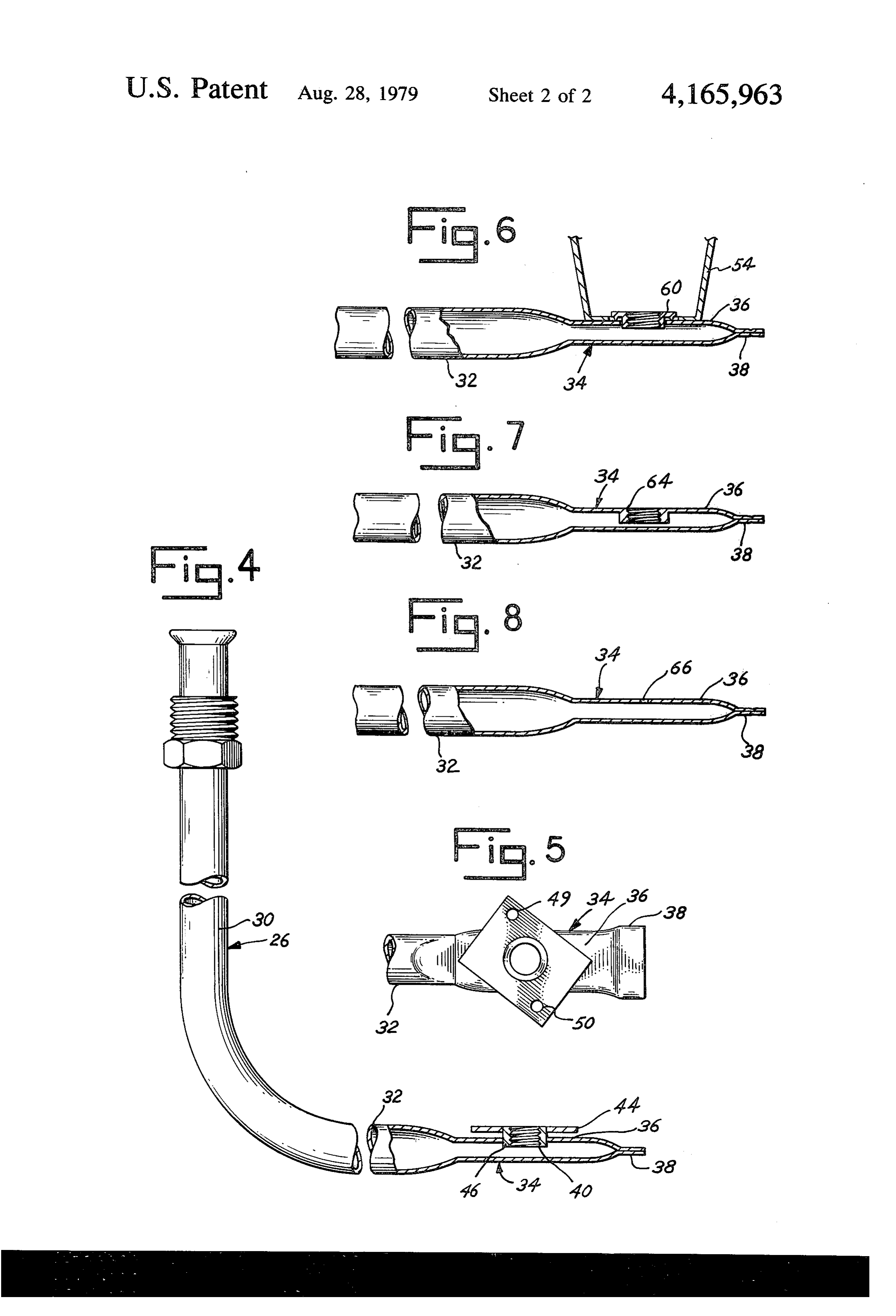
burner supply pipe. Heretofore, because of the necessity FIG. 4 is a side view of the burner supply tube for the for directing the burner supply orifice in a vertical di assembly of FIG. 3;
rection upward toward the burner, the profile of the FIG. 5 is a top view of the end portion of the burner burner assembly has not been sufficiently flat to accom supply tube of FIG. 4;
plish the objective of reducing the height of the heater. FIG. 6 is an enlarged cross-sectional view of the end Since the burner must be spaced an adequate vertical portion of the burner supply tube of an alternate em distance above the orifice to provide adequate aspira bodiment of the present invention;
tion for primary air and complete combustion at the FIG. 7 is an enlarged cross-sectional view of an end burner, the burner profile cannot be decreased by plac 45 portion of the burner supply tube of another embodi ing the burner closer to the gas discharge orifice. The ment of the present invention; and FIG. 8 is an enlarged cross-sectional view of the end present invention, however, provides an improved portion of a burner supply tube of a third embodiment burner supply pipe structure which decreases the of the invention.
burner assembly profile relative to prior art burner assemblies. DESCRIPTION OF THE PREFERRED
SUMMARY OF THE INVENTION EMBODIMENT
The present invention comprises an improved burner FIG. 1 illustrates the general construction of a typical assembly for a water heater of the type which includes hot The water heater with a prior art gas burner assembly.
heater includes a water tank 10 which is generally a horizontal supply tube for providing combustible gas 55 annular to a burner unit. The supply tube of the present inven gallons, in shape and glass lined with a capacity of 100 tion is generally cylindrical and terminates with an end annular crossexample.
for The tank 10 is constructed with an section to define a central flue chamber or portion flattened at least on its top side to a dimension of flue 12. A baffle 14 is mounted in the flue 12 to augment approximately one-half the diameter of the tube. The extreme end of the tube is then sealed. A gas orifice may 60 circulation through. The of the hot combustion products there heater tank 12 is surrounded by insulation be directly incorporated in the flattened top side of the 16 and is supported within a jacket 18. A thermostat 20 supply tube or it may be attached thereto. A mounting projects into the tank and controls a valve mechanism bracket is also attached to the flat top side of the end 22 linked with a gas burner supply tube 24. portion of the supply tube for support of the burner. In The gas burner supply tube 24 comprises a portion of this manner, gas discharging from the end portion of the 65 a burner assembly 25. In general, the burner assembly supply tube passes through the orifice in the top side of 25 includes a burner 28 positioned on the bottom side of the supply tube in an upward vertical direction for the tank 10 so that fuel introduced through the tube 24 mixing with air and combustion at the burner. may properly mix or aspirate with air for combustion
Page 5
and heating of water within the tank 10. The present nated. The lateral orifice design of the burner supply invention relates, in particular, to the construction of an tube 26 permits maximization of the distance between improved burner assembly distinct from the typical the burner 28 and the gas orifice and minimization of the prior art assembly 25 in FIG. A. overall height of the burner assembly. Total aspiration FIGS. 2 and 3 illustrate the improved burner assem and complete combustion of the gas-air mixture is bly 27 of the present invention. A burner supply tube 26 thereby insured. This feature is emphasized by a com includes a vertical run 30 connected with a horizontal parison of FIGS. 1 and 2. In FIG. 2, the assembly 27 has run 32 terminating with an end portion 34. The end replaced the prior art assembly 25 shown in FIG. 1. The portion 34 of tube 26 is flattened, for example, by a assembly 27 has additional volume between the burner forging or stamping operation, to define a burner supply 10 28 and tank 10. Thus, combustion is more likely to be pipe platform 36 which is generally flat. The end of the complete. Maximum heat transfer occurs. These advan supply tube 26 is sealed by closing end 38 of tube 26 and tages are effected without changing the size or shape of welding the end portion as illustrated in FIGS. 2 and 3. the total water heater assembly.
Platform 36 includes an opening 40 which may be The flat platform 36 may also be used as a reference drilled, punched or otherwise formed. A separate fitting 15 base for attachment of the burner in true alignment with 42 is then welded or brazed in the opening 40. Fitting 42 the orifice opening. This substantially eliminates elabo includes a flat planar portion or plate 44 and an inter rate assembly tooling required in many prior art burner nally threaded stub 46 extending through plate 44. Stub assemblies. Thus, while in the foregoing there has been 46 is threaded to receive a burner orifice fitting or mem set forth preferred embodiments of the present inven ber 48. 20 tion, it is to be understood that the invention shall be FIG. 4 and FIG. 5 illustrate, in greater detail, the limited only by the following claims and their equiva construction of the end portion 34 and fitting 42. Note lents.
that the piate 44 is generally rectangular in shape as What is claimed is:
illustrated in FIG. 4 and includes screw openings 49 and a. An improved burner construction for a water 50 which fall outside of the projection of the end por 25 heater comprising, in combination:
tion 34. In this manner, burner mounting screws as at 52 a burner supply tube having a first diameter, said in FIG.3 may be inserted through the openings 49 and supply tube including a first horizontal run termi 50 to cooperate and attach to a burner bracket 54 which nating with an end portion, said end portion being supports the burner 28. The burner bracket 54 serves to 30 flattened to a dimension approximately one-half the space the burner 28 an adequate distance from an orifice diameter of the tube and sealed at the extreme end 56 in FIG. 3 in the burner orifice fitting 48 thereby of the tube to define a flat top surface of the end insuring complete primary air aspiration of fuel from portion;
burner supply tube 26.
FIGS. 6 through 8 illustrate variations of the supply 35 a gas-flow portion;
passage in the flat top surface of the end tube construction for the improved burner assembly of a bracket;
the present invention. In FIG. 6, burner bracket 54 is a burner attached to the bracket; welded or brazed directly to the flat platform 36 of end means for attaching the bracket over the gas-flow portion 34. An orifice spud 60 is then welded or brazed flush with the platform 36 and a fitting (not shown) for 40 saidpassage;
means for attaching the bracket comprising a the orifice may be threaded into the spud 60. horizontal, planar platform surface member with a In FIG. 7, the end portion 34 of the tube 26 is bored fitting projecting from the surface member through by hot spinning, for example, to define an opening 64 said passage, said fitting including a burner orifice which is subsequently tapped. An orifice spud or fitting through the platform member, said bracket remov of the type illustrated in FIG. 6 may then be threaded 45 ably attached by fasteners to said platform member into the opening 64. The burner bracket 54, though not whereby the burner is maintained in alignment shown in FIG. 7, would be welded directly to the plat with the passage and orifice to receive a mixture of form 36.
In FIG. 8, the burner bracket 54, though again not fuel and air for combustion by the burner. shown, would be welded directly to the platform 36 of 2. The burner construction of claim 1 wherein said end portion 34. Also, the gas orifice is defined by a small 50 fitting includes an internally threaded stub projecting drilled opening 66 in the flat platform 36 of end portion from the platform member, said stub being welded to 34. This would eliminate the need for any spud and the burner supply tube and also including an orifice separately defined orifice. fitting which is screw fitted in the threaded stub. With the present invention, the number of parts rela 3. The improved construction of claim 1 wherein said tive to prior art burner assemblies has been minimized gas-flow passage is defined by a drilled opening of pre or reduced. Moreover, each part can be made by simple determined orifice size in the flat surface of said end sheet metal stamping and tube forming operations. Ex portion. s :k : : pensive machining operations are substantially elimi
Provenance
- Collection
- Cited prior art
- Original PDF
- patentimages.storage.googleapis.com →
- Filed
- 1977-10-26
- Pages
- 5
- Method
- pdftotext (the PDF's own text layer) + pdftoppm 300dpi page scans
- Source
- Google Patents bibliographic record
- Granted
- 1979-08-28
- Inventors
- Michio B. Nozaki; Rheem Manufacturing Co
- Transcribed from
- patentimages.storage.googleapis.com →