patent · US4264362
Supercorroding galvanic cell alloys for generation of heat and gas
28 April 1981
Page 1 — bibliographic record
United States Patent (19) 11 4,264,362 Sergev et al. 45 Apr. 28, 1981 54 SUPERCORRODING GALVANIC CELL 56 References Cited ALLOYS FOR GENERATION OF HEAT AND U.S. PATENT DOCUMENTS GAS 3,591,362 7/1971 Benjamin ......................... 428/570 X 75 Inventors: Sergius S. Sergev; Stanley A. Black; 3,942,511 3/1976 Black et al. ... ... 252/88 T James F. Jenkins, all of Ventura, 3,993,577 11/1976 Black et al. ... ... .252/88 Calif. 4,017,414 4/1977 Black et al. .......................... 252/88 73) Assignee: The United States of America as Primary Examiner-Richard E. Schafer represented by the Secretary of the Attorney, Agent, or Firm-Richard S. Sciascia; Joseph Navy, Washington, D.C. M. St. Ammand
Supercorroding magnesium alloys that operate like
Related U.S. Application Data r galvanic cells and react rapidly and predictably with 63 Continuation-in-part of Ser. No. 855,035, Nov. 25, seawater to produce heat and hydrogen gas. The alloys 1977, abandoned. are formed by a mechanical process that bonds magne sium and noble metal powder particles together in a 51) Int. Cl........................... C22B 1/05; C09K3/00; strong electrical and mechanical bond. The alloy pow C01B 3/08; B22F 1/00 ders can be compacted and sintered to form barstock, 52 U.S. C. ........................................ 75/243; 75/245; etc., suitable for making self-destructing corroding 75/246; 75/249; 252/188; 252/188.3 R; links.
252/188.3; 423/657, 658; 75/249, 243, 246, 245 20 Claims, 22 Drawing Figures
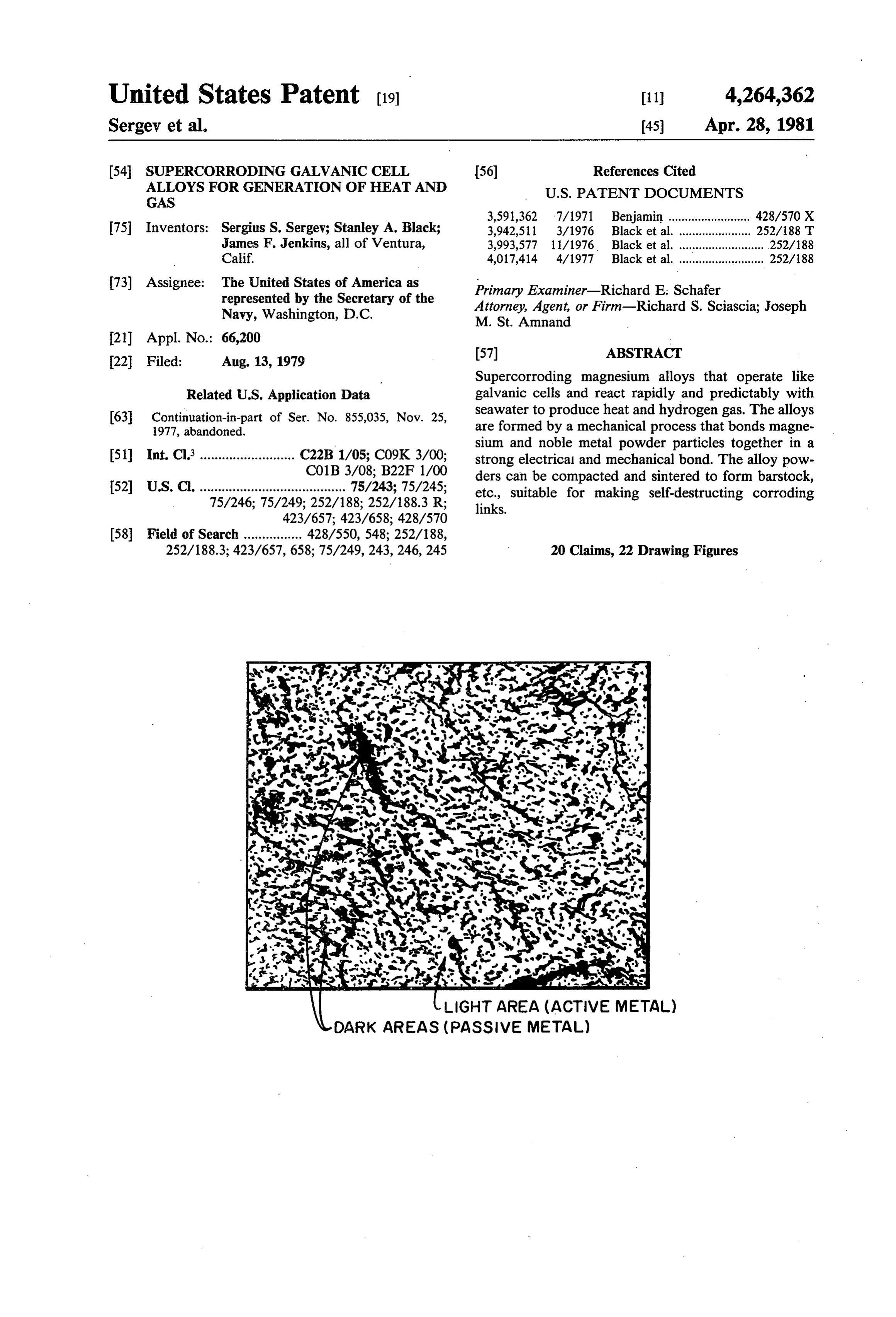
LIGHT AREA (ACTIVE METAL)
DARK AREAS (PASSIVE METAL)
Page 2
PROR ART
EXTERNAL ELECTRICA O.2
PRIOR ART LOAD
NONCOMDUCTIVE
TNSULATED BOLT
IRON CATHODE soo6
MAGNESIUMANODE - oo
ELECTRODE GAP C O 20 30 4O 5O 6O 7O 8O 90
/97. TEMPERATURE AND ELECTRODE GAP Afg. 2. EFFECTS OF TEMPERATURE AND
ELECTRODE GAP ON POWER
OENSTY. SOME MINIMUM GAP
MUST BE MANTAINED NORDER
FOR REACTION PRODUCTS TO BE
REMOVED FROM BETWEEN THE
ELECTRODES BY ELECTROLYTE
CIRCULATION.
5 MINUTES
2 5 MINUTES
3 2O MINUTES
LIGHT AREA (ACTIVE METAL)
DARK AREAS (PASSIVE METAL)
Afg. 3. O.5
TIME (HOURS)
SLURRED ALLOY IN AN TEMPERATURE SET A./97. 4.O
EXTERNALLY PRESSURIZED POINT CONTROL
BLADOER
SLURRY FOW b e p a -
RATE CONT N
fEXPELLED COOL
TUBE EXCHANGER SEAWATER SLURRY
(COUNTER FLOW) PREHEAT
EXCHANGER
SEAWATER PUMP
O ENERGY A./97. /2. e-HEAT PRODUCTION SECTION --RECQyRY--
SECTION
95% - OO% OF THE REACTION OCCURS WITHIN THIS LENGTH)
Page 3
Drawing sheet — no readable text.
Page 4
Drawing sheet — no readable text.
Page 5
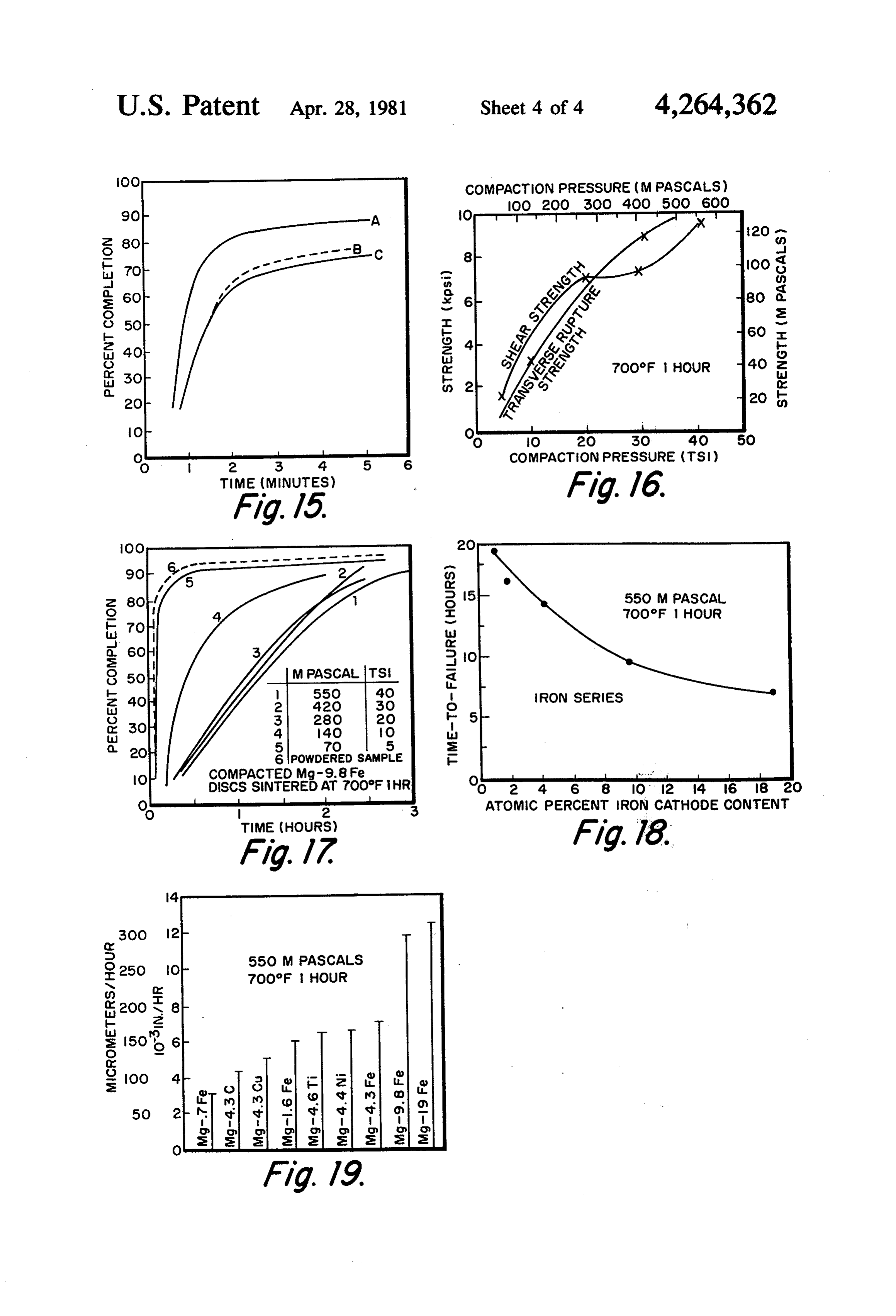
OO COMPACTION PRESSURE (MPASCALS)
too 5
2 3 4. 5 6 COMPACTION PRESSURE (TSI)
TIME (MINUTES)
7OOOF HOUR
M. PASCAL TS
RON SERIES
SPOWDERED SAMPLE
COMPACTED Mg-9.8 Fe
DISCS SINTEREDAT 7OO°F HR o, it is a
2 3 ATOMIC PERCENT IRON CATHODE CONTENT
TIME (HOURS)
7OOF HOUR
is too 4
Page 6
However, the short circuit resistance is not minimized.
SUPERCORRODNG GALVANC CELL, ALLOYS Electrical resistance between individual particles is a FOR GENERATION OF HEAT AND GAS function both of physical proximity and of the oxides that exist on the bond surface between the metal parti
This is a continuation-in-part of U.S. Patent Applica 5 cles (this is also true for the battery-like configuration). tion Ser. No. 855,035 filed Nov. 25, 1977, now aban Because high resistance surface oxides are present, ex doned. cellent mechanical contact may not assure intimate BACKGROUND OF THE INVENTION electrical contact. Due to the random method of joining the particles and low energy level of the balls used in
This invention generally relates to alloys which oper 10 the milling process in the aforesaid patent, some metal ate as short-circuited galvanic cells to corrode rapidly particles may not be paired into micro-cells but may in electrolyre such as seawater. Such an alloy is suitable remain free and will not react at all. Also, in this prior as a heat source; as a gas generator; or as a corroding art powder form, the internal cell resistance may be release link. minimized but the external or load resistance may be Sources of heat and hydrogen gas of various types are 15 high. Due to the high oxide level on the bond surface, well known in the art, especially by virtue of earlier compacting and sintering the powders fabricated by already issued United States Patents commonly as using the prior signed herewith such as: U.S. Pat. No. 3,884,216 issued etc., which has art teachings will not result in barstock, any significant mechanical strength.
May 20, 1975 for ELECTROCHEMICAL ENERGY
SOURCE FOR DIVER SUIT HEATING U.S. Pat. 20 to Aprovide strong mechanical and electrical bond is necessary a rapidly corroding galvanic cell alloy.
STRUCTURE FOR PRODUCTION OF HEAT AND SUMMARY HYDROGEN GAS U.S. Pat. No. 3,993,577 issued Nov. The supercorroding galvanic cell alloy (of this inven 23, 1976 for METHOD FOR PRODUCTION OF
HEAT AND HYDROGEN GAS and, U.S. Pat. No. 25 or more tion) is formed from a noble metal and an active metal, 4,017,414 issued Apr. 12, 1977 for POWERED METAL can than two constituents can be used. The metals SOURCE FOR PRODUCTION OF HEAT AND HY be the same as used in the battery-like or powder DROGEN GAS. configurations, or other metals may be used. In any At least two methods have been employed in the past case, the constituents are chosen based on their ability to form an alloy which will corrode at a predictable rate to achieve high corrosion rates. One is to construct a 30 in the available electrolyte. In particular, an alloys that short-circuited battery-like cell of noble and active metal plates separated by an electrode gap such as dis will react in seawater like a galvanic cell can be made closed in aforementioned U.S. Pat. No. 3,884,216. An using magnesium and a noble metal such as iron or other method is to form a powder by mechanically nickel. Any of the usual methods can be employed in joining the discrete particles of noble and active pow 35 producing the alloy; conventional dissolution, mechani ders such as disclosed in aforementioned U.S. Pat. Nos. cal alloying, etc. The proportions, particle size, and the 3,942,511, 3,993,577 and 4,017,414 where each powder homogeneity are selected to control the reaction rate. A particle is a small galvanic cell. maximum reaction rate can be achieved at some particu The battery-like cell has two principal disadvantages: lar mixture proportions. The resulting alloy is used in the power output is dependent upon the electrode gap either plate, bar or powder form. The plate and powder (internal cell resistance) and the resistance in the electri forms are especially suited for use as a heat source or a cal short circuits (external load) limits the reaction rate. gas generator. A corroding release link can be fabri In order to maximize power output, the electrode gap cated from sintered barstock. The supercorroding al must approach zero. Yet, to sustain the reaction, reac loys are superior to previous similar methods for pro tion products must be flushed away from the reacting 45 ducing heat and gas.
surfaces. This requires a small initial gap between the Usually alloys are formed to resist corrosion. How plates. The gap creates high internal cell resistance ever, the alloy of this invention is specifically intended which reduces the power obtainable from the cell. A to operate like a short-circuited galvanic cell for use as further decline in power occurs because of the gap a rapidly corroding alloy. By alloying the desired metal increase as the active plate is consumed. 50 constituents, the two main disadvantages of previous The resistance in the electrical short circuit between methods of producing high corrosion rates are elimi the noble and active materials can limit power output. nated. The alloy can have properties different from To maximize output, the external short circuit resis either of the constituents. Since the alloy is a uniform tance must be minimized. In the battery like configura mixture of the metals in intimate contact with each tion the resistance is kept low by providing several 55 other, there is no electrode gap to maintain so internal relatively short-length paths between the plates. Low cell resistance is minimized and the electrical short resistance spacers are used to maintain the electrode circuit resistance will be substantially a function only of gap. Thus, the electrical resistance is minimized within the path length between the centers of the reacting the configuration and material limits. aSS6S.
In the powdered form where each grain of powder is 60 Since no electrode gap exists, the power output of a a small galvanic cell similar to the larger battery-like heat source constructed of the alloy in plate form in the cell, noble metal particles are mechanically joined to short-circuited battery configuration will not decline as the surface of an active metal particle, as disclosed in the space between the plates increases due to material aforementioned U.S. Pat. No. 4,017,414. The combina consumption. A fluid circulation space will still have to tion retains the property and identity of each constitu 65 exist, however, to flush away reaction products. Elec ent. But each cell will react with itself, so no electrode trical resistance is the minimum attainable due to the gap is necessary or exists. The short circuit path length extremely short current lengths and because of the inti is minimized because the particles are in direct contact. mate contact and strong mechanical bond, i.e., the al
Page 7
loying, as disclosed herein, minimizes external resis FIG. 21 shows a sintered rapidly corroding disc. tance, FIG. 22 shows a sintered rapidly corroding link. In the powdered form of the alloy all of the metal DESCRIPTION OF PREFERRED EMBODIMENT particles are coupled into micro-cells because of the completely uniform mixture of the alloy constituents. A family of short-circuited galvanic cells formed Again, the electrical contact is the optimum attainable. from supercorroding magnesium alloys that react spon This supercorroding galvanic cell alloy has the addi taneously and vigorously with seawater to produce heat tional feature of being suitable for use as corroding and hydrogen gas have been developed. The galvanic barstock. In this form, corroding links can be made for cell alloys have been developed as a self-contained heat use either as primary or backup releases for oceano 10 source for Navy diver use, but they may also be used to graphic instruments. By adjusting the alloy composi generate hydrogen gas for buoyancy, thermodynamic tion, the reaction rates, and thus the release time, can be engines, and fuel cells. Because of their uniform and controlled. predictable behavior, the alloys can be used as corrod BRIEF DESCRIPTION OF THE DRAWINGS 15 ing links to retrieve oceanographic equipment.
Various cathodic materials in different proportions
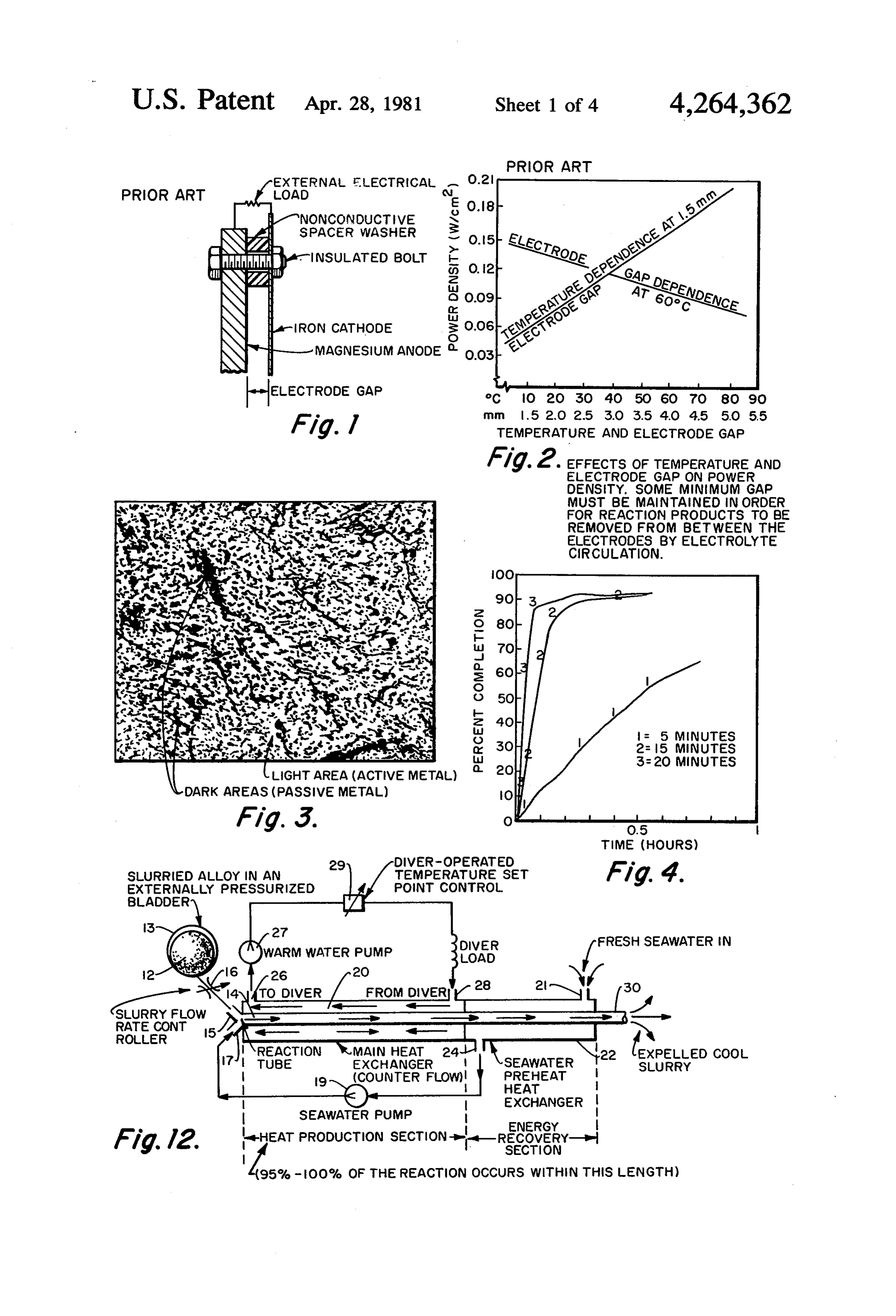
FIG. 1 shows a typical dual plate (prior art type) have been alloyed with magnesium. Tests were con battery cell. ducted to determine how the reaction is affected by FIG. 2 shows the effects of temperature and elec alloy compositions and constituent proportions, temper trode gap on power density, for a cell such as in FIG. 1. ature, and pressure.
FIG. 3 is an illustration of a micrograph showing an 20 enlarged cross sectional view of a small mechanically ingIntogeneral, the magnesium reacts with seawater accord formula:
alloyed magnesium particle of this invention having smaller particles of iron dispersed throughout the mag nesium matrix, for operation like a short-circuited gal vanic cell when in an electrolyte. 25 The reaction has a theoretical energy density of 14.929 FIG. 4 are curves showing the effect of high energy kJ/kg (1885 W-h/lb) and produces 0.921 liter of gas per milling time on reaction rate for magnesium based me gram of magnesium (14.8 ft/lb) at STP. By itself, mag chanical alloys of this invention. nesium corrodes slowly in seawater because of low, FIG. 5 shows the effect of prolonged milling on the local potential differences within the magnesium. When reaction rate AT for the mechanically alloyed magnesi 30 a suitable cathodic material is brought into close prox um-based alloys. imity and electrically connected with the magnesium, a -FIG. 6 are present completion time curves for a fam battery is formed, and the corrosion reaction proceeds ily of magnesium-iron mechanical alloys. rapidly. The dual plate cell shown in FIG. 1 represents FIG. 7 shows the effect of cathode material on reac tion rate for various mechanical alloys. 35.
this configuration. With the electrical load replaced by
FIG. 8 are percent completion curves for various and a short circuit, the reaction proceeds even more rapidly, magnesium-copper mechanical alloys. the cell efficiently produces heat and hydrogen gas. FIG. 9 shows power curves for magnesium-copper electrolyte The rate of reaction is known to be a function of (1) alloys. temperature, pH, salinity, and density, (2) FIG. 10 shows typical percent completion curves for The effects of plate anode cathode spacing, and (3) ambient pressure.
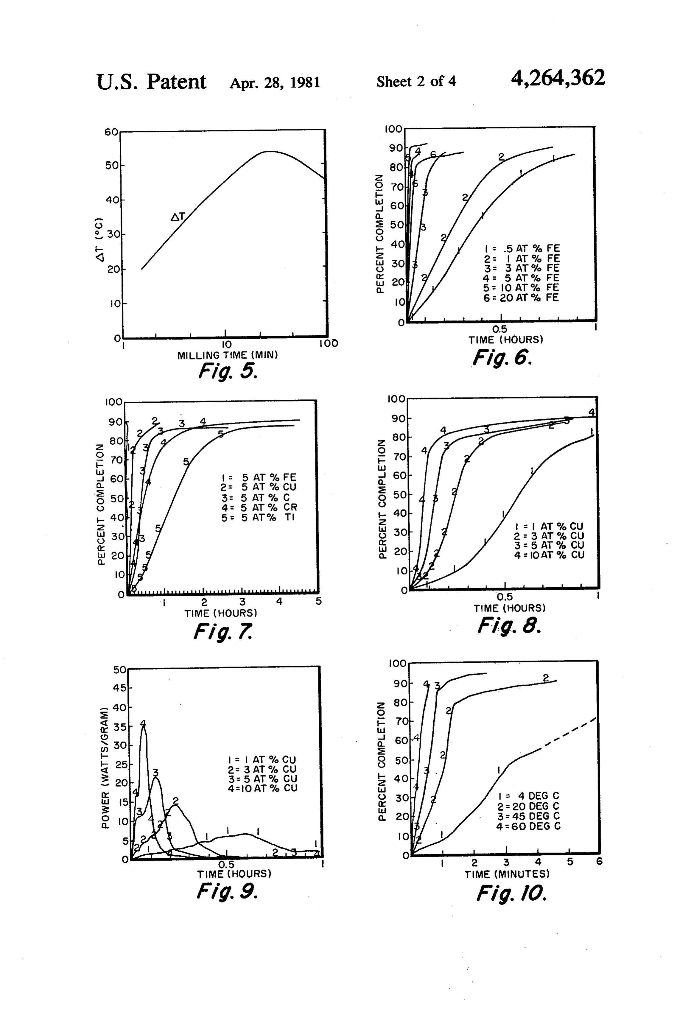
temperature and spacing on dual-plate a particular alloy as a function of temperature. cell performance are shown in FIG. 2. Some minimum FIG. 11 are typical power curves for the FIG. 10 gap must be maintained in order for reaction products alloy as a function of temperature.
FIG. 12 is a diagrammatic illustration of an arrange to be removed from between the electrodes by electro ment for a diver heater system utilizing supercorroding 45 lyte circulation.
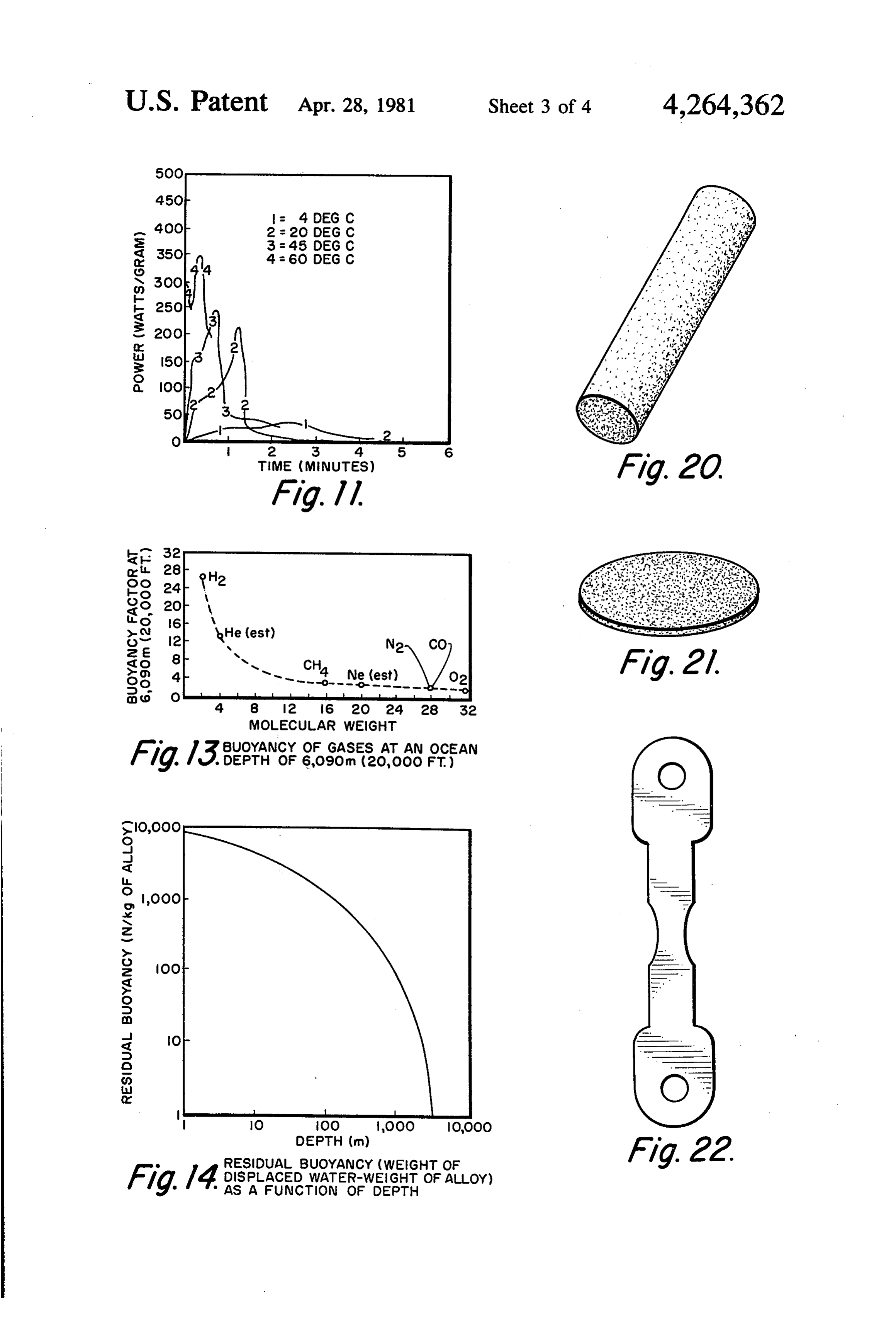
alloys of this invention as a heat source. A diver heater, based on the short-circuited dual FIG. 13 shows the buoyancy of gases at an ocean plate cell, was built and tested. The cell consisted of depth of 6,090 meters. alternate magnesium and iron plates spaced apart by FIG. 14 is a curve showing buoyancy factor as a copper washers that provided the short circuit. One of function of depth. 50 the main drawbacks to this construction is that as mag FIG. 15 shows that milling parameters affect reaction nesium is consumed, the electrode gap increases and characteristics. power output declines.
FIG. 16 shows the mechanical strength characteris To eliminate this decline and to achieve faster reac tics for Mg-9.8Fe alloy samples which were com tion rates, powdered metal mini-cells were conceived as pacted at different pressures and sintered at 700 F. for 55 discussed in aforementioned U.S. Pat. No. 4,017,414. one hour. The mini-cells were fabricated by ball-milling a mixture FIG. 17 shows the results of corrosion tests with discs of iron and magnesium powders (using lightweight made from the powdered alloy compacted at various ceramic balls). The milling produced composite parti pressures and then sintered where reaction rate is cles by mechanically bonding the constituents together. shown to decrease as compaction pressure increased. 60 Later tests showed that accelerated reaction rates FIG. 18 shows the time to failure for sintered alloy were achieved using the mini-cells, but that the reaction barstock, where the time-to-failure decreased (i.e., reac efficiency (percentage completion) in these prior art tion rate increased) with increasing cathode content for mini-cells was much lower than predicted. The opti the iron series alloys. mum rate occurred between 5 and 10 percent iron con FIG. 19 shows a summary of surface corrosion rates 65 tent. The accelerated reaction rate was attributed to the for various samples tested. close proximity of the anode-cathodic pairs and the FIG. 20 shows a sample of sintered cylindrical rap relatively large cathode surface area. The low effi idly corroding barstock. ciency was attributed to poor electrical contact due to
Page 8
oxides that exist on metal surfaces and low mechanical smaller passive metal particles shown as black. Many of strength of the Mg-Fe bond, as aforementioned. the passive metal particles are shown as elongated hav SUPERCORRODING ALLOY FORMATION ing been flattened in the milling process; the longest dimension of the active iron particles is about 30 mi
An alloying process called mechanical alloying has 5 crons. As is discussed below, the preferred powdered been used to overcome the problems that limited the alloy particle size is between 80 and 100 mesh. The prior mini-cells efficiency. Mechanical alloying gener intimate (atomic level) contact between the alloy con ally involves a high energy ball mill and does not use an stituents, low electrical resistance and high ratio of inert solvent with the powdered metal particles as dis exposed cathode to anode surface areas are the keys to closed in aforementioned U.S. Pat. No. 4,017,414. The 10 rapid corrosion rate.
active and passive metal particles are processed (i.e., Powder alloy performance was evaluated by record mechanically alloyed) dry. ing gas evolution as a function of time; this was used to Galvanic cell alloys have been fabricated into com determine reaction completion (energy output) and posite particles or mico-cells with as much as 20 percent reaction rate (power).
iron content using mechanical alloying techniques. 15 Percentage reaction completion at a particular time is Tests have shown that these magnesium-based galvanic calculated from the ratio of the volume of gas produced cell alloys react several orders of magnitude faster and at that time to the maximum theoretical gas production. more sufficiently than the previous mini-cells. Because Power is calculated essentially from the slope of the of their extremely high corrosion rate, these materials percent-completion-versus-time curve. Maximum gas were named supercorroding alloys. 20 production is calculated from the basic reaction equa Mechanical alloys can be produced, for example, in a tion using the actual amount of magnesium in a given high-energy ball mill by repeated flattening, fracturing, weight of alloy.
and wekding of the metal constituents (i.e., active and A series of experiments was conducted to select an passive metal particles). The energy of the impact of optimum milling time and particle size for further tests. colliding steel balls, with particles trapped between 25 Maximum reaction rate and reaction efficiency were them, creates atomically clean particle surfaces. When used as a basis of evaluation. Visual observation of the these clean surfaces come in contact during collisions, reaction revealed that particles that passed through a they cold-weld together. An inert atmosphere in the 100-mesh sieve would not stay submerged in the seawa mill prevents reoxidation of the clean surfaces. This also ter, but instead would float on the surface and form a avoids oxide coatings on the particle surfaces which 30 foam. This resulted in reduced reaction rates. It was reduce galvanic cell reaction. later observed that particles larger than 100 mesh would The tendency of powdered particles to cold-weld cycle from the bottom of the flask to the seawater sur together predominates during the early stage of the face and then sink. The cycling was caused by the for process. As milling continues, particles get harder and mation of a hydrogen bubble which buoyed the mini more brittle, and eventually a balance results between 35 cell particle. The hydrogen bubble was shed at the welding and particle fracturing. Continued milling re surface, and the particle sank. As a result, particles that fines the particles' characteristic layered structure. The would not pass through a 100-mesh sieve were used in thickness of each layer in the composite particle de subsequent tests. The estimated particle size is between creases from repeated impacts. 80 and 100 mesh.
During the early stages of the milling process the 40 Various tests and experiments were conducted and particles get larger. As milling continues particles get many of the results are shown in the curves of FIGS. harder, more brittie and break apart instead of deform 4-11 and 13-19.
ing; the particles structure becomes more refined and As previously discussed, continued milling refines the the iron particles get smaller. At some point in the mill layered structure and results in a reduction of exposed ing process, further milling results in a reduction of the 45 cathode surface area. To determine the effect of this corrosion rate. This is probably due to the cathode refinement on the reaction rate, magnesium-based alloys material becoming so finely dispersed throughout the of 5 atomic percent iron were milled for 5, 15 and 20 anode material that the ratio of cathode/anode particle minutes each and tested. The effect of the milling time surface area available for contact with the electrolyte on the reaction rate shows that the longer the powders decreases and hence the corrosion rate decreases. This 50 are milled, the more homogeneous they become, and point is substantially, less than saturation hardness for the more homogeneous powders react most rapidly. the material. It is important to note that to maximize Percent completion is shown in FIG. 4. The alloy corrosion rate and efficiency it is necessary to: (1) pro milled for 20 minutes reached the highest percent com vide a short electrolyte path length between anode and pletion in the least time. (The test of the alloy milled for cathode; (2) provide a high exposed rate of surface area 55 5 minutes were terminated prior to reaching comple between cathode and anode; (3) provide a strong tion, but, clearly, it reacts much more slowly.) (welded) bond between anode-cathode pairs; and (4) Additional alloys were fabricated and tested to deter provide a very low resistance (less than 10 ohms) mine the effect of further milling on reaction rate. The path for external currents to flow through the corrod time to maximum temperature rise of the water in an ing pairs. 60 open beaker was recorded. FIG. 5 shows, in a general The resulting mechanically alloyed powders are way, the effect of milling time on the reaction rate AT. small particles consisting of matrices of active metal An optimum milling time occurs when the time to reach having smaller particles of passive metals dispersed a maximum AT is the least. In this particular case alloys throughout. The micrograph of FIG. 3 shows a cross milled for 20 minutes showed the highest temperature section of a portion of an active metal particle (e.g., 65 rise in the east amount of time. Prolonged milling re magnesium) having many smaller passive metal parti sulted in a reduction of the reaction rate. The reduced cles (e.g., iron) dispersed within the active metal matrix. reaction rate is particularly attributed to a reduction in The active metal particle is shown as white and the the cathode to anode surface area exposed to the elec
Page 9
trolyte. It is expected that continued milling would A small number of other alloys have been produced result in further reduction in the reaction rate and that and evaluated. Some were magnesium based with a the reaction rate would be substantially reduced by the variety of cathodic materials; others were aluminum time that the alloy was milled to saturation hardness. and zinc based. A family of percent completion curves Based on these results, the remaining alloys were pre for magnesium based alloys with 5 atomic percent, Cu, pared under conditions similar to the 20-minute alloy. C, Cr, and Ti is shown in FIG. 7. (For a fixed cathode Other mill parameters such as speed of mill and ball proportion, reaction rate is dependent on cathode mate size (milling energy) and ball to powder ratio contribute rial.) An alloy of 5 atomic percent nickel was tested and to the reaction characteristics. For a particular combi found to react similarly to the 5 percent iron. Carbon is nation of anode and cathode materials and for a particu 10 also used the same as a passive cathodic metai in the lar batch size these parameters can be optimized as alloy, as shown in Table I and FIG. 7, since carbon acts shown in FIG. 15. Samples A. B and C of magnesium like a passive metal in galvanic cells. The mechanical with 9.8 iron (Mg-9.8 Fe) alloy were prepared using alloy composition can be varied to adjust the corrosion different milling parameters. In FIG. 15 the parameters rate.
used for milling sample A were optimum for a magne 15 The results of tests clearly show that iron and nickel sium anode material with 9.8 atomic percent iron. are the most reactive of the cathode materials tested. Magnesium alloys with different percentages of iron Table I shows that 5 percent carbon has a slightly were prepared and tested; the results are plotted in FIG. higher energy density than iron, but its power output is 6. (Up to 10 percent iron, reaction rate increases with much lower.
increasing iron content. Up to about 10 percent iron, the 20 To verify the dependence of the reaction process on reaction is evidently limited by the amount of cathode cathode content (shown by the magnesium-iron alloys) present. Beyond 10 percent, the iron begins to mask a series of tests on magnesium-copper alloys was con active areas of the magnesium, reducing the reaction ducted. The results of the copper family tests are shown rate.) They show that the reaction rate depends in FIGS. 8 and 9. (The time to reach a given percent strongly upon cathode material content up to approxi 25 completion varies approximately inversely with the mately 10 atomic percent. Several tests of the alloy with amount of copper in the alloy. The effect of copper 20 percent iron showed a significant decrease in the content is dramatically illustrated as doubled copper reaction rate. This phenomenon is believed to be caused content results in approximately doubled peak power by the reduction of exposed anode surface area due to outputs, i.e., reaction rates.) FIG. 8 shows that the time the increased cathode content. 30 to reach 50 percent completion is reduced by about half Cathodic percent does not appear to strongly affect as the amount of copper is doubled. This geometric the level of reaction completion. Thus, a particular relationship is dramatically illustrated by the power alloy can be selected on the basis of reaction rate or on curves of FIG. 9; peak power is approximately doubled the basis of energy density. A summary of energy den as copper content is doubled.
sity and other characteristics of alloys tested is shown in 35 Other alloys based on zinc and aluminum in place of Table I. The table shows that energy density (kJ/kg of magnesium have been fabricated and tested. The cath alloy) decreases with increasing cathode content, while ode materials were iron and copper. In seawater, none peak power increases. of these alloys showed a reactivity as great as the unal TABLE I. loyed base magnesium powder, so they have not been 40 pursued further.
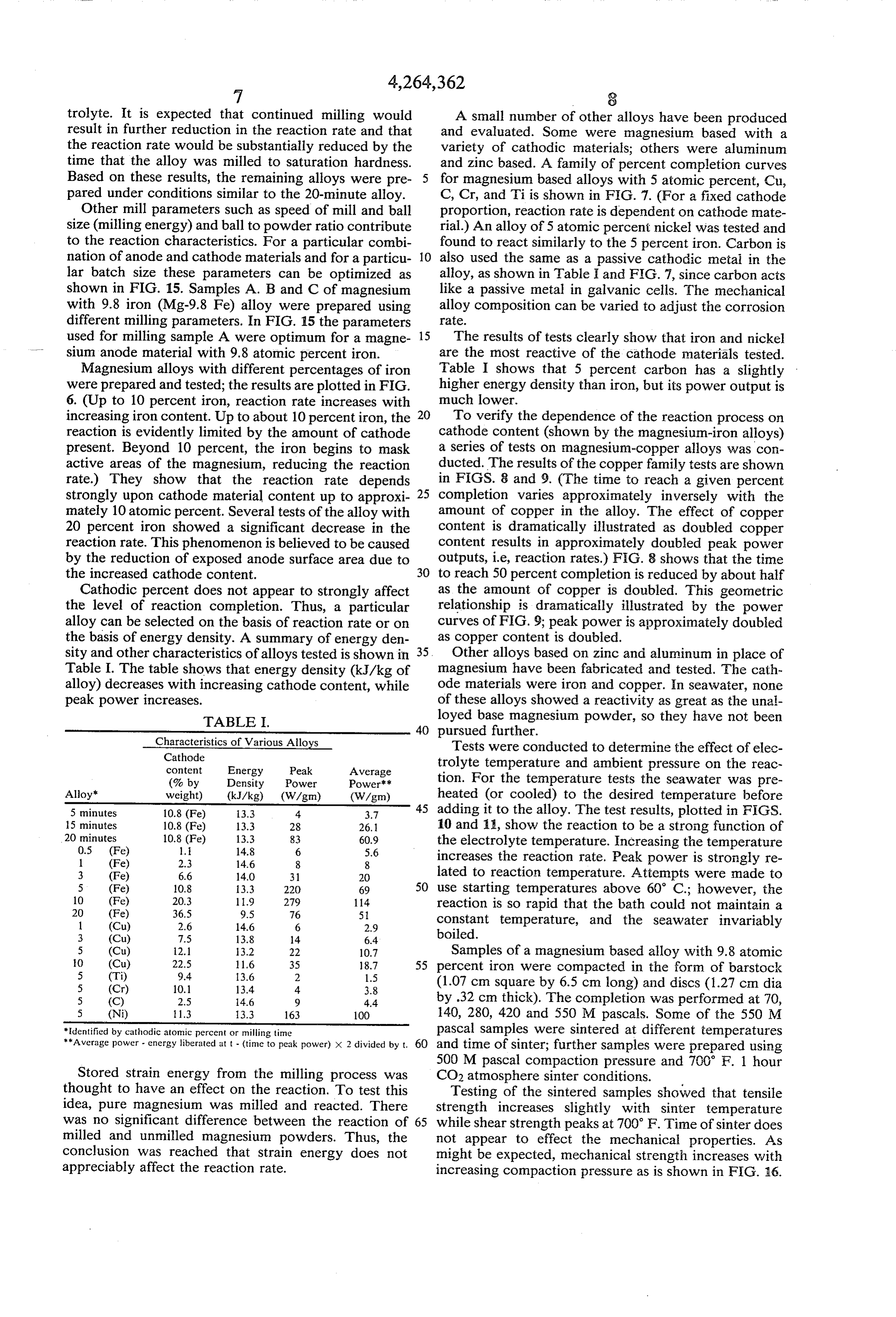
- Characteristics of Various Alloys Tests were conducted to determine the effect of elec Cathode content Energy Peak Average trolyte temperature and ambient pressure on the reac (% by Density Power Power tion. For the temperature tests the seawater was pre Alloy" weight) (kJ/kg) (W/gm) (W/gm) heated (or cooled) to the desired temperature before 5 minutes 10.8 (Fe) 13.3 4 3.7 45 adding it to the alloy. The test results, plotted in FIGS. 15 minutes 10.8 (Fe) 13.3 28 26. 10 and 11, show the reaction to be a strong function of 20 minutes
the electrolyte temperature. Increasing the temperature 1 (Fe) 2.3 14.6 8 8 increases the reaction rate. Peak power is strongly re 3 (Fe) 6.6 14.0 31 20 lated to reaction temperature. Attempts were made to 5 (Fe) 10.8 3.3 220 69 50 use starting temperatures above 60' C.; however, the 10 (Fe) 20.3 1.9 279 114 reaction is so rapid that the bath could not maintain a 20 (Fe) 36.5 9.5 76 5 1 (Cu) 2.6 14.6 6 2.9 constant temperature, and the seawater invariably 3. (Cu) 7.5 13.8 14 6.4 boiled.
5 (Cu) 12.1 3.2 22 10.7 Samples of a magnesium based alloy with 9.8 atomic 0 (Cu) 22.5 11.6 35 18.7 55 percent iron were compacted in the form of barstock 5 (Ti) 9.4 13.6 2 1.5 5 (Cr) 10.1 13.4 4. 3.8 (1.07 cm square by 6.5 cm long) and discs (1.27 cm dia 5 (C) 2.5 14.6 9 4.4 by .32 cm thick). The completion was performed at 70, 5 (Ni) 1.3 13.3 163 100 140, 280, 420 and 550 M pascals. Some of the 550 M *identified by cathodic atomic percent or milling time pascal samples were sintered at different temperatures **Average power - energy liberated at t - (time to peak power) x 2 divided by t. 60 and time of sinter; further samples were prepared using 500M pascal compaction pressure and 700' F. 1 hour
Stored strain energy from the milling process was CO2 atmosphere sinter conditions.
thought to have an effect on the reaction. To test this Testing of the sintered samples showed that tensile idea, pure magnesium was milled and reacted. There strength increases slightly with sinter temperature was no significant difference between the reaction of 65 while shear strength peaks at 700 F. Time of sinter does milled and unmilled magnesium powders. Thus, the not appear to effect the mechanical properties. As conclusion was reached that strain energy does not might be expected, mechanical strength increases with appreciably affect the reaction rate. increasing compaction pressure as is shown in FIG. 16.
Page 10
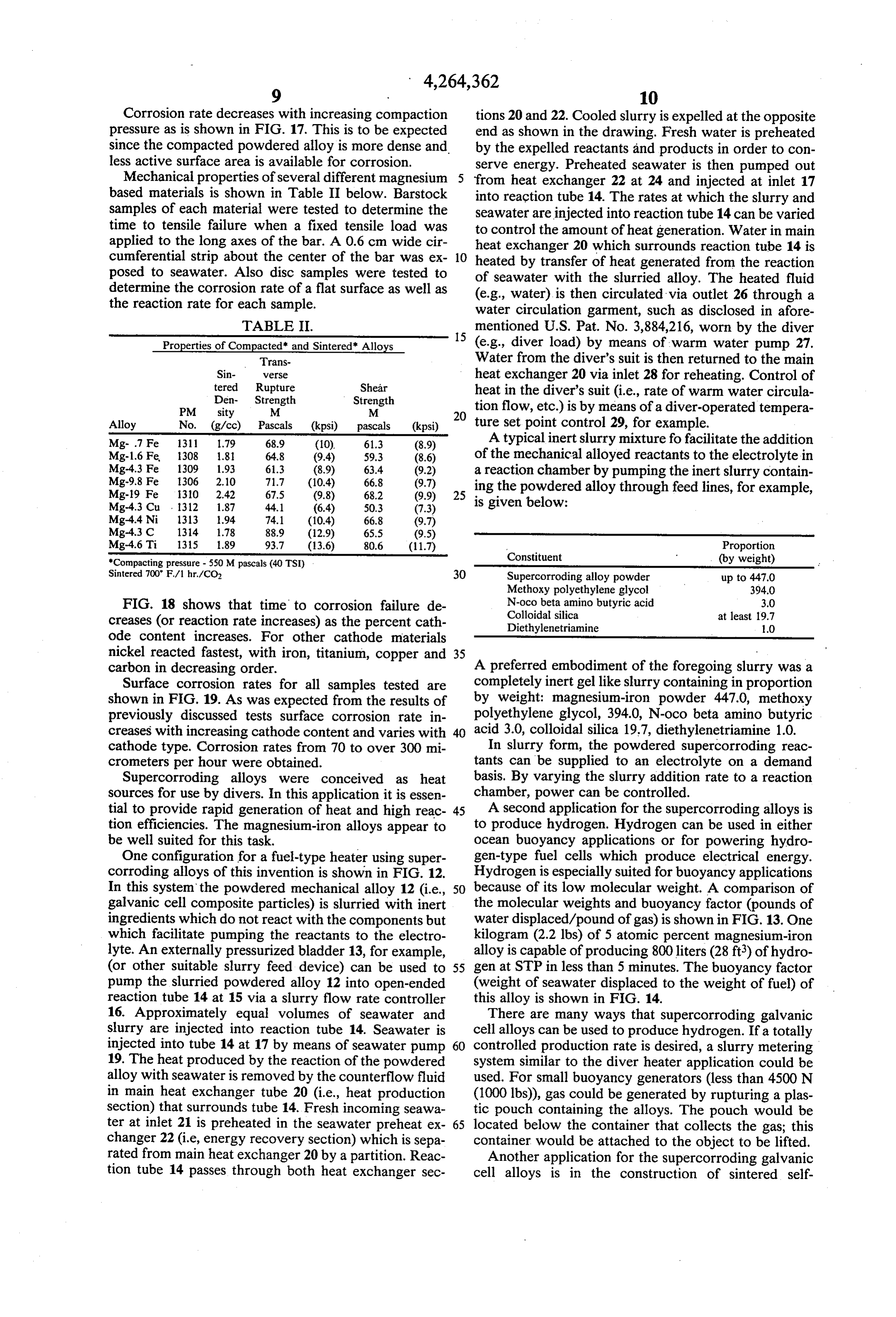
Corrosion rate decreases with increasing compaction tions 20 and 22. Cooled slurry is expelled at the opposite pressure as is shown in FIG. 17. This is to be expected end as shown in the drawing. Fresh water is preheated since the compacted powdered alloy is more dense and by the expelled reactants and products in order to con less active surface area is available for corrosion. serve energy. Preheated seawater is then pumped out Mechanical properties of several different magnesium 5 from heat exchanger 22 at 24 and injected at inlet 17 based materials is shown in Table II below. Barstock into reaction tube 14. The rates at which the slurry and samples of each material were tested to determine the seawater are injected into reaction tube 14 can be varied time to tensile failure when a fixed tensile load was to control the amount of heat generation. Water in main applied to the long axes of the bar. A 0.6 cm wide cir heat exchanger 20 which surrounds reaction tube 14 is cumferential strip about the center of the bar was ex 10 heated by transfer of heat generated from the reaction posed to seawater. Also disc samples were tested to of seawater with the slurried alloy. The heated fluid determine the corrosion rate of a flat surface as well as (e.g., water) is then circulated via outlet 26 through a the reaction rate for each sample. water circulation garment, such as disclosed in afore
TABLE II.
mentioned U.S. Pat. No. 3,884,216, worn by the diver
Properties of Compacted" and Sintered Alloys (e.g., diver load) by means of warm water pump 27. Trans Water from the diver's suit is then returned to the main Sin- verse heat exchanger 20 via inlet 28 for reheating. Control of tered Rupture Shear heat in the diver's suit (i.e., rate of warm water circula
PM sity M M 20 tion flow, etc.) is by means of a diver-operated tempera
Alloy No. (g/cc) Pascals (kpsi) pascals (kpsi) ture set point control 29, for example. Mg-.7 Fe 1311 1.79 68.9 (10). 61.3 (8.9) A typical inert slurry mixture fo facilitate the addition Mg-1.6 Fe 1308 1.81 64.8 (9.4) 59.3 (8.6) of the mechanical alloyed reactants to the electrolyte in
a reaction chamber by pumping the inert slurry contain
Mg-19 Fe 1310 2.42 67.5 (9.8) 68.2 (9.9) 25 ing the powdered alloy through feed lines, for example,
Mg-4.3 Cu 1312 1.87 44.1 (6.4) 50.3 (7.3) is given below: Mg-4.4 Ni 1313 1.94 74.1 (10.4) 66.8 (9.7)
Mg-4.3 C 1314 1.78 88.9 (12.9) 65.5 (9.5)
Mg-4.6 Ti 1315 1.89 93.7 (13.6) 80.6 (11.7) Proportion "Compacting pressure - 550 Mpascals (40 TSI) Constituent (by weight) Sintered 700 F/1 hr/CO 30 Supercorroding alloy powder up to 447.0 Methoxy polyethylene glycol 394.0
FIG. 18 shows that time to corrosion failure de N-oco beta aminobutyric acid 3.0
creases (or reaction rate increases) as the percent cath Diethylenetriamine 1.0 ode content increases. For other cathode materials nickel reacted fastest, with iron, titanium, copper and 35 carbon in decreasing order. A preferred embodiment of the foregoing slurry was a Surface corrosion rates for all samples tested are completely inert gel like slurry containing in proportion shown in FIG. 19. As was expected from the results of by weight: magnesium-iron powder 447.0, methoxy previously discussed tests surface corrosion rate in polyethylene glycol, 394.0, N-oco beta amino butyric creases with increasing cathode content and varies with 40 acid 3.0, colloidal silica 19.7, diethylenetriamine 1.0. cathode type. Corrosion rates from 70 to over 300 mi In slurry form, the powdered supercorroding reac crometers per hour were obtained. tants can be supplied to an electrolyte on a demand Supercorroding alloys were conceived as heat basis. By varying the slurry addition rate to a reaction sources for use by divers. In this application it is essen chamber, power can be controlled. tial to provide rapid generation of heat and high reac 45 A second application for the supercorroding alloys is tion efficiencies. The magnesium-iron alloys appear to to produce hydrogen. Hydrogen can be used in either be well suited for this task. ocean buoyancy applications or for powering hydro One configuration for a fuel-type heater using super gen-type fuel cells which produce electrical energy. corroding alloys of this invention is shown in FIG. 12. Hydrogen is especially suited for buoyancy applications In this system the powdered mechanical alloy 12 (i.e., 50 because of its low molecular weight. A comparison of galvanic cell composite particles) is slurried with inert the molecular weights and buoyancy factor (pounds of ingredients which do not react with the components but water displaced/pound of gas) is shown in FIG. 13. One which facilitate pumping the reactants to the electro kilogram (2.2 lbs) of 5 atomic percent magnesium-iron lyte. An externally pressurized bladder 13, for example, alloy is capable of producing 800 liters (28 ft) of hydro (or other suitable slurry feed device) can be used to 55 gen at STP in less than 5 minutes. The buoyancy factor pump the slurried powdered alloy 12 into open-ended (weight of seawater displaced to the weight of fuel) of reaction tube 14 at 15 via a slurry flow rate controller this alloy is shown in FIG. 14.
16. Approximately equal volumes of seawater and There are many ways that supercorroding galvanic slurry are injected into reaction tube 14. Seawater is cell alloys can be used to produce hydrogen. If a totally injected into tube 14 at 17 by means of seawater pump 60 controlled production rate is desired, a slurry metering 19. The heat produced by the reaction of the powdered system similar to the diver heater application could be alloy with seawater is removed by the counterflow fluid used. For small buoyancy generators (less than 4500 N in main heat exchanger tube 20 (i.e., heat production (1000 lbs)), gas could be generated by rupturing a plas section) that surrounds tube 14. Fresh incoming seawa tic pouch containing the alloys. The pouch would be ter at inlet 21 is preheated in the seawater preheat ex 65 located below the container that collects the gas; this changer 22 (i.e., energy recovery section) which is sepa container would be attached to the object to be lifted. rated from main heat exchanger 20 by a partition. Reac Another application for the supercorroding galvanic tion tube 14 passes through both heat exchanger sec cell alloys is in the construction of sintered self
Page 11
destructing corroding links, dics, etc., as discussed the scope of the appended claims the invention may be above. For example, the alloy powders can be sintered practiced otherwise than as specifically described. to form barstock, such as shown in FIG. 20, suitable for We claim:
making self-contained corroding links, or can be sin 1. Supercorroding galvanic cell alloys for generating tered to form corroding discs such as shown in FIG. 21. 5 heat and hydrogen gas upon activation in an electrolyte, In many ocean engineering applications a timed release comprising:
device is needed to shed temporary hydro-dynamic a. uniform mechanical alloy produced by the re drag reduction shrouds or to aid in recovering instru peated flattening, fracturing and cold welding to mentation. The link can be in the form of a round pin gether of active anodic powered metal and passive which holds the object to be released to an anchor or O cathodic powdered material constituents in an inert instrument package. A variety of devices are presently atmosphere to form minute mechanically alloyed used. Most of the devices are either not totally reliable composite galvanic cell particles of completely or are extremely expensive. Prior art type corroding homogeneous mixture;
links require two separate parts (anode and cathode) . . said anodic and cathodic powdered particles being that must be electrically connected to promote the link 15 substantially atomically clean and absent of oxides destruction. The electrical connections to the parts are on their surfaces and being coupled into micro-cells often unreliable and break down. Since the supercor having strong mechanical bonds and intimate roding galvanic cell alloys are inherently self-destruct atomic-level electrical contact; said micro-cells ing, the need for electrical connections is removed. having extremely short current path lengths be Release times can be controlled either by sizing the tween the alloyed constituents; dimensions of the supercorroding alloy or by selecting c. said anodic powdered metal and passive cathodic the alloy composition. Either way, a variety of corrod powdered material being mechanically alloyed to a ing links, such as shown in FIG.22 for example, that last point substantially less than saturation hardness for for periods of minutes to hours can readily be manufac providing desired homogeneity and optimum reac tured using the present supercorroding galvanic cell 25 tion time in said electrolyte; alloys. In the disc form, as in FIG. 21, for example, one d. each of said uniform mechanically alloyed galvanic surface is exposed to the ambient seawater. When cell particles consisting of an active anodic metal mounted on a device, upon immersion the surface will matrix having numerous smaller particles of pas corrode and the disc will eventually fail. The failure can sive cathodic material trapped and dispersed be used to facilitate flooding and scuttling or to activate 30 throughout said active anodic metal matrix in a other mechanical and electrical functions. If desired, barstock, such as in FIG. 20, for example, or pre-formed characteristic homogeneous layered structure; links such as in FIG. 22 can be coated with an epoxy e. said active anodic metal being powdered magne except for a circumferential area about the center to sium;
preclude seawater contact from all but the exposed 35. f, lected said passive cathodic powder material being se from any of iron, copper, titanium, chro center area.
Desirable failure time for corrodable linkage devices mium, carbon, and nickel, including combinations varies depending on the application. For example, it thereof;
may be desired to retrieve a sampling device within one g. said mechanically alloyed galvanic cell particles to eight hours of deployment. In another application, it 40 being operable to corrode at a predictable and may be desirable to scuttle a surface float such as a rapid rate in a desired electrolyte for producing sonobuoy after eight to ten days of operation. heat and gas by proper selection of constituents and As a heat source, the alloys can be used to warm percentages thereof and the homogeneity of the divers or melt ice in arctic regions. The hydrogen pro alloy; said mechanically alloyed galvanic cell parti duced can be used to power fuel cells and internal com 45 cles having optimum electrical contact between bustion engines, or to provide buoyancy for lifting active and passive material and no electrode gap to heavy objects from the ocean floor. maintain resulting in minimal internal electrical Supercorroding alloys have advantages over the resistance and improved reaction rates in suitable prior art type fixed-plate cells and mini-cells in diver electrolyte; wherein maximum corrosion rate and heating applications. They are at least an order of mag 50 efficiency is provided with minimum electrolyte nitude more reactive than either the fixed-plate cell or bath length, high exposed surface area ratio, strong the mini-cells. They are independent of external electri welded bonds and less than 10 ohms resistance cal resistance and internal electrical resistance is mini for external currents to flow through between the mal. They are significantly more efficient than the pre corroding cathode and anode material pairs of the vious type powdered mini-cells and have a much 55 supercorroding galvanic cell alloyed particles. greater energy density than the fixed-plate cells. Reac 2. Supercorroding galvanic cell alloys as in claim 1 tion rates can be selected by choosing the composition wherein said active metal powder consists of from ap of the alloy. The output of hydrogen produced can be proximately 80 to 95 atomic percent powdered magne varied by controlling either the reaction temperature or sium particles.
the metering rate of the alloy to a reaction chamber. 60 3. Supercorroding galvanic cell alloys as in claim 1 By forming a wide variety of alloys, a range of reac wherein said passive material powder consists of from tion rates can be obtained. Alloys can be chosen for use approximately 0.5 to 20 atomic percent powdered iron by matching their reaction rates to the application: high particles. w rates are suitable for heat and gas generation; low, 4. Supercorroding galvanic cell alloys as in claim 1 steady, predictable rates are suited to corroding links. 65 wherein said passive material powder consists of from 1 Obviously many modifications and variations of the to 10 atomic percent powdered copper particles. present invention are possible in the light of the above 5. Supercorroding galvanic cell alloys as in claim 1 teachings. It is therefore to be understood that within wherein said passive material powder consists of up to
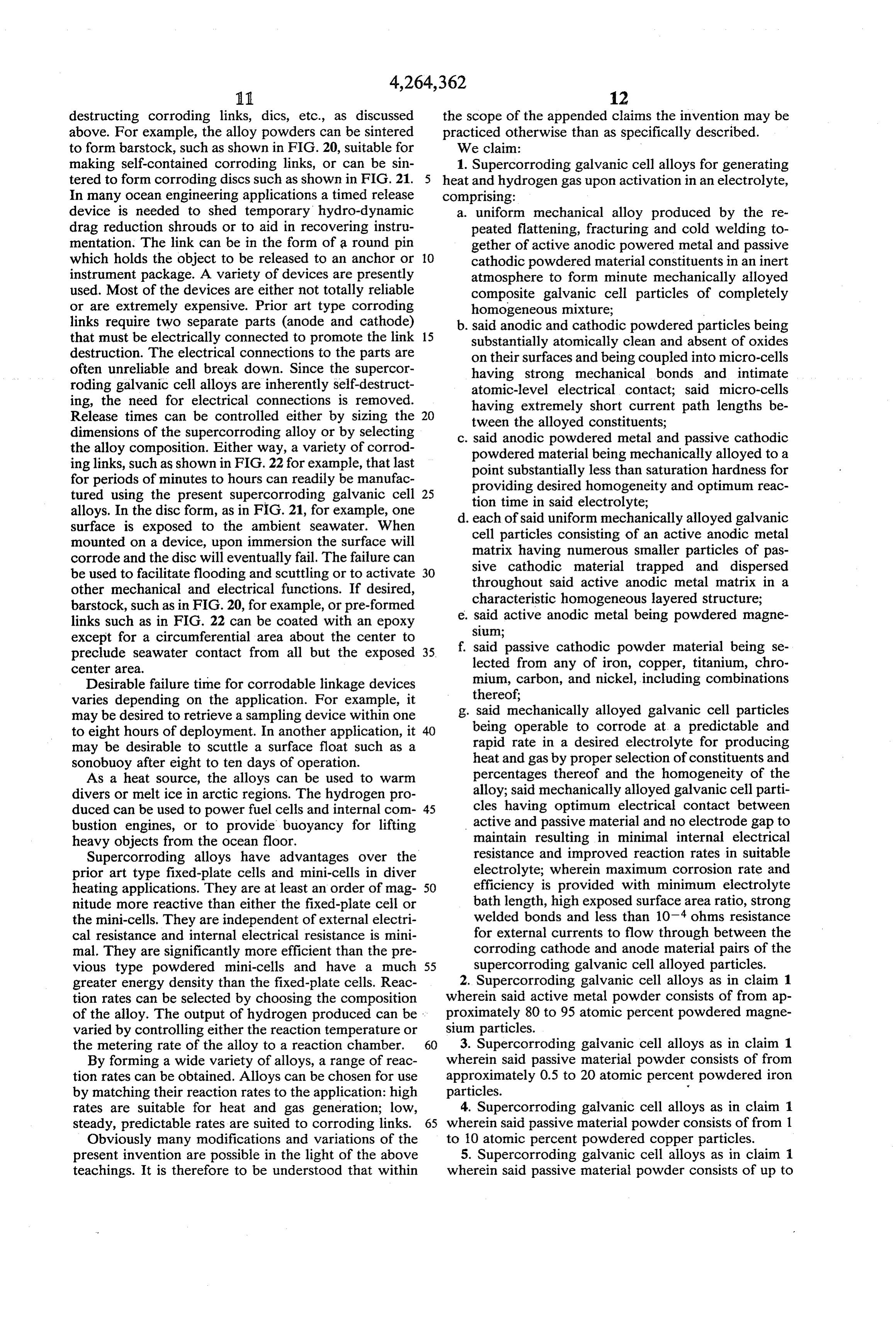
Page 12
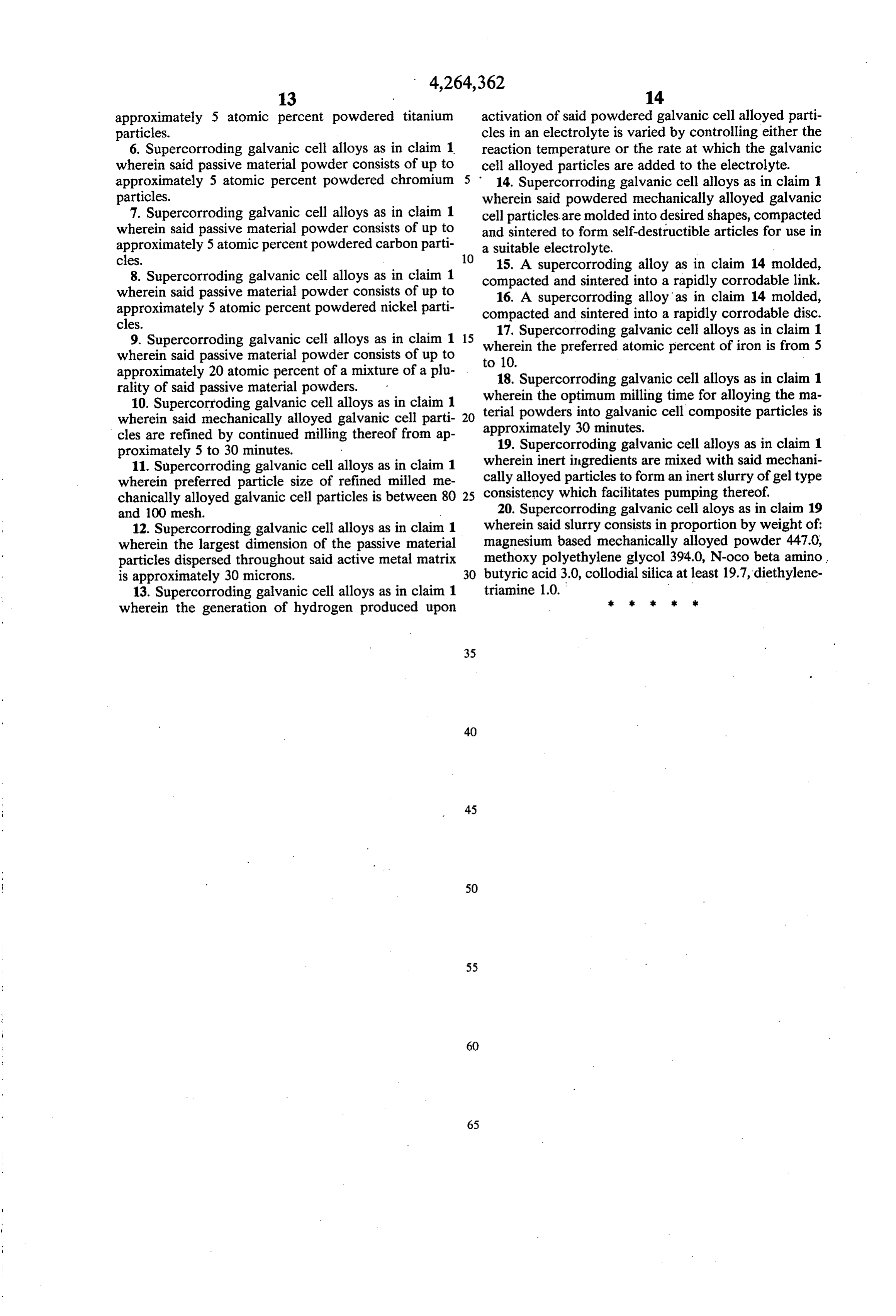
approximately 5 atomic percent powdered titanium activation of said powdered galvanic cell alloyed parti particles. cles in an electrolyte is varied by controlling either the 6. Supercorroding galvanic cell alloys as in claim 1 reaction temperature or the rate at which the galvanic wherein said passive material powder consists of up to cell alloyed particles are added to the electrolyte. approximately 5 atomic percent powdered chromium 5 : 14. Supercorroding galvanic cell alloys as in claim particles. wherein said powdered mechanically alloyed galvanic 7. Supercorroding galvanic cell alloys as in claim 1 cell particles are molded into desired shapes, compacted wherein said passive material powder consists of up to and sintered to form self-destructible articles for use in approximately 5 atomic percent powdered carbon parti a suitable electrolyte.
cles. 10 15. A supercorroding alloy as in claim 14 molded, 8. Supercorroding galvanic cell alloys as in claim 1 compacted and sintered into a rapidly corrodable link. wherein said passive material powder consists of up to 16. A supercorroding alloy as in claim 14 molded, approximately 5 atomic percent powdered nickel parti compacted and sintered into a rapidly corrodable disc. cles.
9. Supercorroding galvanic cell alloys as in claim 1 15 wherein the preferred galvanic 17. Supercorroding atomic cell alloys as in claim 1 percent of iron is from 5 wherein said passive material powder consists of up to to 10.
approximately 20 atomic percent of a mixture of a plu 18. Supercorroding galvanic cell alloys as in claim 1 rality of said passive material powders. wherein the optimum milling time for alloying the ma 10. Supercorroding galvanic cell alloys as in claim 1 terial powders into galvanic cell composite particles is wherein said mechanically alloyed galvanic cell parti 20 approximately 30 minutes.
cles are refined by continued milling thereof from ap 19. Supercorroding galvanic cell alloys as in claim 1 proximately 5 to 30 minutes. wherein inert ingredients are mixed with said mechani 11. Supercorroding galvanic cell alloys as in claim 1 wherein preferred particle size of refined milled me cally alloyed particles to form an inert slurry of gel type chanically alloyed galvanic cell particles is between 80 25 consistency which facilitates pumping thereof. and 100 mesh. 20. Supercorroding galvanic cell aloys as in claim 19 12. Supercorroding galvanic cell alloys as in claim 1 wherein said slurry consists in proportion by weight of: wherein the largest dimension of the passive material magnesium based mechanically alloyed powder 447.0, particles dispersed throughout said active metal matrix methoxy polyethylene glycol 394.0, N-oco beta amino is approximately 30 microns. 30 butyric acid 3.0, collodial silica at least 19.7, diethylene 13. Supercorroding galvanic cell alloys as in claim 1 triamine 1.0.
wherein the generation of hydrogen produced upon k e sk k k
Provenance
- Collection
- Cited prior art
- Original PDF
- patentimages.storage.googleapis.com →
- Filed
- 1979-08-13
- Pages
- 12
- Method
- pdftotext (the PDF's own text layer) + pdftoppm 300dpi page scans
- Source
- Google Patents bibliographic record
- Granted
- 1981-04-28
- Inventors
- Sergius S. Sergev; Stanley A. Black; James F. Jenkins; US Department of Navy
- Transcribed from
- patentimages.storage.googleapis.com →