patent · US4246466
Electric heat storage apparatus
20 January 1981
Page 1 — bibliographic record
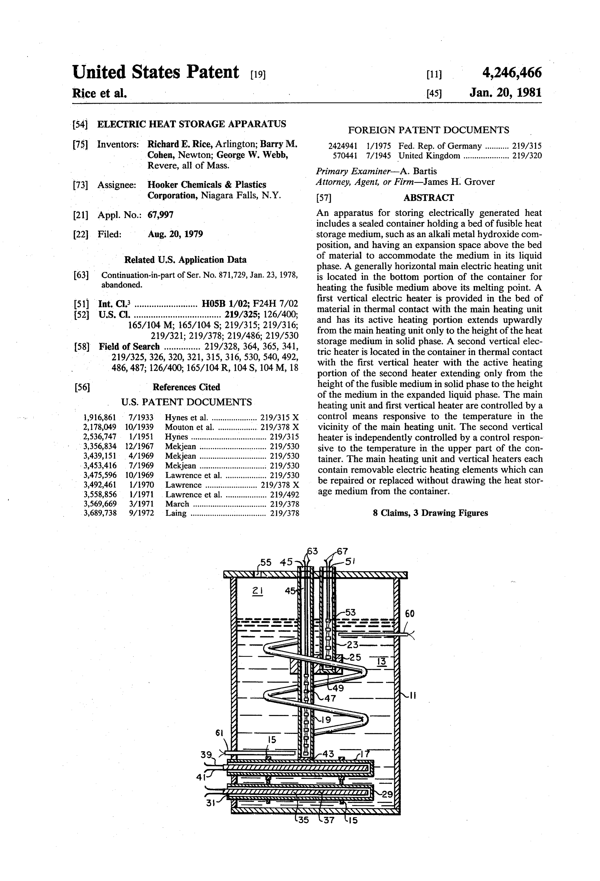
United States Patent (19) 11 4,246,466 Rice et al. 45 Jan. 20, 1981 54 ELECTRICHEAT STORAGE APPARATUS FOREIGN PATENT DOCUMENTS 75) Inventors: Richard E. Rice, Arlington; Barry M. 2424.941 1/1975 Fed. Rep. of Germany ........... 219/315 Cohen, Newton; George W. Webb, 570441 7/1945 United Kingdom..................... 219/320 Revere, all of Mass. Primary Examiner-A. Bartis 73) Assignee: Hooker Chemicals & Plastics Attorney, Agent, or Firm-James H. Grover Corporation, Niagara Falls, N.Y. (57 ABSTRACT 21 Appl. No.: 67,997 An apparatus for storing electrically generated heat includes a sealed container holding a bed of fusible heat 22 Filed: Aug. 20, 1979 storage medium, such as an alkali metal hydroxide com position, and having an expansion space above the bed
Related U.S. Application Data of material to accommodate the medium in its liquid phase. A generally horizontal main electric heating unit 63 Continuation-in-part of Ser. No. 871,729, Jan. 23, 1978, is located in the bottom portion of the container for abandoned. heating the fusible medium above its melting point. A (51) Int. Cl........................... H05B 1/02; F24H 7/02 first vertical electric heater is provided in the bed of 52 U.S. C. .................................... 219/325; 126/400; material in thermal contact with the main heating unit 165/104 M, 165/104 S; 219/315; 219/316; and has its active heating portion extends upwardly 219/321; 219/378; 219/486; 219/530 from the main heating unit only to the height of the heat 58) Field of Search ............... 219/328, 364, 365, 341, storage medium in solid phase. A second vertical elec tric heater is located in the container in thermal contact 219/325, 326, 320, 321, 315, 316, 530, 540, 492, with the first vertical heater with the active heating 486, 487; 126/400; 165/104 R, 104 S, 104M, 18 portion of the second heater extending only from the 56 References Cited height of the fusible medium in solid phase to the height
of the medium in the expanded liquid phase. The main heating unit and first vertical heater are controlled by a 1,916,861 7/1933 Hynes et al...................... 219/315X control means responsive to the temperature in the 2,178,049 10/1939 Mouton et al. .. ... 219/378 X vicinity of the main heating unit. The second vertical 2,536,747 1/1951 Hynes ................................... 219/315 heater is independently controlled by a control respon 3,356,834 12/1967 Mekjean ............................... 219/530 sive to the temperature in the upper part of the con 3,439,151 4/1969 Mekjean ............................... 219/530 tainer. The main heating unit and vertical heaters each 3,453,416 7/1969 Mekjean ............................... 219/530 contain removable electric heating elements which can 3,475,596 10/1969 Lawrence et al. ................... 219/530 be repaired or replaced without drawing the heat stor
3,558,856 1/1971 . Lawrence et al. ................... 219/492 age medium from the container. 3,569,669. 3/1971 March .................................. 219/378 3,689,738 9/1972 Laing ................................... 219/378 8 Claims, 3 Drawing Figures
Page 2
Drawing sheet — no readable text.
Page 3
Drawing sheet — no readable text.
Page 4
path, as the heat conductivity of the length of metal
ELECTRICHEAT STORAGE APPARATUS may not be sufficient to provide an escape path before high pressure is built up from the lower heater source.
This application is a continuation-in-part of our appli However, the vertical heater section, being activated cation Ser. No. 871,729 entitled IMPROVED APPA when the unit is discharged, has a substantial amount of RATUS FOR STORING HEAT filed Jan. 23, 1978, surface area exposed to the gas in the clearance space now abandoned. until the level of the melting heat storage medium rises BACKGROUND OF THE INVENTION to its highest level. Since heat dissipation from the heater surface to the liquid medium is much more effec
The present invention relates to an apparatus useful 10 tive than to a gaseous ambient, this can result in serious to store heat. The heat storage medium utilized in the overheating of the heating element exposed to the gas present apparatus is fusible, that is, it undergoes a solid and in premature failure of the element and rapid corro liquid phase change during its charging and discharging sion of the heater surfaces exposed to the gas. cycles. During such cycles, the density of the medium A preferred type of heater consists of an electrical decreases (i.e., the volume increases) as the medium 15 heating element, such as Nichrome wire, inside of a melts. To accommodate this volume change, a clear metallic tube which is immersed in the heat storage ance space is provided which normally contains gas medium. The tube protects the element from corrosion for example, air. The present invention provides an by the medium, and from electrical short-circuiting by improved means for alleviating high pressures which the medium, many of which are electrically conducting may be produced within the heat storage container 20 when in the molten state.
when the heat storage medium is converted from the In actual practice, the heaters are arranged within the solid state to the liquid state. The present invention also container, molten heat storage medium is introduced provides an improved arrangement of heating units into the container, allowed to solidify, and the unit whereby the heating elements may be replaced without transported to an installation site. The embedded heat draining the heat storage medium from the heat storage 25 ers are then utilized to melt, or charge, the heat storage container. medium and impart heat into the system. Main heating When uniform heat is applied to a solid material held units of the prior art have commonly been of the type in in a container, the uniform heat throughout the solid which the heating element, an electrical insulating ma results in the even liquefaction of the solid. The formed terial, and a metallic outer sheath, are constructed as an liquid can expand into the clearance space, and no ad 30 inseparable unit, and are immersed in the heat storage verse internal pressures are built up within the con medium. Such designs do not lend themselves to in situ tainer. However, it is impractical to apply a uniform repair or replacement of heating elements. Typical prior heat to all parts of a tank of solid heat storage material. art heater arrangements are found in U.S. Pat. Nos. In actual practice, localized heaters are utilized, and the 3,356,834; 3,439,151; 3,453,416; 3,475,596; 3,492,461; problem of internal pressures within the container is 35 and 3,558,856.
encountered and must be reckoned with. Preferred heat storage mediums are alkali metal hy In operation, when the localized heaters are utilized droxide compositions. Such compositions are preferred to melt a solid heat storage medium, which may occur because of their relatively high storage capacities, high either on initial start-up or during any cycle in which heats of fusion, broad operative ranges, relative inert the heat storage medium has been allowed to solidify, a ness, and their low vapor pressures. Alkali metal hy large amount of heat is supplied to the heat storage droxides have melting points ranging from about 272 medium at relatively localized points. Such localized C. for cesium to about 450° C. for lithium. The incorpo heating melts the solid material in pools contained ration of additives such as corrosion inhibitors and non within the otherwise solid material. As the solid melts, reducing agents into the alkali metal hydroxide heat the expansion of the liquid phase produces high internal 45 storage compositions facilitates the production of useful pressures which are capable of distorting or rupturing mixtures with a variety of melting points. the container. Sodium hydroxide compositions are commonly avail Presently, heat storage units are fabricated by posi able and are aptly suited for use as the heat storage tioning one or more main heating units within the heat medium of the present invention. Relatively pure so storage container. These units are usually located in the 50 dium hydroxide has a melting point of about 318 C. bottom portion of the container. A vertical heater may However, compositions including other salts may con be utilized to provide a pressure escape path to the sist of liquid-solid mixtures in the range from about 232 clearance space for the expanding liquid medium. The C. to about 340 C. During a heat storage cycle, sodium use of only vertical heaters is not feasible because the hydroxide may be heated to temperatures as high as heated liquid medium circulates very readily and rap 55 675 C. without harm. Normal operating temperatures idly rises to the top. Thus, the maximum temperature of heat storage units containing sodium hydroxide com allowable in the system would be reached at the top positions as a heat storage medium range from about while the temperature at the bottom would be consider 100 C. to about 500 C.
ably lower, and the full heat storage capacity of the The previously proposed heat storage devices present medium could not be utilized. The prior art proposes an 60 a problem when the immersed heating elements fail. In escape channel by providing a vertical heater which order to repair or replace the defective element, the may be a length of metal thermally connected to and heat storage medium must be melted and drained, the heated by one or more of the lower main heaters, or by element repaired and replaced, and the heat storage a vertical section of a main heater which extends to the medium returned to the container. Such maintenance clearance space. The length of metal or the vertical 65 and repair operations are very costly. As a practical section of heater extend through the level of the heat matter, the units requiring repair are usually taken out storage medium when liquid. The vertical heater sec of service and returned to the manufacturer, entailing tion is the more reliable means of providing an escape the substantial expense of disconnecting, shipping, and
Page 5
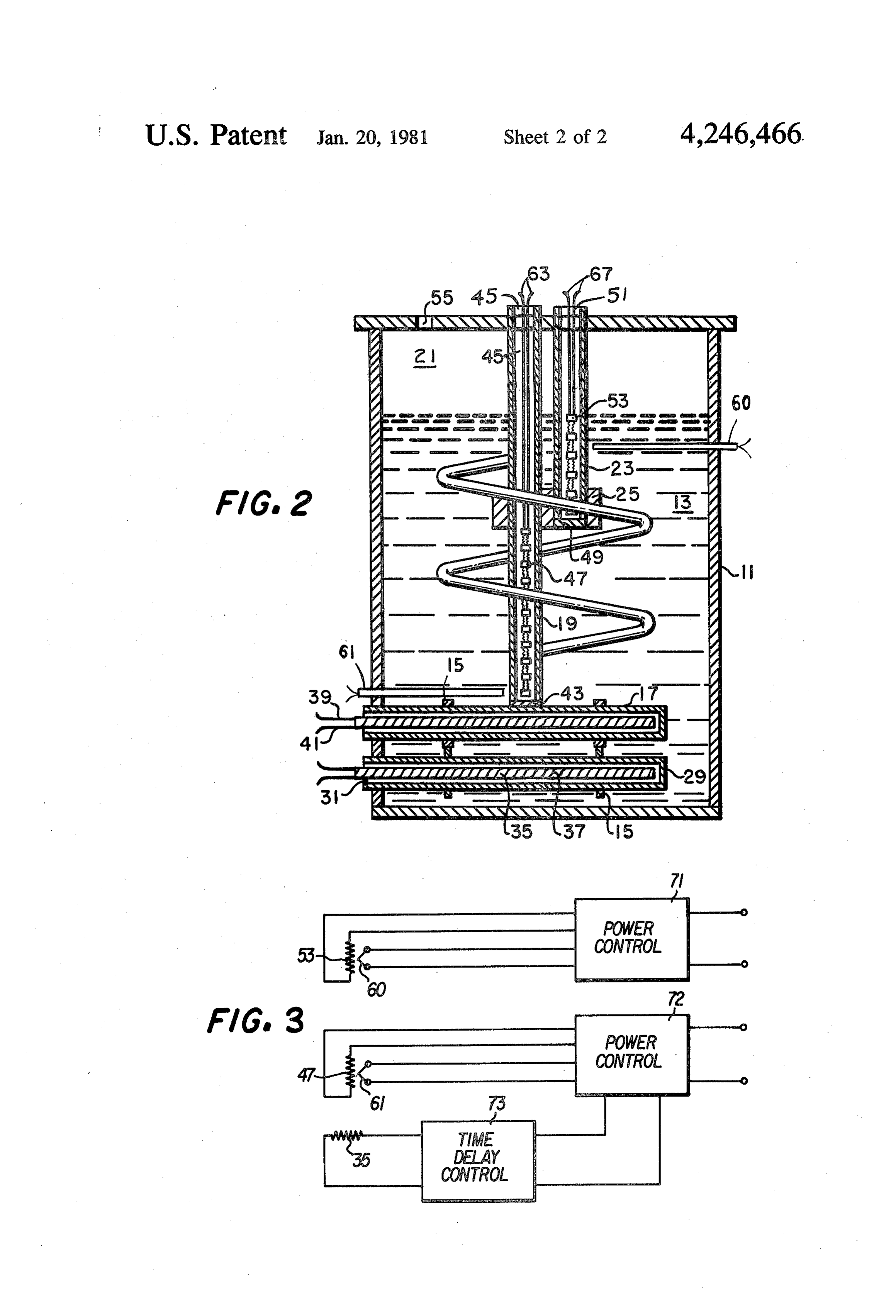
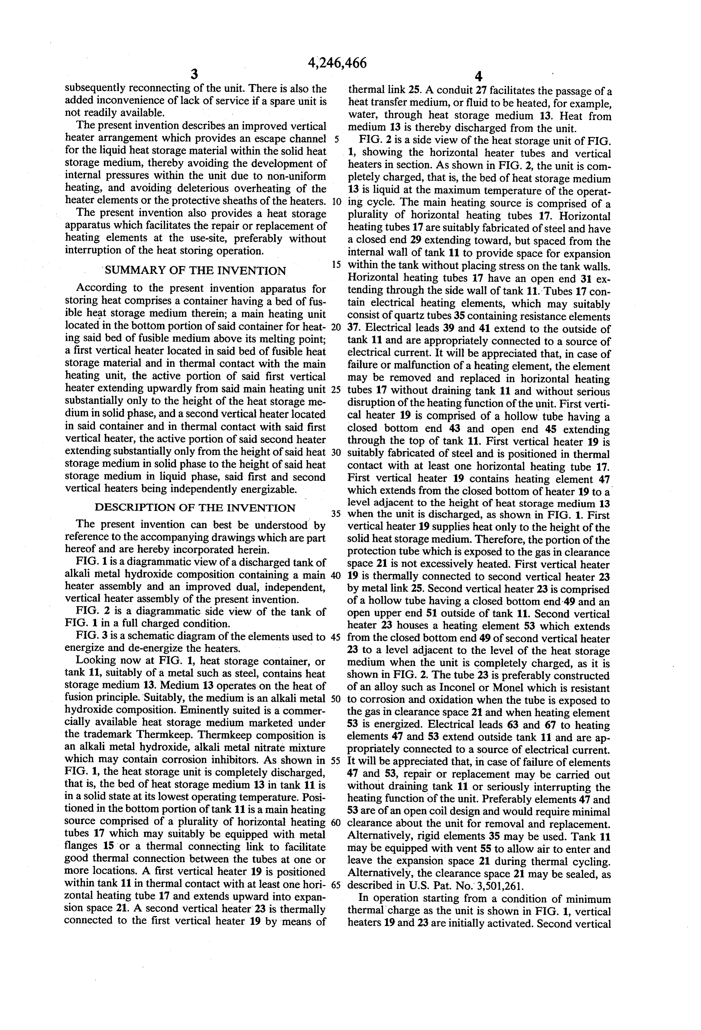
subsequently reconnecting of the unit. There is also the thermal link 25. A conduit 27 facilitates the passage of a added inconvenience of lack of service if a spare unit is heat transfer medium, or fluid to be heated, for example, not readily available. water, through heat storage medium 13. Heat from The present invention describes an improved vertical medium 13 is thereby discharged from the unit. heater arrangement which provides an escape channel 5 FIG. 2 is a side view of the heat storage unit of FIG. for the liquid heat storage material within the solid heat 1, showing the horizontal heater tubes and vertical storage medium, thereby avoiding the development of heaters in section. As shown in FIG. 2, the unit is com internal pressures within the unit due to non-uniform pletely charged, that is, the bed of heat storage medium heating, and avoiding deleterious overheating of the 13 is liquid at the maximum temperature of the operat heater elements or the protective sheaths of the heaters. 10 ing cycle. The main heating source is comprised of a The present invention also provides a heat storage plurality of horizontal heating tubes 17. Horizontal apparatus which facilitates the repair or replacement of heating tubes 17 are suitably fabricated of steel and have heating elements at the use-site, preferably without a closed end 29 extending toward, but spaced from the interruption of the heat storing operation. internal wall of tank 11 to provide space for expansion 15 within the tank without placing stress on the tank walls.
SUMMARY OF THE INVENTION
Horizontal heating tubes 17 have an open end 31 ex
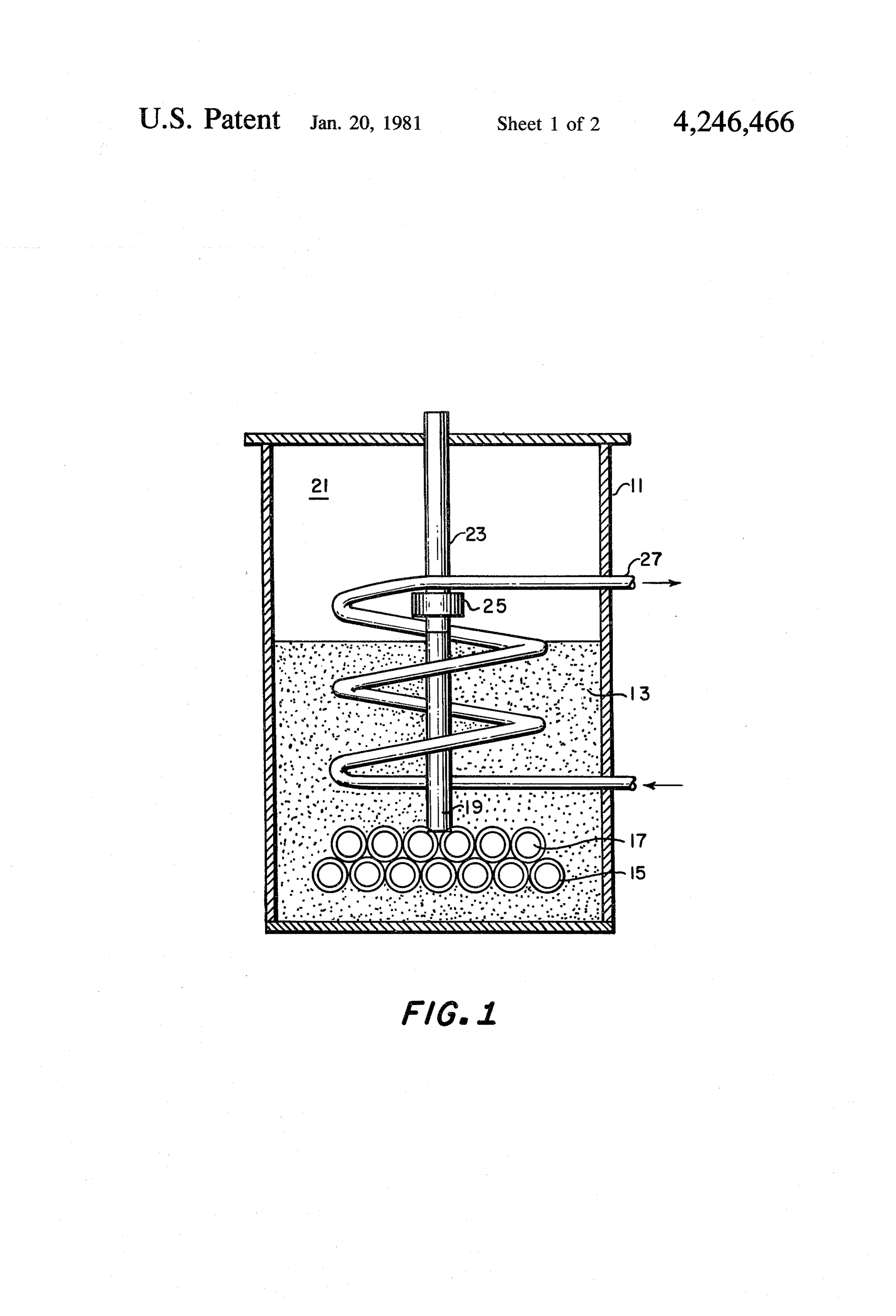
According to the present invention apparatus for tending through the side wall of tank 11. Tubes 17 con storing heat comprises a container having a bed of fus tain electrical heating elements, which may suitably ible heat storage medium therein; a main heating unit consist of quartz tubes 35 containing resistance elements located in the bottom portion of said container for heat 20 37. Electrical leads 39 and 41 extend to the outside of ing said bed of fusible medium above its melting point; tank 11 and are appropriately connected to a source of a first vertical heater located in said bed of fusible heat electrical current. It will be appreciated that, in case of storage material and in thermal contact with the main failure or malfunction of a heating element, the element heating unit, the active portion of said first vertical may be removed and replaced in horizontal heating heater extending upwardly from said main heating unit 25 tubes 17 without draining tank 11 and without serious substantially only to the height of the heat storage me disruption of the heating function of the unit. First verti dium in solid phase, and a second vertical heater located cal heater 19 is comprised of a hollow tube having a in said container and in thermal contact with said first closed bottom end 43 and open end 45 extending vertical heater, the active portion of said second heater through the top of tank 11. First vertical heater 19 is extending substantially only from the height of said heat 30 suitably fabricated of steel and is positioned in thermal storage medium in solid phase to the height of said heat contact with at least one horizontal heating tube 17. storage medium in liquid phase, said first and second First vertical heater 19 contains heating element 47 vertical heaters being independently energizable. which extends from the closed bottom of heater 19 to a DESCRIPTION OF THE INVENTION level adjacent to the height of heat storage medium 13 35 when the unit is discharged, as shown in FIG. 1. First
The present invention can best be understood by vertical heater 19 supplies heat only to the height of the reference to the accompanying drawings which are part solid heat storage medium. Therefore, the portion of the hereof and are hereby incorporated herein. protection tube which is exposed to the gas in clearance FIG. 1 is a diagrammatic view of a discharged tank of space 21 is not excessively heated. First vertical heater alkali metal hydroxide composition containing a main 40 19 is thermally connected to second vertical heater 23 heater assembly and an improved dual, independent, by metal link 25. Second vertical heater 23 is comprised vertical heater assembly of the present invention. of a hollow tube having a closed bottom end 49 and an FIG. 2 is a diagrammatic side view of the tank of open upper end 51 outside of tank 11. Second vertical FIG. 1 in a full charged condition. heater 23 houses a heating element 53 which extends FIG. 3 is a schematic diagram of the elements used to 45 from the closed bottom end 49 of second vertical heater energize and de-energize the heaters. 23 to a level adjacent to the level of the heat storage Looking now at FIG. 1, heat storage container, or medium when the unit is completely charged, as it is tank 11, suitably of a metal such as steel, contains heat shown in FIG. 2. The tube 23 is preferably constructed storage medium 13. Medium 13 operates on the heat of of an alloy such as Inconel or Monel which is resistant fusion principle. Suitably, the medium is an alkali metal 50 to corrosion and oxidation when the tube is exposed to hydroxide composition. Eminently suited is a commer the gas in clearance space 21 and when heating element cially available heat storage medium marketed under 53 is energized. Electrical leads 63 and 67 to heating the trademark Thermkeep. Thermkeep composition is elements 47 and 53 extend outside tank 11 and are ap an alkali metal hydroxide, alkali metal nitrate mixture propriately connected to a source of electrical current. which may contain corrosion inhibitors. As shown in 55 It will be appreciated that, in case of failure of elements FIG. 1, the heat storage unit is completely discharged, 47 and 53, repair or replacement may be carried out that is, the bed of heat storage medium 13 in tank 11 is without draining tank 11 or seriously interrupting the in a solid state at its lowest operating temperature. Posi heating function of the unit. Preferably elements 47 and tioned in the bottom portion of tank 11 is a main heating 53 are of an open coil design and would require minimal source comprised of a plurality of horizontal heating 60 clearance about the unit for removal and replacement. tubes 17 which may suitably be equipped with metal Alternatively, rigid elements 35 may be used. Tank 11 flanges 15 or a thermal connecting link to facilitate may be equipped with vent 55 to allow air to enter and good thermal connection between the tubes at one or leave the expansion space 21 during thermal cycling. more locations. A first vertical heater 19 is positioned Alternatively, the clearance space 21 may be sealed, as within tank 11 in thermal contact with at least one hori 65 described in U.S. Pat. No. 3,501,261. Zontal heating tube 17 and extends upward into expan In operation starting from a condition of minimum sion space 21. A second vertical heater 23 is thermally thermal charge as the unit is shown in FIG. 1, vertical connected to the first vertical heater 19 by means of heaters 19 and 23 are initially activated. Second vertical
Page 6
heater 23 is suitably controlled by a temperature sensor, ence has been made for purely illustrative purposes, and 60, such as a thermocouple positioned in the upper various modifications in the details therein included can portion of the unit, to remain energized until the tem be made without departing from the scope and spirit of perature of the medium exceeds its melting temperature. the invention as will be obvious to those of ordinary Horizontal heating tubes 17 may be activated simulta skill in this art.
neously with heaters 19 and 23, or a few minutes there We claim:
after to insure that an escape path has been established 1. An apparatus for storing heat comprising: for the liquid heat storage medium. When the melting a container having a bed of fusible heat storage me temperature has been exceeded in the vicinity of verti dium therein;
cal heater 23, it is deemergized. Vertical heater 19 and 10 a main heating unit located in the bottom portion of horizontal heating tubes 17 remain energized until sen said container for heating said bed of fusible me sor 61 indicates that the maximum desired temperature dium above its melting point; of the medium is reached in the vicinity of heating tubes a first vertical heater located in said bed of fusible 17. Thereafter vertical heater 19 and horizontal heating heat storage material and in thermal contact with tubes 17 are energized and de-energized simultaneously 15 the main heating unit, the active portion of said first as required, and vertical heater 23 is energized when the vertical heater extending upwardly from said main temperature of the surrounding medium approaches the heating unit substantially only to the height of the solidifying temperature range. heat storage medium in solid phase, and A preferred medium comprises 5% to 30% by weight a second vertical heater located in said container and of NaNO3, 0.1% to 0.5% MnO2, and the balance com 20 in thermal contact with said first vertical heater, mercial grade anhydrous NaOH (which may contain the active portion of said second heater extending small amounts of NaCl and Na2CO3). When using this substantially only from the height of said heat stor medium, the melting (and solidifying) range is approxi age medium in solid phase to the height of said heat mately 250° C. to 320° C., and the maximum operating storage medium in liquid phase, said first and sec temperature of the medium may be approximately 455" 25 ond vertical heaters being independently energiz C. able.
The operation of the system may be controlled by the 2. The apparatus of claim 1 wherein the heat storage elements shown in FIG. 3, in which a thermocouple medium is an alkali metal hydroxide composition. temperature sensor 60 actuates power controller 71 3. The apparatus of claim 2 wherein the alkali metal which energizes and de-energizes heater 53 as described 30 hydroxide composition is a sodium hydroxide composi above. A second thermocouple temperature sensor 61 tion.
actuates power controller 72, which energizes and de 4. The apparatus of claim 1 wherein said main heating energizes simultaneously vertical heater 47 and main unit is comprised of a plurality of generally horizontal heater 35 as described above. hollow metal tube members having one closed end It will be appreciated that exposure to the gas in 35 extending within said container and an open end extend clearance space 21 of the first and second vertical heat ing through the side wall of said container, said tube ers while energized is minimized. First vertical heater members containing electrical heating elements. 19 is not exposed, and exposure of the second vertical 5. The apparatus of claim 4 wherein said heating heater 23 is minimal. Second vertical heater 23 may elements are removable from the outside of said con suitably be fabricated of corrosion resistant metal such tainer.
as nickel, Iconel, or Monel to protect the heater from 6. The apparatus of claim 1 wherein the first and surface deterioration. second vertical heaters are metal tubes having a closed The invention described herein is applicable to phase bottom end and contain electrical heating elements. change heat storing media in general. Such media in 7. The apparatus of claim 6 wherein the upper ends of clude, among others, alkali and alkaline earth carbon 45 said metal tubes are open and extended above the height ates, chlorides, bromides, iodides, fluorides, hydroxides, of said bed of heat storage medium in liquid phase, nitrates, and nitrites; fusible metals; and fusible organic whereby said heating elements are removable at a point materials. The metals which are suitable include those above the level of said heat storage bed when said heat which are suitably compatible with the heat storage storage medium is in liquid phase.
media. Heaters may be energized by heat transfer fluids 50 8. The apparatus of claim 1 including a conduit in said as well as by electric heating elements. container in heat exchange relation with said bed of heat The present invention has been described and illus storage medium for the passage of a heat transfer me trated in the above specification and examples with dium through said container.
reference to several specific embodiments. Such refer k ski i k k
Provenance
- Collection
- Cited prior art
- Original PDF
- patentimages.storage.googleapis.com →
- Filed
- 1979-08-20
- Pages
- 6
- Method
- pdftotext (the PDF's own text layer) + pdftoppm 300dpi page scans
- Source
- Google Patents bibliographic record
- Granted
- 1981-01-20
- Inventors
- Richard E. Rice; Barry M. Cohen; George W. Webb; Hooker Chemicals and Plastics Corp
- Transcribed from
- patentimages.storage.googleapis.com →