patent · US3870855
Electric heating and battery charging system for motor vehicle
11 March 1975
Page 1 — bibliographic record
Edlund et al.
54) ELECTRIC HEATING AND BATTERY l,863,882 6/1932 Scharf.......................... 29/202 UX CHARGING SYSTEM FOR MOTOR 2,427,713 9/1947 Caldwell......................... 219/209 X WEHICLE 2,654,826 - 10/1953 Spurlin............. ... 29/205 X (75) Inventors: Lars Anders Edlund, Kalmar; Berth 2,819,373 lf 1958 Allman............................... 219/202
Atle Wikström, Ljungbyholm, both 3,673,379 6/1972 Eversull.............................. 219/202 of Sweden 73) Assignee: Berth Wikström AB, Slojdgatan, FOREIGN PATENTS OR APPLICATIONS Kalmar, Sweden 668,290 1 1/1938 Germany...................... 1231142.5 E 22 Filed: Jan. 23, 1974 Primary Examiner-A. Bartis 21 Appl. No.: 436,016 Attorney, Agent, or Firm-Sughrue, Rothwell, Mion, Zinn & Macpeak (30) Foreign Application Priority Data
Jan. 23, 1973 Sweden.............................. 7300890 (57) ABSTRACT
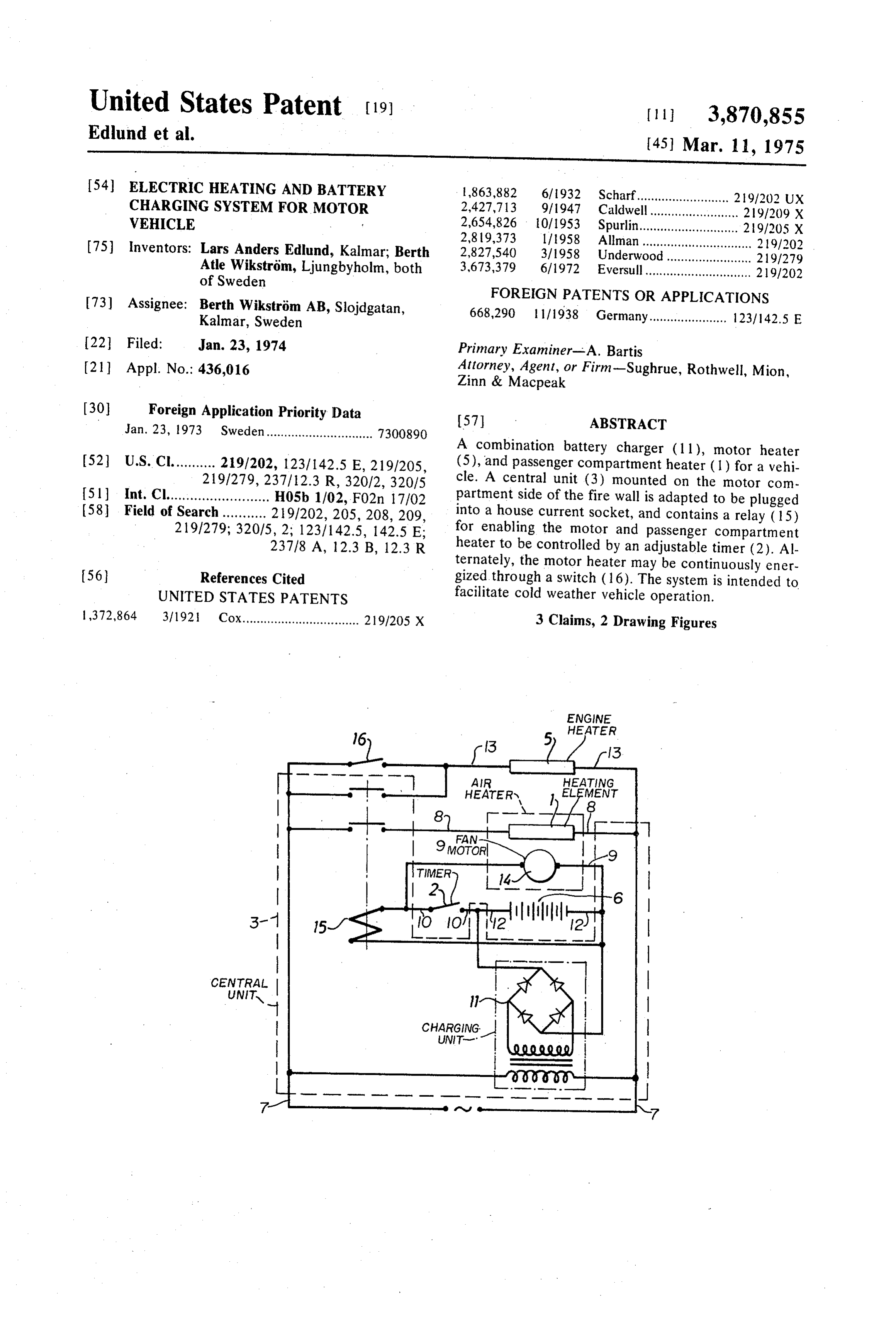
A combination battery charger (1 l), motor heater (52) U.S. Cl........... 219/202, 123/142.5 E, 219/205, (5), and passenger compartment heater (1) for a vehi 219/279, 237 / 12.3 R, 32012, 32015 cle. A central unit (3) mounted on the motor com 51 Int. Cl.......................... H05b 1/02, F02n 17102 partment side of the fire wall is adapted to be plugged (58 Field of Search ........... 219/202, 205, 208, 209, into a house current socket, and contains a relay (15) 2 191279; 32015, 2; 1231142.5, 142.5 E; for enabling the motor and passenger compartment 23718 A, 12.3 B, 12.3 R heater to be controlled by an adjustable timer (2). Al ternately, the motor heater may be continuously ener 56) References Cited gized through a switch (16). The system is intended to UNITED STATES PATENTS facilitate cold weather vehicle operation. 1,372,864 3/192 Cox................................. 219/205 X 3 Claims, 2 Drawing Figures
ENGINE
5 HEATER
HEArERs, ELFAENT
CENTRAL
UNITQ |
CHARGING.
Page 2
Drawing sheet — no readable text.
Page 3
ELECTRIC HEATING AND BATTERY CHARGING trolled by a timer permanently mounted in the vehicle. SYSTEM FOR MOTOR WEHICLE The timer, when starting operation of the heating ele BACKGROUND OF THE INVENTION ment via the relay, at the same time starts the fan motor 1. Field of the Invention by connecting it to the vehicle battery. Suitably the system is of the kind in which the central
This invention relates to a system for electrically unit also controls an electric heater for the vehicle mo heating a vehicle charging the vehicle electric battery. tor, the central unit being equipped with a manual 2. Description of the prior Art switch enabling the choice between timer controlled Electric heaters for the internal combustion engines operation of the motor heater simultaneously with the of motorcars are widely used. Such motor heaters are 10 air heater or continuous operation of the motor heater connected to the electric mains. In cold weather the during the whole motor heater is often connected to the electric mains nected to the mains. time during which the vehicle is con in the evening to keep the motor warm during the night According to a further embodiment of the invention and give an easy start in the morning.
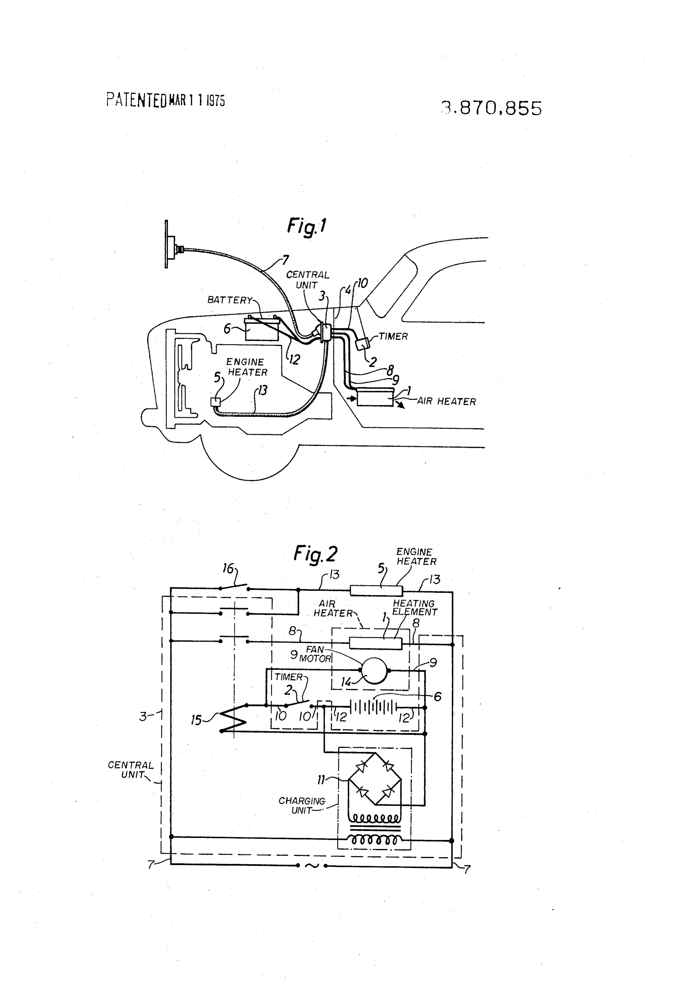
Recently electric passenger compartment heaters 15 the central unit is designed so as to be able to be mounted have been used for defrosting of the vehicles windows compartments on the wall between the motor and passenger and warming up the seats. Such heaters have hitherto tral unit-mounted the electric cables connecting the cen usually been designed for placing on the floor of the at the motor compartment side-- parked vehicle, although they have also been perma with the air heater and the timer-mounted at the pas nently mounted. senger compartment side of the wall-running from the The electric heaters have, however, such a high central unit directly through the partition wall or fire power consumption that a continuous connection to wall in such a way that no part of said cables has an the electric mains during the whole parking time, i.e. open location within the motor compartment. during the whole night, is too expensive. Therefore a BRIEF DESCRIPTION OF THE DRAWINGS timer has been used for starting the heater, for instance 25 FIG. 1 shows a heat system according to the inven 2 hours before the time when the vehicle is supposed to be used. In order to avoid a high-voltage installation tion in a car.
in the vehicle, the timer has usually been attached to a temFiG. 2 shows a circuit diagram adaptable to the sys according to FiG. 1 mains house wall socket-outlet.
When using the vehicle for short drives in winter time 30 DESCRIPTION OF THE PREFERRED with high power consumption for lamps, fans, etc. a EMBODIMENT periodic recharge of the electric battery of the vehicle is necessary. There are different types of battery char According to the arrangement shown in FIG. 1 the gers available in the market, which make it necessary electric heater 1 is mounted in the passenger compart to have the battery taken out of the vehicle, although 35 ment of the vehicle. In the passenger compartment a tedious electric connetion of the battery to the char there is also a timer 2 and suitably also a manual switch. ger is sometimes also possible. A central unit 3 is mounted on the wall 4 between the
SUMMARY OF THE INVENTION
motor compartment and the passenger compartment.
In the motor compartment the electric engine heater 5
The electric vehicle heating system according to the 40 and the electric battery 6 are mounted. When opeart present invention is in all its parts permanently ing the system the central unit 3 is connected to the mounted in the vehicle. By connecting the mains to the mains by means of a cable 7.
electric outlet of the vehicle, the vehicle battery will be The passenger compartment heater 1 is electrically charged during the whole time of connection, the 45 connected to the central unit 3 by means of a main volt motor will be heated either during the whole time of age cable 8 and also by means of a low voltage cable connection or during the time set on the timer, whereas 9. The timer 2 is also connected to the central unit 3 the passenger compartment be on only during the time by means of a low voltage cable 10, Charging of the set on the timer. The heating system according to the battery 5 is achieved by means of the charging unit 11 present invention is more easily operated than the con 50 of the central unit 3 via a cable 12. The motor heater ventional systems described above. Furthermore, the 5 is connected to the central unit 3 via the cable 13. system according to this invention presents a safer solu The circuit diagram according to FIG. 2 shows how tion because of the fact that the owner of the vehicle the charging unit 11 is connected to the battery 6. The only has one connection to the elctric mains and be timer 2 operates the relay 15 giving power to the engine cause the timer and the passenger compartment heater 55 heater 5 and the air heater 1, the fan motor 14 of said fan are operated at low voltage. heater being simultaneously started over the contact 2 The present invention thus mainly consists in a sys of the timer, the fan motor 13 being thus fed by DC tem for the electric heating of vehicles comprising a current. A very small motor with a high number of rev permanently mounted, fan operated warm air heater olutions (about 7000 r/m) may thus be used, resulting and a central unit containing a unit for charging the ve 60 in a small and efficient air heater. hicle electric battery. The charging unit is arranged What is claimed is:
when connecting the system to the electric mains im mediately and during the whole time of connection to for1.aAmotor combination battery charger and heater system charge the electric battery, whereas the heating ele gized by a vehicle, said system adapted to be ener conventional alternating current power ment of the air heater supplied from the mains is oper ated via a relay, the coil of said relay being operated 65 source
such as 115 volta, c. or the like, comprising:
warm air heater permanently mounted in the ve with low voltage from the charging unit (the vehicle hicle and including an electric heating element and battery,) the operation of the relay being further con an electric fan,
Page 4
b. a central control unit permanently mounted in the outside source of alternating current through the con vehicle and including: nector under control of the relay contacts of the central 1. an electric connector adapted to be connected control unit, said unit further comprising a manual to an outside source of alternating current, switch connected in parallel with the relay contacts to 2. a battery charger permanently coupled between thereby enable a choice between timer controlled oper the connector and the vehicle battery, and ation of the motor heater simultaneously with the warm 3. a relay coil and associated contacts for coupling air heater and continuous operation of the motor the electric heating element to the connector, heater during the whole time the system is operable. and 3. A system according to claim 1, wherein the central c. a timer permanently mounted in the vehicle and O control unit is mounted at a motor compartment side connected in series with the vehicle battery and the on a wall between a motor compartment and a passen : electric fan for energizing the fan with low voltage ger compartment of the vehicle, electrical cables con "DC power, the timer also being connected in series necting the unit with the air heater and the timer, both with the relay coil and the battery simultaneously mounted within the passenger compartment, said ca energizing the relay coil with low voltage DC 15 bles running from the unit directly through the wall into power. the passenger compartment such that no part of said 2. A system according to claim 1, further comprising cables are located within thek motor compartment. a vehicle motor heater adapted to be energized by the . .
Provenance
- Collection
- Cited prior art
- Original PDF
- patentimages.storage.googleapis.com →
- Filed
- 1974-01-23
- Pages
- 4
- Method
- pdftotext (the PDF's own text layer) + pdftoppm 300dpi page scans
- Source
- Google Patents bibliographic record
- Granted
- 1975-03-11
- Inventors
- Lars Anders Edlund; Berth Atle Wikstrom; BERTH WIKSTROM AB
- Transcribed from
- patentimages.storage.googleapis.com →