patent · US4369635
Subterranean heating and cooling system
25 January 1983
Page 1 — bibliographic record
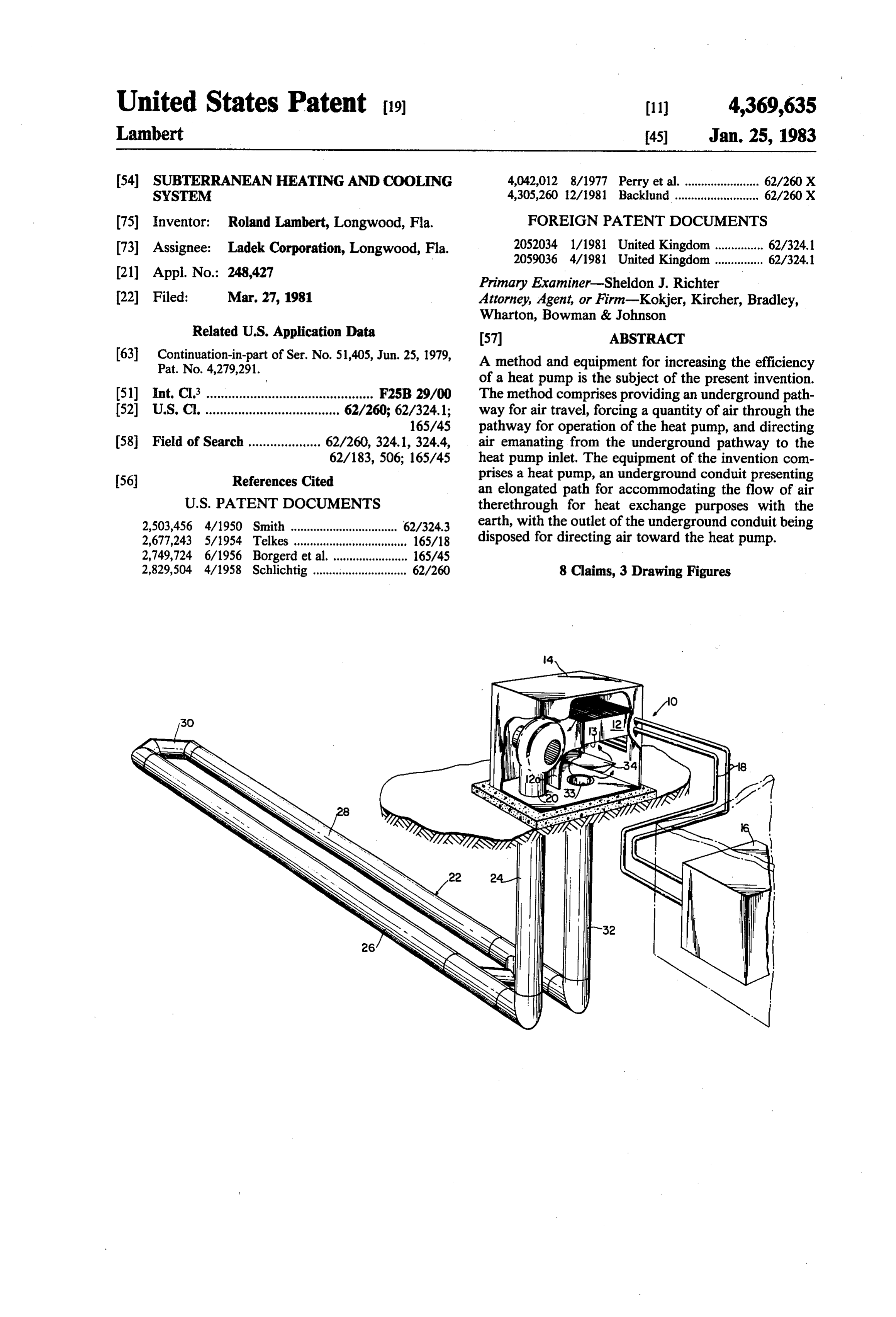
United States Patent 19 (11) 4,369,635 Lambert 45) Jan. 25, 1983 (54) SUBTERRANEAN HEATING AND COOLNG 4,042,012 8/1977 Perry et al. ....................... 62/260 X SYSTEM 4,305,260 12/1981 Backlund .......................... 62/260 X (75) Inventor: Roland Lambert, Longwood, Fla. FOREIGN PATENT DOCUMENTS (73) Assignee: Ladek Corporation, Longwood, Fla. 2052034 1/1981 United Kingdom............... 62/324.1
(21) Appl. No.: 248,427 Primary Examiner-Sheldon J. Richter (22) Filed: Mar. 27, 1981 Attorney, Agent, or Firm-Kokjer, Kircher, Bradley, Wharton, Bowman & Johnson
Related U.S. Application Data 57 ABSTRACT (63) Continuation-in-part of Ser. No. 51,405, Jun. 25, 1979, A method and equipment for increasing the efficiency
of a heat pump is the subject of the present invention.
(51) Int, C.3 ..... a use as w F2SB 29/00 The method comprises providing an underground path (52) U.S. C. ..................................... 62/260; 62/324.1; way for air travel, forcing a quantity of air through the 165/45 pathway for operation of the heat pump, and directing (58 Field of Search .................... 62/260, 324.1, 324.4, air emanating from the underground pathway to the 62/183, 506; 165/45 heat pump inlet. The equipment of the invention com 56) References Cited prises a heat pump, an underground conduit presenting an elongated path for accommodating the flow of air
2,503,456 4/1950 Smith ................................. 62/324.3 earth, with the outlet of the underground conduit being 2,677,243 5/1954 Telkes ................................... 165/18 disposed for directing air toward the heat pump. 2,749,724 6/1956 Borgerd et al.... ... 165/45 2,829,504 4/1958 Schlichtig im 62/260 8 Claims, 3 Drawing Figures
Page 2
Drawing sheet — no readable text.
Page 3
Other objects of the invention will be made clear or
SUBTERRANEAN HEATING AND COOLNG become apparent from the following description and - SYSTEM claims when read in light of the accompanying drawing wherein:
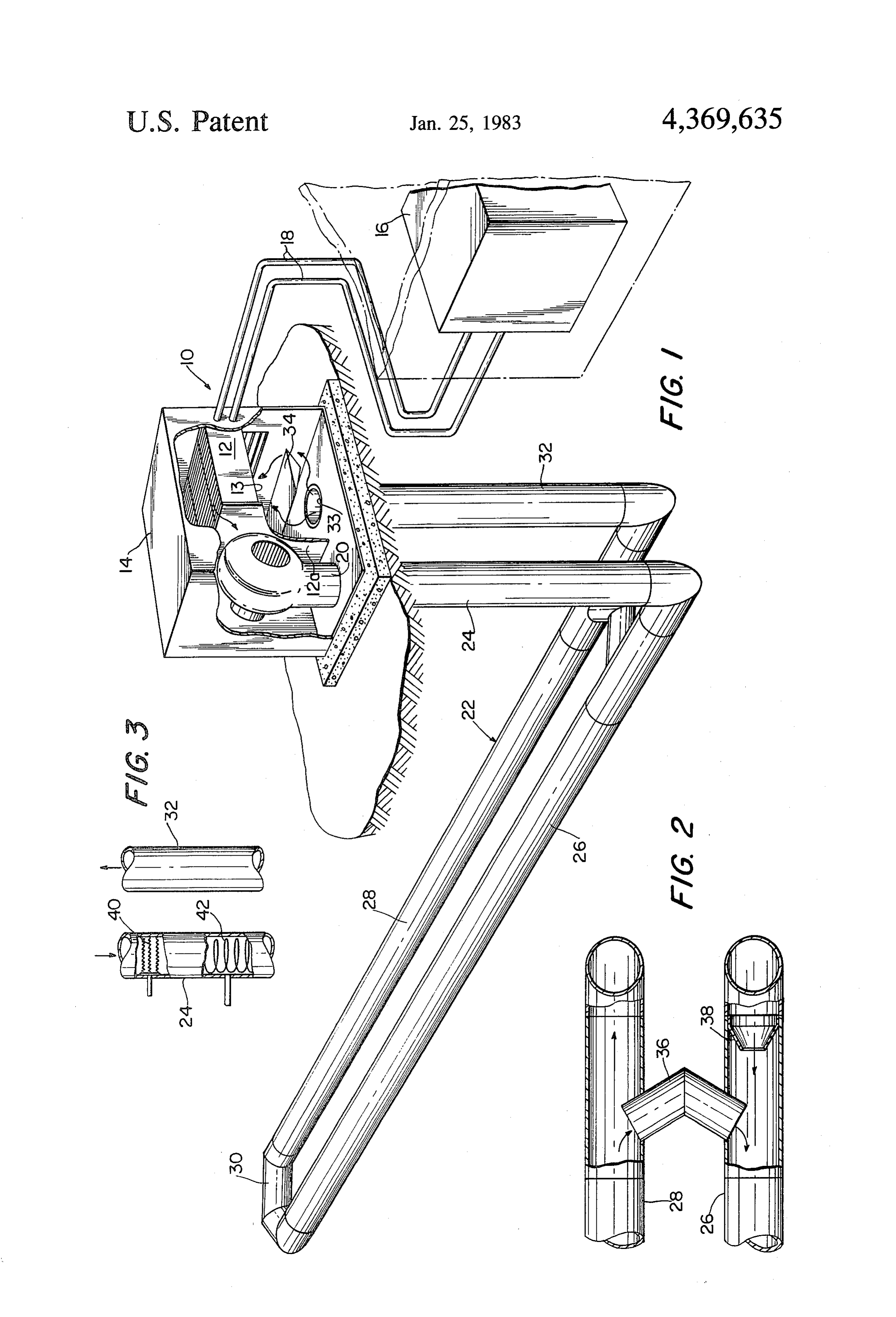
This is a continuation in part of my co-pending appli FIG. 1 is a perspective view of the heat pump system cation, Ser. No. 51,405, filed June 25, 1979, now U.S. according to the present invention; Pat. No. 4,279,291. FIG. 2 is a vertical cross-sectional view illustrating This invention relates in general to heating systems details of construction of the underground conduit and, more particularly, with an improved heat pump through which air passes; and and method of utilizing same. 10 FIG. 3 is a fragmentary elevational view showing an My co-pending application discloses and claims an alternative form of the invention.
improved subterranean heating and cooling system Referring initially to FIG. 1, the heating system of which has highly improved operating characteristics as the present invention is designated generally by the a result of a unique recycling feature. This feature al 15 numeral 10 and includes aheat pump 12 disposed within lows the length of the conduit to be substantially short a housing 14. The area of the heat pump inlet is desig ened while increasing the effective length of the path of nated by the number 13. The compressor for the heat travel of the air in heat exchange relationship with the pump 12 is located outside of the building inside of ground. housing 14 and an expansion coil for heat exchange with The utilization of heat pumps for heating buildings 20 air inside of the building is disposed in a second housing has been practiced for at least 20 years. The early heat 16. Insulated lines 18 carry the compressible heat ex pumps were little more than air conditioners which ran change liquid between the compressor and the expan in reverse. Many failures were recorded and the heat sionAncoil.
pump lost much of its market during the decade of the conduitauxiliary fan 20 is coupled with an underground designated generally by the numeral 22. Con 1960's. In more recent time, however, improved heat 25 duit 22 includes a first vertical leg 24 coupled directly pumps have resulted in a resurgence of the market. The continuing shortage of fossil based fuels has also in with the output of fan 20. Vertical leg 24 merges into a first horizontal stretch 26 which is coupled with a sec creased the demand. The basic problem encountered ond parallel horizontal stretch 28 by a U-shaped end with a heat pump is that its efficiency drops markedly as stretch 30. Horizontal stretch 28 is in communication the outside temperature drops. The Coefficient Of Per 30 with a second vertical leg 32 having its outlet 33 inside formance (COP) of a heat pump is likely to be in the of housing 14 and vicinity of 3 when the outside temperature is 50 F. This inlet for heat pumpdirectly in communication with the means that the heat pump will deliver 3 BTU's for serves to couple the outlet 33 with12atheofheat 12. Housing the heat pump pump inlet.
every BTU of electricity put into it. The same heat pump would likely have a COP of no greater than 2 35 duitReferring to FIG. 2, it is seen that a cross-over con 36 couples the two horizontal stretches 26 and 28.
when the mercury drops to the freezing point and at 15 One end of conduit 36 projects into conduit stretch 28 F., the COP would likely be mere 1. When tempera so as to present a deflector which will divert a portion tures of 15 F. or below are encountered, most heat of the air into the cross-over conduit. The opposite end pumps are provided with cutouts which will shut down of the cross-over conduit 36 projects into conduit the compressor or limit its operation and shift the major 40 stretch 26 providing a restrictor in this conduit which heating job to backup electrical resistance heaters. This, serves to increase the velocity of air in the vicinity of of course, dramatically increases the cost of operating the cross-over conduit. The velocity is further increased the heat pump and in fact makes its operation impracti by a venturi collar 38 disposed adjacent to the end of cal for many climates. It is also a major factor in limiting cross-over conduit 36 and slightly upstream from the the useful life of a heat pump. 45 latter. The increase in velocity in the vicinity of cross It is, therefore, a primary object of the present inven over conduit 36 causes a slight decrease in pressure tion to provide greater heat pump efficiency by precon inside of this conduit thereby enhancing the recycling ditioning the air from which heat is to be extracted by feature.
circulating it in heat exchange relationship with the During normal operation of the equipment of the ground prior to passing it through the heat pump. 50 present invention, the heat pump fan (not shown) which A major objective of the invention is to reduce the would normally form a part of the heat pump device is need for a heat pump to rely upon expensive auxiliary inactivated and replaced by auxiliary fan 20. Fan 20 is resistance heating by providing partially pre-heated air selected to have a capacity sufficient to supply the heat on which the heat pump acts to extract heat. pump with the needed volume of air for operation A primary aim of the invention is to increase the life 55 under selected conditions. Thus, fan 20 is activated to of a heat pump by reducing compressor operating time force air through conduit 22 where it will undergo heat as a result of pre-heating the air on which the compres exchange with the ground. The horizontal stretches of SOr acts. conduit 22 are disposed beneath the ground a sufficient It is also a principal objective of my invention to distance so that the temperature is substantially con provide a system of increasing heat pump efficiency by 60 stant. In most areas of the country, a temperature of utilizing pre-heated air on which the heat pump acts so 55°-60°. F. is obtained year-round at a depth of 3-10 as to make the heat pump utilizable in climates where it feet. By virtue of the cross-over conduit 36 and the has heretofore been impractical to do so. recycling feature attributable to it, the length of conduit A further aim of the invention is to provide a method 22 may be substantially reduced over what would oth of heating and cooling a building wherein the source of 65 erwise be required. A substantial portion of the total heating or cooling is located underground and the volume of air passing through the conduit is constantly ground is utilized as an energy storing sink from which recycled causing it to repeatedly be in heat exchange heating or cooling may be extracted as needed. relationship with the relatively warm surrounding
Page 4
ground. The air emanating from outlet 33 passes to the ing the steps of providing an underground pathway for inlet for the heat pump where the air is utilized to ex air travel, forcing a quantity of air through the pathway tract heat which is then transferred to the heat exchange for operation of the heat pump, and directing air ena coil inside of the building to be heated. nating from the underground pathway to the heat pump By virtue of the fact that air entering the heat pump where it is acted upon by the heat pump. The method inlet is substantially warmed over what would other includes coupling the underground conduit directly wise be encountered at normal outside temperatures, with the heat pump inlet and also locating the under the heat pump is required to work less to extract the ground pathway at a level beneath the surface of the desired amount of heat. This increases the efficiency of ground where the temperature is substantially constant. the heat pump and greatly reduces the need for reliance 10 Finally, it is within the scope of the present invention to upon auxiliary resistance heaters when the outside air include within the method steps the step of recycling a temperature drops substantially below freezing. In portion of the air traveling along the underground path many instances, the utilization of the method and equip way and increasing the velocity of the recycled air as ment of the present invention will result in the heat the latter commences travel along the pathway. pump being practical in cold climates where it other 15 I claim:
wise could not be economically utilized. 1. A method of operating a heat pump having only a An alternative form of the invention is illustrated in single inlet for air from which heat is to be extracted, FIG. 3. Construction of this embodiment is identical to said air inlet being disposed outside of a building to be the preferred embodiment described above except that heated or cooled, said method comprising: a heating element 40 and a cooling coil 42 are both 20 providing an underground pathway for air travel, disposed in first vertical leg 24. Heating element 40 is said pathway having an inlet and an outlet and coupled with an appropriate energy source and cooling being located at a level beneath the surface of the coil 42 is coupled with a compressor in a conventional ground where the temperature is substantially con manner. The term "heat exchanger' is used herein to stant;
refer generically to either heating element 40 or cooling 25 coupling said underground pathway outlet with said coil 42. Manifestly, when a heat exchanger is located in heat pump inlet whereby air for said heat pump is conduit 24, as shown in FIG. 3, it is not necessary to provided solely by said pathway; and forcing a have another heat exchanger in a conventional above quantity of air through said pathway for operation ground location. That is, the heat exchangers 40 and 42 of said heat pump.
take the place of the heat exchangers which would 30 2. Equipment for conditioning the air of a building to normally be present in either a heat pump, air condi bring the air to a desired temperature level, said equip tioner or other heating or cooling source. In the alterna ment comprising:
tive form of the invention, conduit 32 would be pro a heat pump having only a single inlet for air from vided with a "Y" or "T' coupling so that at least a which heat is to be extracted; portion of the air emanating from vertical conduit 32 is 35 an underground conduit presenting an elongated path directed across heat exchanger 40 or 42. The remainder accommodating the flow of air therethrough and of the air from conduit 32 may be passed directly into having an inlet end for receiving incoming air and the building. an outlet end for discharging air, said conduit ex It has been found that by placing the heat exchanger tending through the soil beneath the surface of the in the vertical conduit, the heat exchange unit may be 40 ground at a level where the temperature is substan operated for a relatively short period of time during tially constant;
which cold or heat will be transferred to the surround means for coupling said conduit outlet with said heat ing earth. The earth acts as a heat or cold sink where the pump inlet whereby air for said heat pump is pro energy may be stored until it is brought into the adja vided solely by said underground pathway; and cent building. In this manenr, the efficiency of the heat 45 means for forcing a quantity of air sufficient to oper exchanger is increased by warming or cooling the build ate said pump through said conduit. ing more gradually through the utilization of the 3. A method of operating a heat pump having an inlet method as herein disclosed than would be the case if the for air from which heat is to be extracted, said air inlet heating or cooling element was positioned for direct being disposed outside of a building to be heated or heat exchange with the building. Another advantage of 50 cooled, said method comprising:
the alternative embodiment of the invention is that the providing an underground pathway for air travel, heat exchanger may be operated during non-peak utility said pathway having an inlet and an outlet and demand periods thus lessening the demand load on the being located at a level beneath the surface of the utility and offering savings to the consumer. ground where the temperature is substantially con It should also be appreciated that the apparatus and 55 stant;
method of the present invention could find application forcing a quantity of air through said pathway for in conjunction with an underground system of the type operation of said heat pump;
disclosed in my co-pending application. By placing a directing air emanating from said underground path “y” in the conduit stretches 26 and 28 (or their vertical way outlet in the direction of said air inlet for said extensions), an auxiliary conduit may be run directly to 60 heat pump; and housing 16. An appropriate baffle will control air flow recycling a portion of the air traveling along said either to the inside housing 16 or the heat pump housing pathway.
14. When air is directed to the inside of the building, it 4. A method as set forth in claim 3, wherein said may be used as an independent cooling system or in directing step comprises coupling said underground conjunction with an air conditioner. 65 pathway outlet with said air inlet. From the foregoing, it will be apparent that the in 5. Equipment for conditioning the air of a building to vention encompasses a method of operating a heat bring the air to a desired temperature level, said equip pump which extracts heat from the outside air compris ment comprising;
Page 5
a heat pump having an inlet for air from which heat is means for effecting recycling of air passing through to be extracted; said conduit;
an underground conduit presenting an elongated path whereby air from which heat is to be extracted by accommodating the flow of air therethrough and 5 said heat pump is preconditioned by passage having an inlet end for receiving incoming air and through said underground conduit. 6. The invention of claim 5, wherein is included an outlet end for discharging air, said conduit ex means for coupling said conduit outlet with said heat tending through the soil beneath the surface of the pump inlet.
ground, 7. The invention of claim 5, wherein is included said outlet end of said conduit disposed for directing 10 means for increasing the velocity of air in said conduit air emanating therefrom toward said heat pump air in the vicinity of said recycling means. inlet; 8. The invention of claim 5, wherein said heat pump means for forcing a quantity of air sufficient to oper is disposed in said conduit.
ate said heat pump through said conduit; and
Provenance
- Collection
- Cited prior art
- Original PDF
- patentimages.storage.googleapis.com →
- Filed
- 1981-03-27
- Pages
- 5
- Method
- pdftotext (the PDF's own text layer) + pdftoppm 300dpi page scans
- Source
- Google Patents bibliographic record
- Granted
- 1983-01-25
- Inventors
- Roland Lambert; LADEK CORP
- Transcribed from
- patentimages.storage.googleapis.com →