patent · US4235224
Solar heat collector block
25 November 1980
Page 1 — bibliographic record
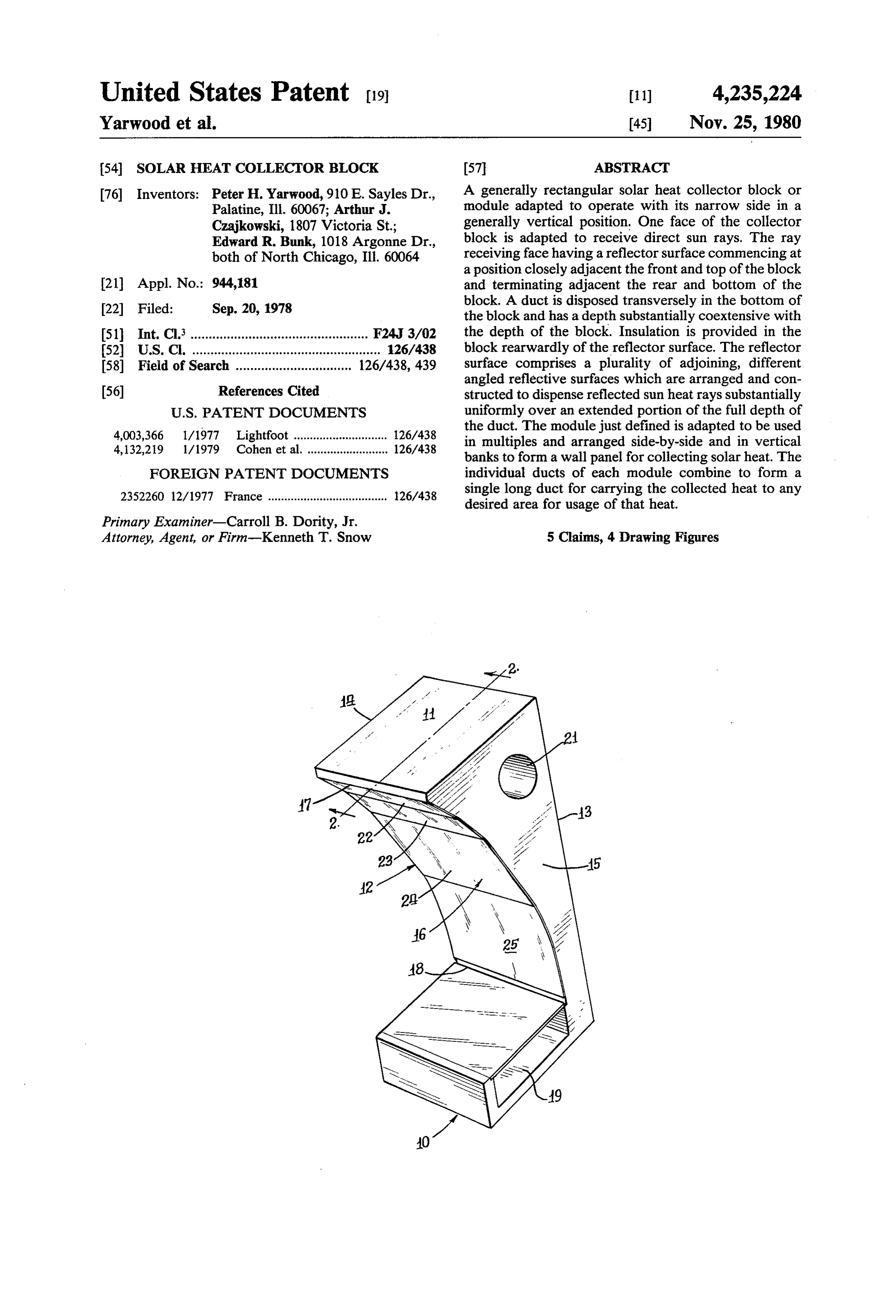
United States Patent (19) 11) 4,235,224 Yarwood et al. 45 Nov. 25, 1980 (54) SOLAR HEAT COLLECTOR BLOCK 57 ABSTRACT 76 Inventors: Peter H. Yarwood,910 E. Sayles Dr., A generally rectangular solar heat collector block or Palatine, Ill. 60067; Arthur J. module adapted to operate with its narrow side in a Czajkowski, 1807 Victoria St.; generally vertical position. One face of the collector Edward R. Bunk, 1018 Argonne Dr., block is adapted to receive direct sun rays. The ray both of North Chicago, Ill. 60064 receiving face having a reflector surface commencing at a position closely adjacent the front and top of the block 21 Appl. No.: 944,181 and terminating adjacent the rear and bottom of the 22 Filed: Sep. 20, 1978 block. A duct is disposed transversely in the bottom of the block and has a depth substantially coextensive with 51 Int. Cl. ................................................. F24J 3/02 the depth of the block. Insulation is provided in the 52 U.S.C. .................................................... 126/438 block rearwardly of the reflector surface. The reflector 58) Field of Search ................................ 126/438,439 surface comprises a plurality of adjoining, different angled reflective surfaces which are arranged and con 56) References Cited structed to dispense reflected sun heat rays substantially
4,003,366 1/1977 Lightfoot ............................. 126/438 the duct. The module just defined is adapted to be used 4,132,219 1/1979 Cohen et al. ......................... 126/438 in multiples and arranged side-by-side and in vertical banks to form a wall panel for collecting solar heat. The
FOREIGN PATENT DOCUMENTS individual ducts of each module combine to form a 23.52260 12/1977 France ..................................... 126/438 single long duct for carrying the collected heat to any desired area for usage of that heat.
Primary Examiner-Carroll B. Dority, Jr.
Attorney, Agent, or Firm-Kenneth T. Snow 5 Claims, 4 Drawing Figures
Page 2
Drawing sheet — no readable text.
Page 3
Drawing sheet — no readable text.
Page 4
over the three sides thereof not receiving the sun's re
SOLAR HEAT COLLECTOR BLOCK flected rays.
The disclosures discussed herein are all variations on
BACKGROUND OF THE INVENTION true parabolic curves and hence show some forms of 1. Field of the Invention spreading of reflected heat rays. However, no one of In recent years the utilization of solar heat has be them specifically spreads those reflected heat rays uni come more pronounced because of diminishing supplies formly over a substantial portion of the full depth of a of other forms of energy. Thus the harnessing of the duct to carry the heat to its ultimate use. sun's rays and particularly the efficient harnessing is O SUMMARY OF THE INVENTION becoming extremely important.
The development of means to collect heat from the vide A principal object of the present invention is to pro sun has taken many forms but in the main are unit pan a novel solar heat collector module. els, cells, or blocks which can be used either singly or in An important object of this invention is to provide a multiples. These unit panels have a sun reflecting sur 15 novel collector block for the sun's rays which reflect face for the concentration of the rays onto a heat col the full depthrays the received uniformly over a substantial portion of of a duct built into the collector block at lecting and transferring element. Most of the collector one end thereof.
panels of the past have employed reflective surfaces of Another important object of this invention is to pro parabolic curves where the sun's rays are all concen vide trated on a single point, or at the most a very limited 20 shapea which novel collector block of generally rectangular is adapted to be disposed in a generally area with attendant high heat. Heat losses tend to be vertical position with its narrow side up and a reflector greater when high heats are involved.
The present invention is designed with a reflector top and the front thereof tofrom surface therein extending
a position adjacent the position near the bottom surface capable of spreading the sun's rays over a sub and adjacent the rear thereof.
stantial area and at lower temperatures without exces 25 Still another important object of this invention is to sive heat losses to thereby better collect the gathered provide a novel collector block as established in the heat for transmission to the space to be heated. preceding object and having a generally rectangularly 2. Description of the Prior Art
A search of the prior art has been made and the fol shaped duct in the bottom thereof and the duct adapted lowing U.S. Pat. Nos. were believed to be pertinent 30 an extended uniformly to generally receive reflected heat rays over relative to applicants' invention of directing and spread the block to the rear ofitsthe portion of full depth from the front of block and this extended ing the sun's heat rays over an extended area of the full portion shiftable transversely across the full depth of depth of a heating duct. the duct in response to the angle of the solar rays re Von Brudersdorff 2,859,745 ceived by the reflector as caused by the changing posi Johnson, Jr.-3,285,333 35 tion of the sun throughout the day and throughout the Wartes-3,884,217 year.
Fallbel-3,923,039 Another and still further important object of this Spielberg-3,968,786 invention is to provide a novel collector block as de Smith-3,974,824 fined in the preceding two objects and in which the Cheng et al-3,982,527 reflector surface comprises adjoining multiple flat sur Rabl-3,991,740 faces disposed at different angles. Lightfoot-4,003,366 A still further important object of this invention is to Fattor-4,015,585 provide a novel solar heat block in which the reflector Cohen et al-4,022,188 surface and the duct therein are fully insulated over Parker-4,026,273 45 their non-ray receiving surfaces. All of the above listed U.S. patents are concerned Other and further important objects and advantages with reflectors designed to concentrate solar radiation will become apparent from the disclosures in the fol on a particular point of a heat collector. Most of them lowing specification and the accompanying drawings. show parabolic curves.
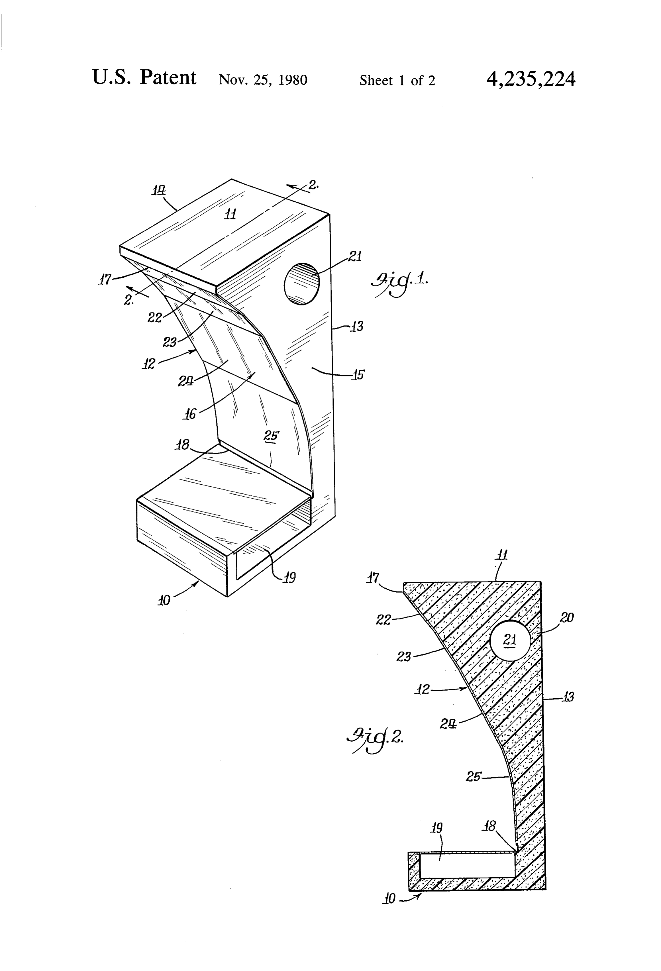
The patent to Fattor U.S. Pat. No. 4,015,585 employs 50 IN THE DRAWINGS a reflecting surface which focuses solar radiation into a FIG. 1 is a perspective view of the solar heat collec narrow, linear area rather than a single point as done tor block of this invention.
with a true parabolic reflector. FIG. 2 is a sectional view taken on the line 2-2 of The Falbel patent, U.S. Pat. No. 3,923,039 employs a FIG. 1.
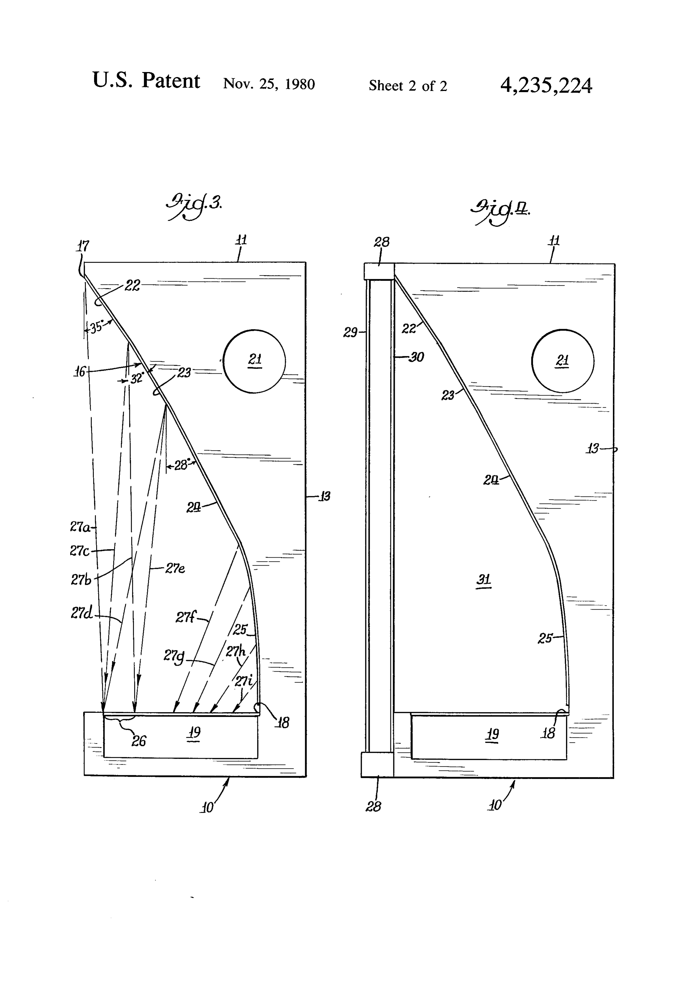
reflector which looks like a parabolic curve but is com 55 FIG. 3 is an enlarged side elevational view of the heat posed of curves of different radii and the focusing or collector block of FIGS. 1 and 2.
concentration of the sun's rays is not delivered to a FIG. 4 is a side elevational view similar to the device single point but rather has some spreading. shown in FIG.3 and having a front cover in association The Cohen et al patent, U.S. Pat. No. 4,022,188 therewith.
shows a reflector with a flat portion and a curved por 60 AS SHOWN IN THE DRAWINGS tion associated with a duct to be heated.
The Lightfoot patent, U.S. Pat. No. 4,003,366 dis The reference numeral 10 indicates generally a base closes a reflector in the form of a hyperbolic curve and of the solar heat collector block of this invention. The has a triangularly shaped non-insulated duct to be block includes a top 11, a front surface 12, a generally heated, disposed intermediate the ends of the reflector. 65 flat rear surface 13, a first side 14 and a laterally spaced Lightfoot distinguishes from applicants' invention apart other side 15. A reflector 16, preferably of thin which carries a duct to be heated at one end of the highly polished metal, is mounted on the front surface reflector surface so that the duct can be and is insulated 12 of the block or cell and is adapted to receive and
Page 5
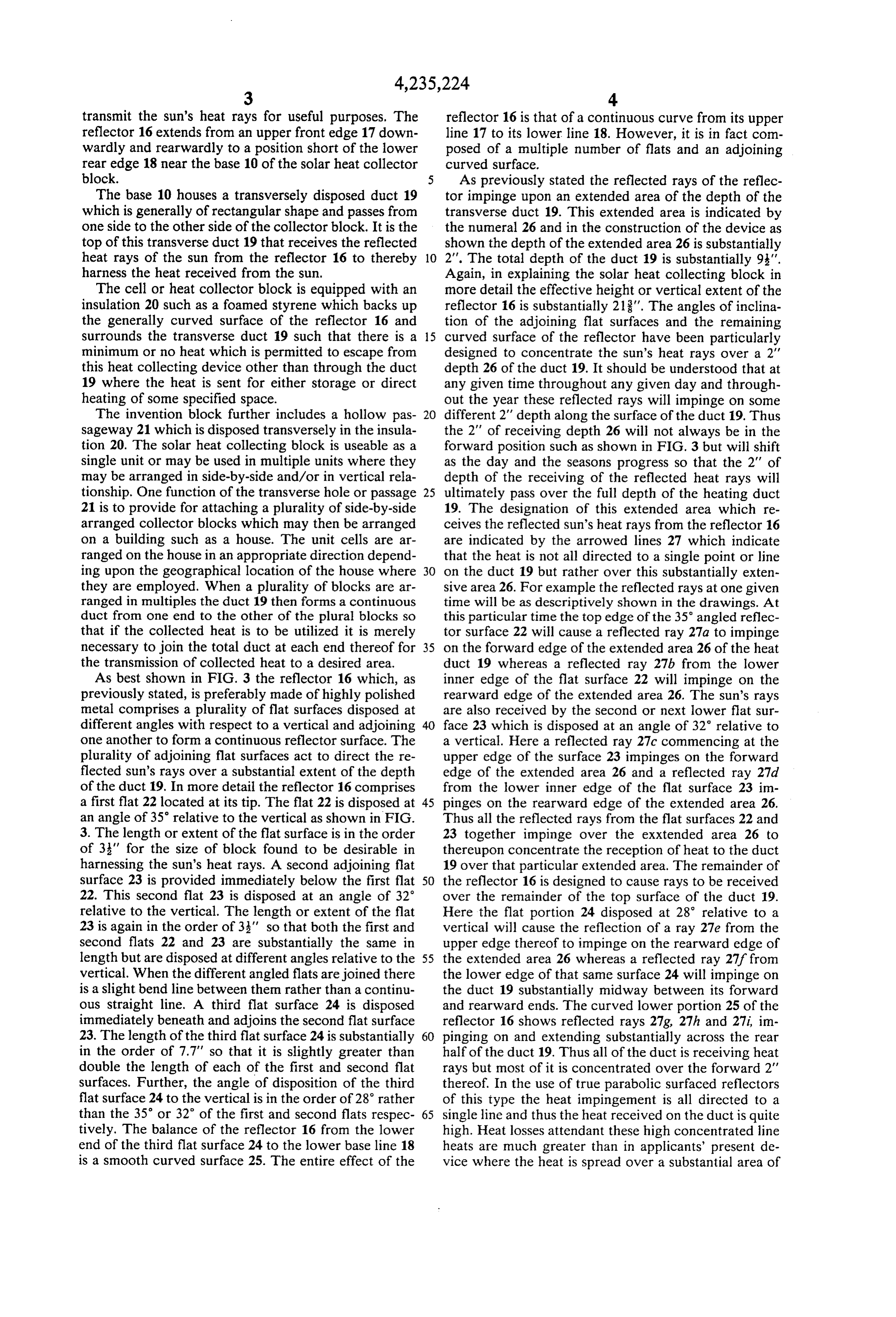
transmit the sun's heat rays for useful purposes. The reflector 16 is that of a continuous curve from its upper reflector 16 extends from an upper front edge 17 down line 17 to its lower line 18. However, it is in fact com wardly and rearwardly to a position short of the lower posed of a multiple number of flats and an adjoining rear edge 18 near the base 10 of the solar heat collector curved surface.
block. 5 As previously stated the reflected rays of the reflec The base 10 houses a transversely disposed duct 19 tor impinge upon an extended area of the depth of the which is generally of rectangular shape and passes from transverse duct 19. This extended area is indicated by one side to the other side of the collector block. It is the the numeral 26 and in the construction of the device as top of this transverse duct 19 that receives the reflected shown the depth of the extended area 26 is substantially heat rays of the sun from the reflector 16 to thereby 10 2'. The total depth of the duct 19 is substantially 9:". harness the heat received from the sun. Again, in explaining the solar heat collecting block in The cell or heat collector block is equipped with an more detail the effective height or vertical extent of the insulation 20 such as a foamed styrene which backs up reflector 16 is substantially 218". The angles of inclina the generally curved surface of the reflector 16 and tion of the adjoining flat surfaces and the remaining surrounds the transverse duct 19 such that there is a 15 curved surface of the reflector have been particularly minimum or no heat which is permitted to escape from designed to concentrate the sun's heat rays over a 2' this heat collecting device other than through the duct depth 26 of the duct 19. It should be understood that at 19 where the heat is sent for either storage or direct any given time throughout any given day and through heating of some specified space. out the year these reflected rays will impinge on some The invention block further includes a hollow pas 20 different 2" depth along the surface of the duct 19. Thus sageway 21 which is disposed transversely in the insula the 2' of receiving depth 26 will not always be in the tion 20. The solar heat collecting block is useable as a forward position such as shown in FIG. 3 but will shift single unit or may be used in multiple units where they as the day and the seasons progress so that the 2' of may be arranged in side-by-side and/or in vertical rela depth of the receiving of the reflected heat rays will tionship. One function of the transverse hole or passage 25 ultimately pass over the full depth of the heating duct 21 is to provide for attaching a plurality of side-by-side 19. The designation of this extended area which re arranged collector blocks which may then be arranged ceives the reflected sun's heat rays from the reflector 16 on a building such as a house. The unit cells are ar are indicated by the arrowed lines 27 which indicate ranged on the house in an appropriate direction depend that the heat is not all directed to a single point or line ing upon the geographical location of the house where 30 on the duct 19 but rather over this substantially exten they are employed. When a plurality of blocks are ar sive area 26. For example the reflected rays at one given ranged in multiples the duct 19 then forms a continuous time will be as descriptively shown in the drawings. At duct from one end to the other of the plural blocks so this particular time the top edge of the 35 angled reflec that if the collected heat is to be utilized it is merely tor surface 22 will cause a reflected ray 27a to impinge necessary to join the total duct at each end thereof for 35 on the forward edge of the extended area 26 of the heat the transmission of collected heat to a desired area. duct 19 whereas a reflected ray 27b from the lower As best shown in FIG. 3 the reflector 16 which, as inner edge of the flat surface 22 will impinge on the previously stated, is preferably made of highly polished rearward edge of the extended area 26. The sun's rays metal comprises a plurality of flat surfaces disposed at are also received by the second or next lower flat sur different angles with respect to a vertical and adjoining face 23 which is disposed at an angle of 32 relative to one another to form a continuous reflector surface. The a vertical. Here a reflected ray 27c commencing at the plurality of adjoining flat surfaces act to direct the re upper edge of the surface 23 impinges on the forward flected sun's rays over a substantial extent of the depth edge of the extended area 26 and a reflected ray 27d of the duct 19. In more detail the reflector 16 comprises from the lower inner edge of the flat surface 23 im a first flat 22 located at its tip. The flat 22 is disposed at 45 pinges on the rearward edge of the extended area 26. an angle of 35 relative to the vertical as shown in FIG. Thus all the reflected rays from the flat surfaces 22 and 3. The length or extent of the flat surface is in the order 23 together impinge over the exxtended area 26 to of 3' for the size of block found to be desirable in thereupon concentrate the reception of heat to the duct harnessing the sun's heat rays. A second adjoining flat 19 over that particular extended area. The remainder of surface 23 is provided immediately below the first flat 50 the reflector 16 is designed to cause rays to be received 22. This second flat 23 is disposed at an angle of 32 over the remainder of the top surface of the duct 19. relative to the vertical. The length or extent of the flat Here the flat portion 24 disposed at 28 relative to a 23 is again in the order of 3' so that both the first and vertical will cause the reflection of a ray 27e from the second flats 22 and 23 are substantially the same in upper edge thereof to impinge on the rearward edge of length but are disposed at different angles relative to the 55 the extended area 26 whereas a reflected ray 27f from vertical. When the different angled flats are joined there the lower edge of that same surface 24 will impinge on is a slight bend line between them rather than a continu the duct 19 substantially midway between its forward ous straight line. A third flat surface 24 is disposed and rearward ends. The curved lower portion 25 of the immediately beneath and adjoins the second flat surface reflector 16 shows reflected rays 27g, 27h and 27i, im 23. The length of the third flat surface 24 is substantially 60 pinging on and extending substantially across the rear in the order of 7.7" so that it is slightly greater than half of the duct 19. Thus all of the duct is receiving heat double the length of each of the first and second flat rays but most of it is concentrated over the forward 2' surfaces. Further, the angle of disposition of the third thereof. In the use of true parabolic surfaced reflectors flat surface 24 to the vertical is in the order of 28' rather of this type the heat impingement is all directed to a than the 35 or 32 of the first and second flats respec 65 single line and thus the heat received on the duct is quite tively. The balance of the reflector 16 from the lower high. Heat losses attendant these high concentrated line end of the third flat surface 24 to the lower base line 18 heats are much greater than in applicants' present de is a smooth curved surface 25. The entire effect of the vice where the heat is spread over a substantial area of
Page 6
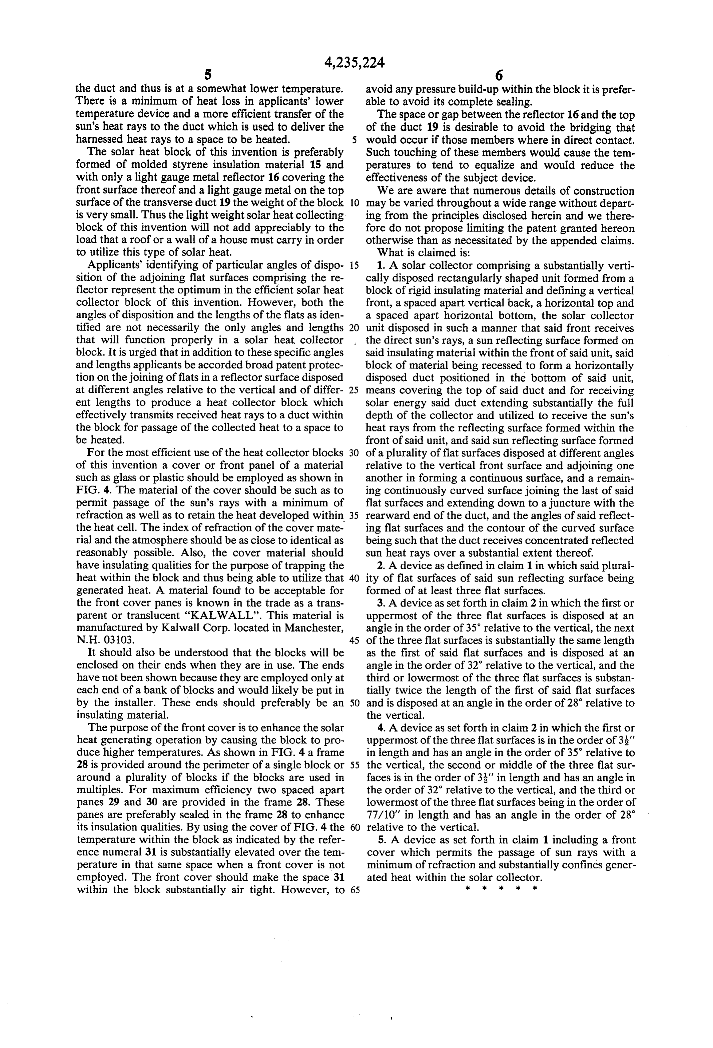
the duct and thus is at a somewhat lower temperature. avoid any pressure build-up within the block it is prefer There is a minimum of heat loss in applicants' lower able to avoid its complete sealing.
temperature device and a more efficient transfer of the The space or gap between the reflector 16 and the top sun's heat rays to the duct which is used to deliver the of the duct 19 is desirable to avoid the bridging that harnessed heat rays to a space to be heated. would occur if those members where in direct contact. The solar heat block of this invention is preferably Such touching of these members would cause the tem formed of molded styrene insulation material 15 and peratures to tend to equalize and would reduce the with only a light gauge metal reflector 16 covering the effectiveness of the subject device. front surface thereof and a light gauge metal on the top We are aware that numerous details of construction surface of the transverse duct 19 the weight of the block 10 may be varied throughout a wide range without depart is very small. Thus the light weight solar heat collecting ing from the principles disclosed herein and we there block of this invention will not add appreciably to the fore do not propose limiting the patent granted hereon load that a roof or a wall of a house must carry in order otherwise than as necessitated by the appended claims. to utilize this type of solar heat. What is claimed is:
Applicants' identifying of particular angles of dispo 15 1. A solar collector comprising a substantially verti sition of the adjoining flat surfaces comprising the re cally disposed rectangularly shaped unit formed from a flector represent the optimum in the efficient solar heat block of rigid insulating material and defining a vertical collector block of this invention. However, both the front, a spaced apart vertical back, a horizontal top and angles of disposition and the lengths of the flats as iden a spaced apart horizontal bottom, the solar collector tified are not necessarily the only angles and lengths unit disposed in such a manner that said front receives that will function properly in a solar heat collector the direct sun's rays, a sun reflecting surface formed on block. It is urged that in addition to these specific angles said insulating material within the front of said unit, said and lengths applicants be accorded broad patent protec block of material being recessed to form a horizontally tion on the joining of flats in a reflector surface disposed disposed duct positioned in the bottom of said unit, at different angles relative to the vertical and of differ 25 means covering the top of said duct and for receiving ent lengths to produce a heat collector block which solar energy said duct extending substantially the full effectively transmits received heat rays to a duct within depth of the collector and utilized to receive the sun's the block for passage of the collected heat to a space to heat rays from the reflecting surface formed within the be heated. front of said unit, and said sun reflecting surface formed For the most efficient use of the heat collector blocks of a plurality of flat surfaces disposed at different angles of this invention a cover or front panel of a material relative to the vertical front surface and adjoining one such as glass or plastic should be employed as shown in another in forming a continuous surface, and a remain FIG. 4. The material of the cover should be such as to ing continuously curved surface joining the last of said permit passage of the sun's rays with a minimum of flat surfaces and extending down to a juncture with the refraction as well as to retain the heat developed within 35 rearward end of the duct, and the angles of said reflect the heat cell. The index of refraction of the cover mate ing flat surfaces and the contour of the curved surface rial and the atmosphere should be as close to identical as being such that the duct receives concentrated reflected reasonably possible. Also, the cover material should sun heat rays over a substantial extent thereof. have insulating qualities for the purpose of trapping the 2. A device as defined in claim 1 in which said plural heat within the block and thus being able to utilize that ity of flat surfaces of said sun reflecting surface being generated heat. A material found to be acceptable for formed of at least three flat surfaces. the front cover panes is known in the trade as a trans 3. A device as set forth in claim 2 in which the first or parent or translucent "KALWALL'. This material is uppermost of the three flat surfaces is disposed at an manufactured by Kalwall Corp. located in Manchester, angle in the order of 35 relative to the vertical, the next N.H. O303. 45 of the three flat surfaces is substantially the same length It should also be understood that the blocks will be as the first of said flat surfaces and is disposed at an enclosed on their ends when they are in use. The ends angle in the order of 32 relative to the vertical, and the have not been shown because they are employed only at third or lowermost of the three flat surfaces is substan each end of a bank of blocks and would likely be put in tially twice the length of the first of said flat surfaces by the installer. These ends should preferably be an 50 and is disposed at an angle in the order of 28 relative to insulating material. the vertical.
The purpose of the front cover is to enhance the solar 4. A device as set forth in claim 2 in which the first or heat generating operation by causing the block to pro uppermost of the three flat surfaces is in the order of 3' duce higher temperatures. As shown in FIG. 4 a frame in length and has an angle in the order of 35 relative to 28 is provided around the perimeter of a single block or 55 the vertical, the second or middle of the three flat sur around a plurality of blocks if the blocks are used in faces is in the order of 33' in length and has an angle in multiples. For maximum efficiency two spaced apart the order of 32 relative to the vertical, and the third or panes 29 and 30 are provided in the frame 28. These lowermost of the three flat surfaces being in the order of panes are preferably sealed in the frame 28 to enhance 77/10" in length and has an angle in the order of 28 its insulation qualities. By using the cover of FIG. 4 the 60 relative to the vertical.
temperature within the block as indicated by the refer 5. A device as set forth in claim 1 including a front ence numeral 31 is substantially elevated over the tem cover which permits the passage of sun rays with a perature in that same space when a front cover is not minimum of refraction and substantially confines gener employed. The front cover should make the space 31 ated heat within the ksolar collector. within the block substantially air tight. However, to 65 k ck k ck
Provenance
- Collection
- Cited prior art
- Original PDF
- patentimages.storage.googleapis.com →
- Filed
- 1978-09-20
- Pages
- 6
- Method
- pdftotext (the PDF's own text layer) + pdftoppm 300dpi page scans
- Source
- Google Patents bibliographic record
- Granted
- 1980-11-25
- Inventors
- Peter H. Yarwood; Arthur J. Czajkowski; Edward R. Bunk
- Transcribed from
- patentimages.storage.googleapis.com →