patent · US1678711
Solar-heat drier
31 July 1928
Page 1
Drawing sheet — no readable text.
Page 2
Patented July 31, 1928. 1,678,711
UNITED STATES PATENT OFFICE.
LEWIS H. SHIPMAN, OF BOSTON, MASSACHUSETTS,
SOLAR-HEAT DRIER.
Application filed May 6, 1925. Serial No. 28,400.
My invention relates to driers and particu mediate rollersthe drums 4 and 5, by a series of larly to a drier for peat, fruit, and like ma Smaller on frame 1.
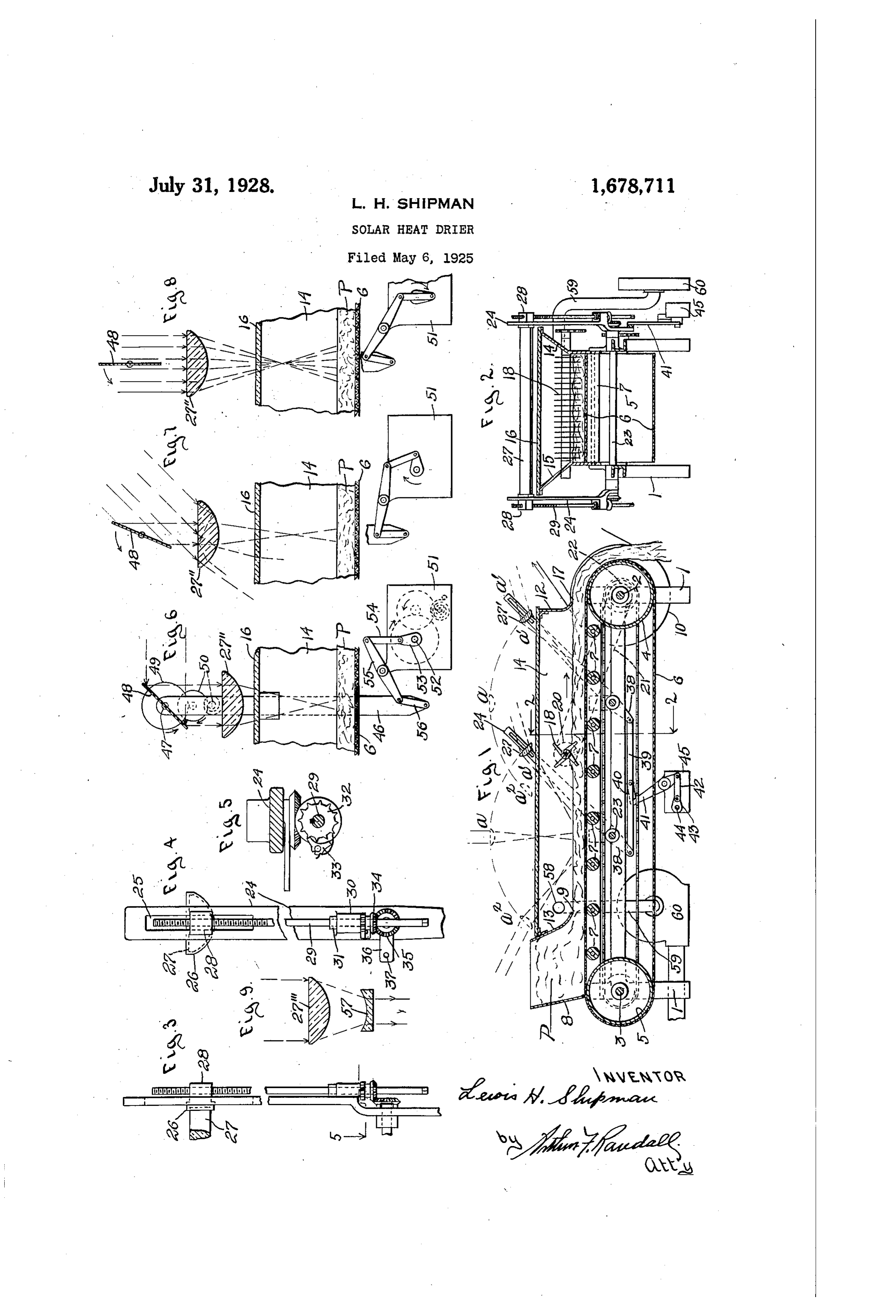
7 whose shafts are journaled terial, which utilizes heat derived from the Above the upper stretch of conveyer 6 and sun's rays. near one end thereof is a hopper 8 for hold 60 My improved drier comprises an endless ing traveling conveyer upon which is deposited beinga supply delivered of peat or the like, the latter from the hopper on to the the material to be dried, and adjacent the conveyer by gravity and one wall of the hop path of said conveyer is disposed means for er being made with an outlet opening 9 concentrating the solar rays upon the mate- throughp which the peat is carried by the ) rial on the conveyer, said material being car movement of the conveyer in the direction ried past said means from a loading position indicated by the arrow in Fig.
to a position where it is removed from the 2 of the drim 4 carries a pulley1.10 The shaft connected conveyer. In the best form of my inven tion the traveling conveyer constitutes the by which a belt with a source of rower through the conveyer is driven in the direction bottom wall of a housing that incloses the indicated.
material carried by the conveyer, said hous ing having a top wall made of glass or other theThe top stretch of conveyer 6 constitutes suitable transparent material through which the peat onwall bottom of a housing that incloses the sunlight is free to pass. - from the hopper 8conveyer the to the while it travels 75 drum 4, and this
Another feature of my invention, in its housing is completed by end walls best form, resides in the combination with 13, two outwardly inclined side walls12,14 and and
the traveling conveyer, of a lens for direct 15 and a top wall 16, the latter being made ing a beam of condensed solar rays upon the from glass or other suitable transparent ma material that is supported by the conveyer, and all of these walls being part of, 80 25 said lens being adjustable so that it may be terial, maintained in effective position between the wall 12 is made,by,adjacent or supported the frame 1. The end
Sun and the material on the conveyer outlet opening 17 for the drum 4, with an throughout the day. Preferably automatic enters the housing from the hopperThe peat. peat through 85 orientating means is provided for adjusting the passage 9 ???? during its travel through 30 the lens in this fashion.
Other features of my invention are herein the tion housing it is subjected to the drying ac of the heat of the sun's rays. After after pointed out. leaving the housing at exit 17 it is dis In the accomnanying drawings:
Figure 1 is a longitudinal sectional view charged latter by gravity from the conveyer as the 90 makes its turn around the drum 4, as 35 of a drier constructed in accordance with my shown in Fig. 1.
invention. Within the housing is arranged a rotatable Figure 2 is a section on line 2-2 of Fig. 1. beater
Figures 3, 4 and 5 are details relating to ings on18sidewhose shaft is journaled in bear the lens supporting means of the apparatus side the housing, a14pulley walls and 15 and carries, out 95 20 driven through 40 shown in Fig. 1. . a belt 21 by a pulley 22 fast on the shaft 2 Figures 6, 7 and 8 are elevations, partly in of drum 4. This beater serves section and more or less diagrammatic, ill peat on conveyer 6 over after the to top turn the portion lustrating a modification. - thereof has been subjected to the action of 00 Figure 9 is a detail illustrating another the sun's rays for a neriod of time. 45 modification. At a point intermediate beater 18 and My improved drier, as herein shown, com hopper 8 is a transverse shaft 23 journaled prises a frame 1, on which are journaled two in bearings shafts 2 and 3, one near each end thereof, fast thereon,on frame 1 said shaft having outside of the housing, two up 05 said shafts carrying drums or rolls 4 and 5, wardly extending arms 24, each formed near 50 respectively, which support an endless flexi its upper end with a longitudinal slot 25, ble conveyer belt 6 made from woven wire Figs. 3 and 4, within which is slidably fabric, or other suitable porous material. mounted a bracket 26, these two brackets The upper horizontal stretch of belt 6 re being attached rigidly to the opposite ends of O ceives upon it the peat or the like that is to a transversely disposed plano-convex-cylin 55 be dried, and this stretch is supported, inter
Page 3
drical lens 27 supported in position above It will be??parent that during each vi the housing by the arms 24. Each bracket bratory movement of each lens support the 26 is made, outside of its arm 24, with a lug gear 34 is rolled around the stationary gear 28 formed with a threaded hole through it 35 and as a result the pawl carrying arm pro to receive the upper end of a screw threaded jecting from gear 34 is vibrated with the re 70 rod or shaft 29. Near its lower end the shaft sult 29 is journaled in a bearing lug 30 provided screwthat pawl 88 imparts to ratchet 82 and 29 a rotative step movement and this upon the outer side of its arm and has fixed movement of the screw adjusts the lens to on it a collar 31 that is seated upon said ward or from the conveyer a predetermined 0 lug. Fast on shaft 29, just below lug 30, distance according to the setting of the re is a ratchet wheel32, Figs. 4 and 5, engaged versible pawl 33. This mechanism, the use by a reversible spring pressed pawl 33 car. of which is optional, is herein utilized to po ried by, an arm projecting from the hub of sition the lens nearest the conveyer in the a gear 34. The gear 34 is in mesh with a spring and to adjust the lens away from the 5 stationarily supported gear 35 that is loosely conveyer as the season progresses to mid mounted on the end of shaft 23 but held
against rotation therewith by an arm 36 Summer. At mid-summer the pawl 33 is manually or otherwise reversed after which projecting from the hub thereof and fastened the mechanism acts to shift the lens toward at 37 to the frame of the machine. the conveyer as the season progresses. 20 In the embodiment of my invention here In Figs. 6, 7 and 8 II have shown a modifi 85 in illustrated I have shown a second lens 27. cation disposed above the conveyer 6 and the hous its end wherein each lens, as 27', is fixed at to an upright bar 46 mounted upon ing intermediate the beater or stirrer 18 and the frame of the machine. At its upper end the outlet end of the housing, said lens'27' the bar 46 carries a shaft or trunnion 47 to 25 being likewise supported by a swinging lens which is secured one end of a reflector 48 90 R? including another shaft 23 jour which may be made of the same width and 8. ed on the main frame 1.
Arms 38 projecting downwardly from the gear length as the lens 2.7'. Shaft 47 carries a pivoted lens supports are joined by a con and rotated49 through, which it is connected with, 30 necting bar 39 connected through a link 40, once in forty-eight hours by, a clock mechainsm 50...Both sides of reflector lever 41, link 42 and arm 43 with the shaft 48 are mirrors and the movement of said 44 of a clock mechanism 45, said shaft mak reflector is timed so that at sun-rise it ing one revolution, every twenty-four hours. occupies the position shown in Fig. 6; at This clock mechanism acts through the con mid-day the position shown in Fig. 8 and at nections just described to vibrate the pivoted lens supports once every twenty Sun-Set a position ninety degrees from that 00 four hours and is timed so that at mid with this Fig.
shown in form 6. It will thus be clear that of my invention only the day the two lenses 27 and 27 occupy mirror 48 is adjusted intermediate positions a, a ; at sun-set the movement of the angularly to follow sun and that said 40 they occupy the positions a, a and at mirror serves to reflect a beam of rays 05 sun-rise they occupy the positions a”, a”. through lens 27' in a direction perpendicular The apparatus is placed in position where to the plane side thereof.
its conveyer 6 extends east and west and It may be desirable in some instances to preferably with its material receiving end mount the bar, 46 in vertical ways on the 45 toward the west. Thus it will be seen that throughout the day the two lenses will frame of the machine and to adjust the bar 110 be outomatically maintained in effective posi forenoon away and lens from the material as the tion between the sunt and the material upon terial as the afternoonand progresses toward the ma the conveyer. 6 and each will operate to di in shown I have provided a clockAsmech progresses. here 50 rect onto said i material a condensed beam anism 51 for automatically effecting this of Solar rays, the material being first sub jected to the action of the beam from lens adjustment, 52 making said mechainsm having a shaft.
one revolution every twenty-four 27; then turned over by the beater or stirrer hours an connected 18 and then subjected to the action of the bar 46 through an armwith 53 the lower end of fast on shaft 52; 20 55, beam from lens 27 after which it is dis a link 54; lever 55 and link 56. charged by gravity from the conveyer as the As shown in Fig. 9 the condensing lens latter makes its turn around drum 4. as 27' may be associated with a plano A disclosure of a mechanism capable of concavo being adapted to the actuation of shaft 44, said lenscylindrical and its lens 57 located between focal point, or rather line.
60 and also of the shafts 47 and 52 hereinafter This construction is not used in combination 125 referred to, is found in chapter 9, page 311, of “Annals of the Astrophysical Observa with the means for shifting the lens toward and from the material.
tory' printed by the Government Printing In order to remove from the interior of Office in 1922 and issued by the U. S. Smith housing 14-15-16 the vapor laden air and 65 sonian Institution.
Substitute drier air I provide an outlet 58 130
Page 4
connected by a pipe 59 with an exhausting ofwherein said a lens.
beam directing means consist : fan 60 which latter may be operated con 3. A solar heat drier for peat and the like tinuously as shown, or intermittently, the air constructed in accordance with claim 1 removed replaced from by the air housing enteringby said the fanhousing being wherein the beam directing means is an 30 adjustable lens, and orientating means is :
through the porous conveyer and peat and provided at the outlet 17. . .' . for said lens. .
4. A solar heat drier for peat and the like having, in combination, an endless 1. A solar heat drier for peat and the like traveling conveyer; a hopper from which 10 having, in combination, an endless traveling the peat or the like is delivered on to said 35 conveyer belt on to which the peat or the conveyer; means including a lens supported . like is delivered; a housing through which position above said conveyer for directing the peat or the like is transported by said in conveyer, said housing inclosing the peat amaterial beam of condensed solar rays on to the 15 on all sides and having a transparent top; conveyer;supported by and moving with the 40 an air outlet communicating with the inte said beams directing means automatic means for adjusting in accordance rior of said housing; means for exhausting. with the movement of the sun air through said outlet and substituting day; a housing inclosing the peatduring or the the like fresh air therefor, and means for directing a upon the conveyer; said housing having a 45 beam upon ofthecondensed conveyersolar whileraysmoving on to the peat transparent top wall, and an automaticall
operated stirrer member within sai said housing.
2. A solar heat drier for peat and the like housing. ..
LEWIS
H. SHIPMAN.
constructed in accordance with claim 1 and
Provenance
- Collection
- Cited prior art
- Original PDF
- patentimages.storage.googleapis.com →
- Filed
- 1925-05-06
- Pages
- 4
- Method
- pdftotext (the PDF's own text layer) + pdftoppm 300dpi page scans
- Source
- Google Patents bibliographic record
- Granted
- 1928-07-31
- Inventors
- Lewis H Shipman
- Transcribed from
- patentimages.storage.googleapis.com →