patent · US4209368
Production of halogens by electrolysis of alkali metal halides in a cell having catalytic electrodes bonded to the surface of a porous membrane/separator
24 June 1980
Page 1 — bibliographic record
United States Patent (19) 11) 4,209,368 Coker et al. 45 Jun. 24, 1980
54 PRODUCTION OF HALOGENS BY
ELECTROLYSES OF ALKAL METAL FOREIGN PATENT DOCUMENTS
HALDES IN A CELL HAVING CATALYTIC 81128 4/1969 Canada ..................................... 204/283
A POROUS MEMBRANE/SEPARATOR rimary Examiner-R.
L. And
Andrews
Attorney, Agent, or Firm-I David Blumenfeld 75 Inventors: Thomas G. Coker, Waltham; Anthony
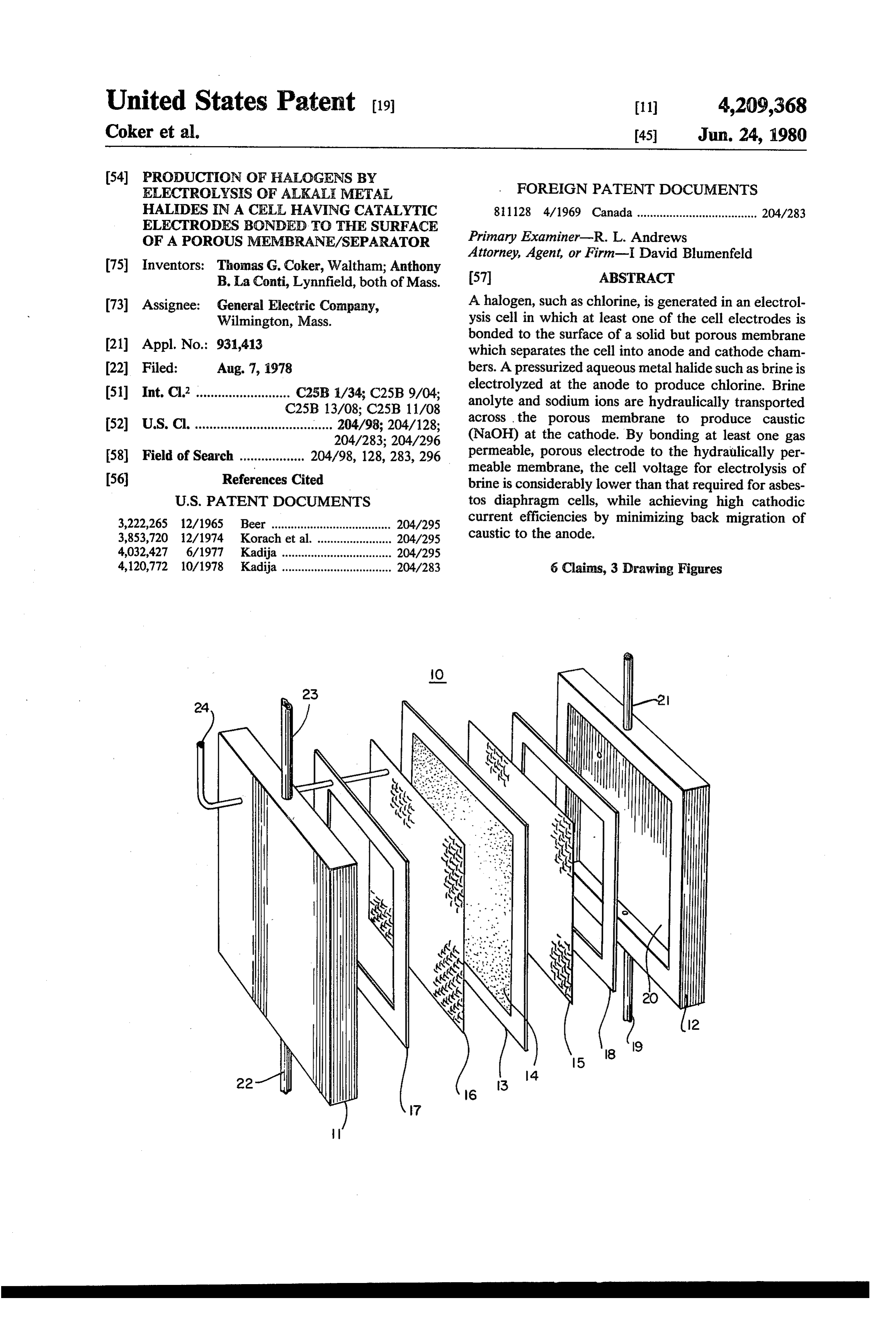
B. La Conti, Lynnfield, both of Mass. 57 ABSTRACT 73. A : General Electric Compa A halogen,9 such as chlorine,s is generated in an electrol 73 Assignee into Stomp ly, ysis cell in which at least one of the cell electrodes is bonded to the surface of a solid but porous membrane 21 Appl. No.: 931,413 which separates the cell into anode and cathode cham (22 Filed: Aug. 7, 1978 bers. A pressurized aqueous metal halide such as brine is electrolyzed at the anode to produce chlorine. Brine 51) Int. Cl. .......................... i 7.i 5. pY. anolyte and sodium ions are hydraulically transported 52 U.S. Cl C251 2.4/98.204A. across the porous membrane to produce caustic have VWia as as a son as see 8 see see on so on a sasse a 204/283. 204/296 (NaOH) at the cathode. By bonding at least one gas
permeable, porous electrode to the hydraulically per meable membrane, the cell voltage for electrolysis of (56) References Cited brine is considerably lower than that required for asbes
3,222,265 12/1965 Beer .................. - 204/295 current efficiencies by minimizing back migration of 3,853,720 12/1974 Korach et al. ... 276 caustic to the anode.
4,032,427 6/1977 Kadija........... ... 204/295 4,120,772 10/1978 Kadija .................................. 204/283 6 Claims, 3 Drawing Figures
Page 2
Drawing sheet — no readable text.
Page 3
Drawing sheet — no readable text.
Page 4
In accordance with the invention, halogens, i.e., chlo
PRODUCTION OF HALOGENS BY rine, bromine, etc., are generated by electrolyzing an ELECTROLYSIS OF ALKALIMETALHALDESIN aqueous alkali metal halide, such as NaCl, etc., in a cell A CELL HAVING CATALYTICELECTRODES which includes a discontinuous, hydraulically permea BONDED TO THE SURFACE OF A POROUS 5 ble membrane having at least one porous, gas permeable MEMBRANE/SEPARATOR catalytic electrode bonded to the surface of the mem brane. The discontinuities in the membrane take the
This invention relates to a process and apparatus for form of randomly interconnected micro pores which producing halogens and alkali metal hydroxides by extend through the membrane. Pressurized anolyte is electrolysis of aqueous alkali metal halides. More specif. 10 brought into the cell anode chamber and the pressurized ically, the invention relates to a process and apparatus anolyte passes through the porous anode to the mem for producing chlorine and sodium hydroxide by elec brane. The anolyte and sodium ions are hydraulically trolysis of brine in a cell utilizing a porous, hydrauli transported across the membrane to form NaOH at the cally permeable membrane having at least one catalytic cathode. The pressurized anolyte sweeps NaOH away electrode bonded to the surface of the porous mem 15 from the cathode, thereby minimizing back migration of brane. sodium hydroxide to the anode. It is well known to generate halogens such as chlo The thin, porous, gas permeable catalytic electrode is rine by electrolysis of aqueous alkali metal chlorides bonded at least to one surface of the membrane at a such as sodium chloride in a cell in which the electrodes plurality of points. By bonding the electrodes to the are separated by a hydraulically permeable diaphragm 20 membrane, "electrolyte IR' drop between the elec or separator which permits passage of the sodium chlo trode and the membrane is minimized, as is gas mass ride anolyte from the anode to the cathode. Such hy transport loss due to the formation of gaseous layers draulically permeable diaphragms are typically fabri between the electrodes and the membrane. As a result, cated of asbestos fibers and include passages through the cell voltage required for electrolysis of the halide which the anolyte and sodium ions are physically trans 25 solution is reduced substantially. In addition, by using a ported to the cathode. Electrolysis of brine in such a porous but solid membrane, operation at much higher cell produces chlorine at the anode and sodium hydrox current densities (300 ASF or more) is possible; opera ide at the cathode. Electrolysis normally is conducted tion at current densities at which gas is generated so with graphite or metallic anodes which are physically rapidly that asbestos diaphragms are subject to serious separated from the asbestos diaphragm while the cath 30 damage or destruction. In addition, the need for asbes odes are usually open mesh screens of iron, steel, stain tos (with its many undesirable environmental character less steel, nickel, or similar materials, which are also istics and its potential health hazards) is avoided. physically separated from the diaphragm. The electrodes which are bonded to the porous mem Asbestos diaphragm cells, or the like, are character branes include catalytic material comprising at least one ized by high cathode current efficiencies, fairly low 35 reduced, platinum group metal oxide which is thermally concentrations of sodium hydroxide and relatively high stabilized by heating the reduced oxides in the presence cell voltages at fairly low current densities; i.e., 3.3 volts of oxygen. Examples of useful platinum group metals at a maximum of 150 amperes per square foot. Current are platinum, palladium, iridium, rhodium, ruthenium, density in asbestos diaphragm cells is limited because and osmium. For chlorine production, the preferred the asbestos fiber diaphragm is susceptible to damage or reduced metal oxides are reduced oxides of ruthenium destruction due to rapid gas evolution at high current or iridium. Mixtures or alloys of reduced platinum density. group metal oxides have been found to be the most Applicants have found that by bonding catalytic elec stable. Thermally stabilized, reduced oxides of ruthe trodes at least to one side of a porous but non-fibrous nium containing up to 25 percent by weight of ther membrane an improved apparatus and process for elec 45 mally stabilized, reduced oxides of iridium have been trolyzing aqueous alkali metal halides is possible at found very stable and corrosion resistant. Graphite or much higher current densities and at cell operating other conductive extenders, such as ruthenized tita voltages considerably lower than those possible in as nium, etc., may be added in amounts of up to 90 percent bestos diaphragm cells. by weight. The extenders should have good conductiv It is therefore a primary objective of this invention to 50 ity with a low halogen overvoltage and should be sub produce halogens efficiently by electrolysis of alkali stantially less expensive than platinum group metals. metal halide solutions in a cell utilizing a unitary mem One or more reduced oxides of a valve metal such as brane-electrode structure in which the membrane is also titanium, tantalum, niobium, hafnium, vanadium or hydraulically permeable. tungsten may be added to stabilize the electrode against It is a further objective of this invention to provide a 55 oxygen, chlorine, and the generally harsh electrolysis method and apparatus for producing chlorine by the conditions. Reference is hereby made to application electrolysis of aqueous sodium chloride wherein the cell Ser. No. 922,316, filed July 6, 1978 (52-EE-0-299) as voltage is substantially reduced by bonding at least one signed to the General Electric Company, assignee of catalytic electrode to a porous, hydraulically permeable the present invention, for additional description of the membrane. catalytic electrode constructions most useful in electrol Still another objective of the invention is to provide a ysis cells for the electrolysis of aqueous alkali metal method and apparatus for producing chlorine by the halides.
electrolysis of aqueous sodium chloride with substan The novel features which are believed to be charac tially lower cell voltages and high current efficiency by teristic of this invention are set forth with particularity using both a porous membrane and electrodes bonded 65 in the appended claims. The invention itself, however, to the membrane. both as to its organization and method of operation, Other objectives and advantages of the invention will together with further objectives and advantages, may become apparent as the description thereof proceeds. best be understood by reference to the following de
Page 5
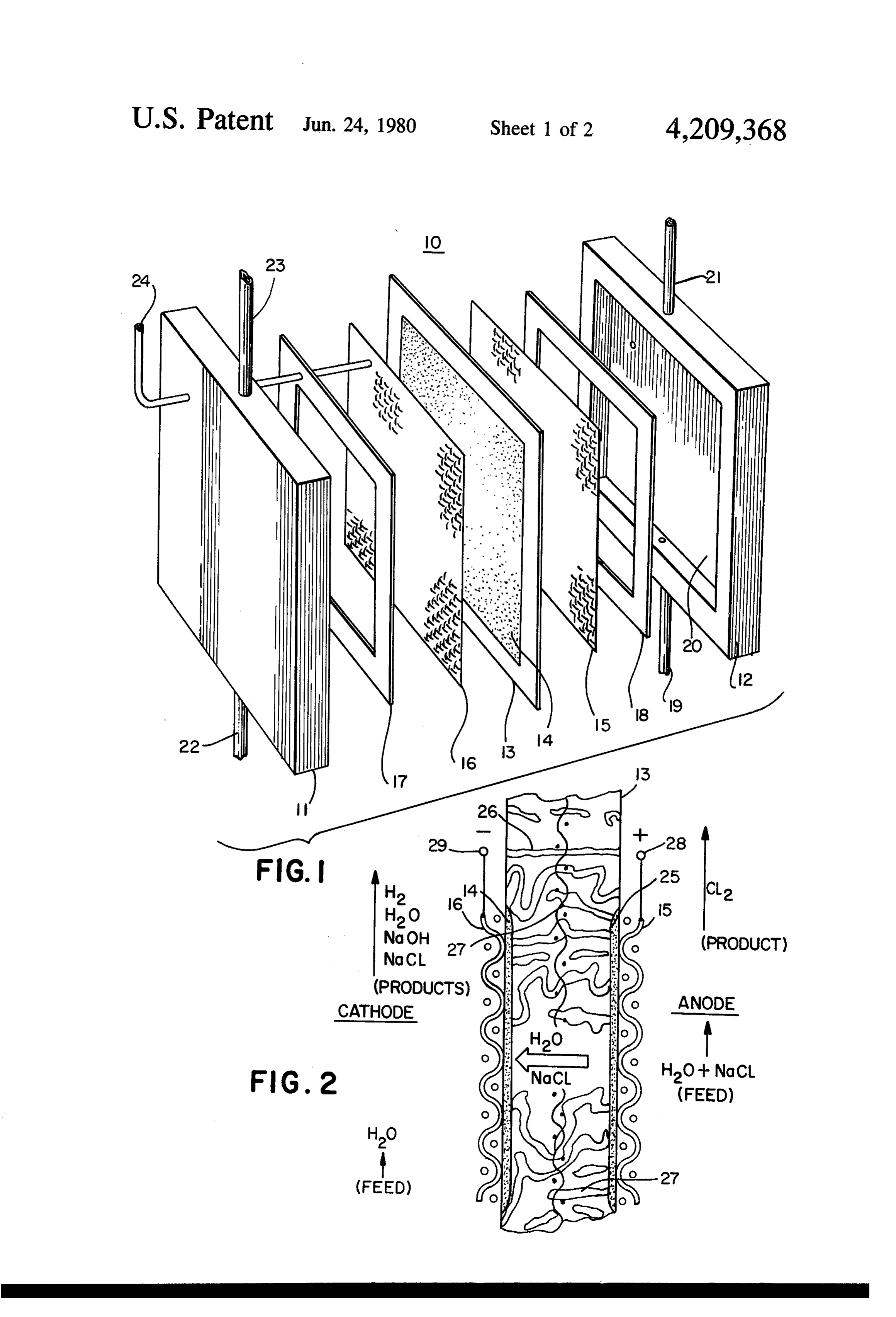
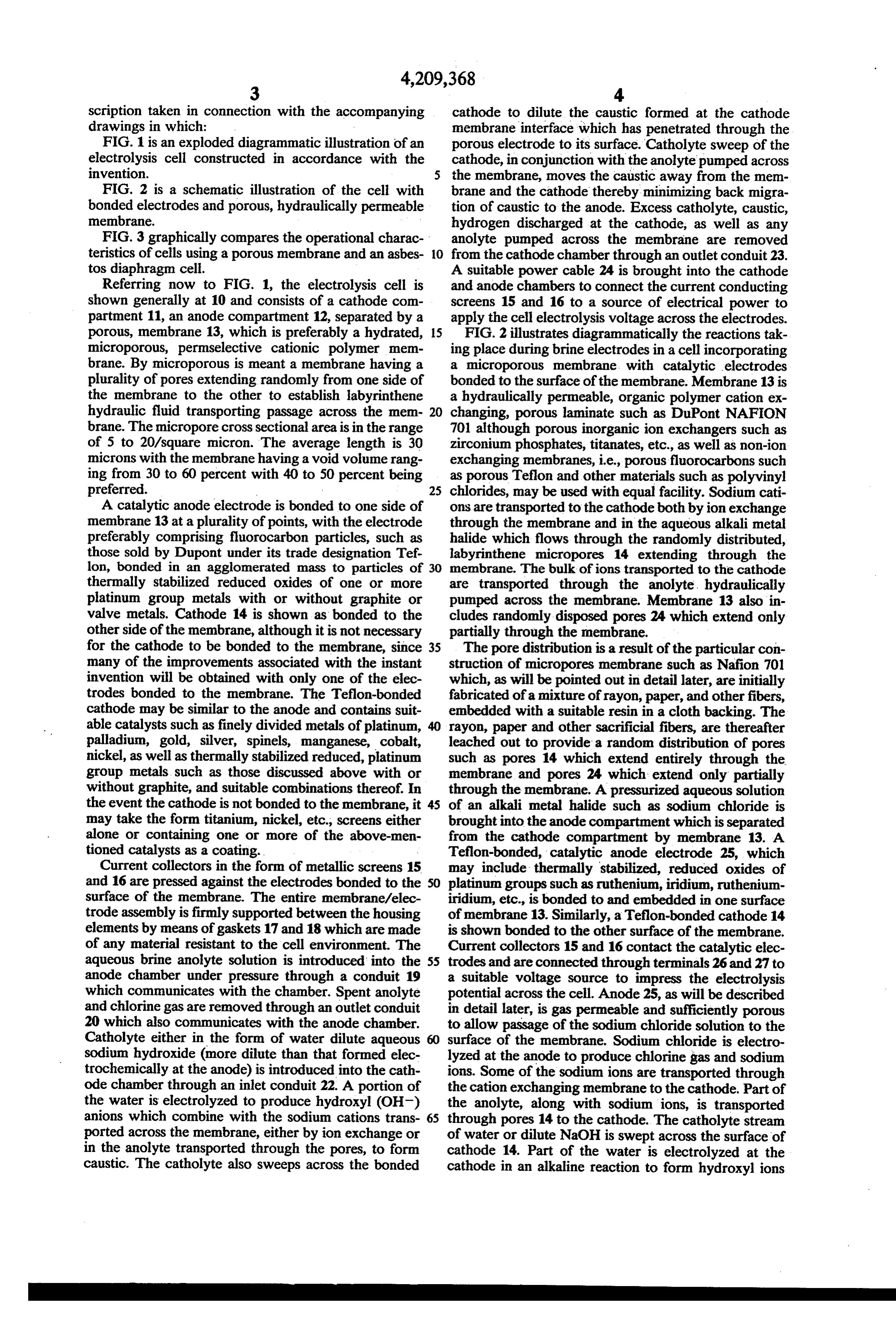
scription taken in connection with the accompanying cathode to dilute the caustic formed at the cathode drawings in which: membrane interface which has penetrated through the FIG. 1 is an exploded diagrammatic illustration of an porous electrode to its surface. Catholyte sweep of the electrolysis cell constructed in accordance with the cathode, in conjunction with the anolyte pumped across invention. 5 the membrane, moves the caustic away from the mem FIG. 2 is a schematic illustration of the cell with brane and the cathode thereby minimizing back migra bonded electrodes and porous, hydraulically permeable tion of caustic to the anode. Excess catholyte, caustic, membrane. hydrogen discharged at the cathode, as well as any FIG. 3 graphically compares the operational charac anolyte pumped across the membrane are removed teristics of cells using a porous membrane and an asbes 10 from the cathode chamber through an outlet conduit 23. tos diaphragm cell. A suitable power cable 24 is brought into the cathode Referring now to FIG. 1, the electrolysis cell is and anode chambers to connect the current conducting shown generally at 10 and consists of a cathode com screens 15 and 16 to a source of electrical power to partment 11, an anode compartment 12, separated by a apply the cell electrolysis voltage across the electrodes. porous, membrane 13, which is preferably a hydrated, 15 FIG. 2 illustrates diagrammatically the reactions tak microporous, permselective cationic polymer mem ing place during brine electrodes in a cell incorporating brane. By microporous is meant a membrane having a a microporous membrane, with catalytic electrodes plurality of pores extending randomly from one side of bonded to the surface of the membrane. Membrane 13 is the membrane to the other to establish labyrinthene a hydraulically permeable, organic polymer cation ex hydraulic fluid transporting passage across the mem- 20 changing, porous laminate such as DuPont NAFION brane. The micropore cross sectional area is in the range 701 although porous inorganic ion exchangers such as of 5 to 20/square micron. The average length is 30 zirconium phosphates, titanates, etc., as well as non-ion microns with the membrane having a void volume rang exchanging membranes, i.e., porous fluorocarbons such ing from 30 to 60 percent with 40 to 50 percent being as porous Teflon and other materials such as polyvinyl preferred. 25 chlorides, may be used with equal facility. Sodium cati A catalytic anode electrode is bonded to one side of ons are transported to the cathode both by ion exchange membrane 13 at a plurality of points, with the electrode through the membrane and in the aqueous alkali metal preferably comprising fluorocarbon particles, such as halide which flows through the randomly distributed, those sold by Dupont under its trade designation Tef labyrinthene micropores 14 extending through the lon, bonded in an agglomerated mass to particles of 30 membrane. The bulk of ions transported to the cathode thermally stabilized reduced oxides of one or more are transported through the anolyte. hydraulically platinum group metals with or without graphite or pumped across the membrane. Membrane 13 also in valve metals. Cathode 14 is shown as bonded to the cludes randomly disposed pores 24 which extend only other side of the membrane, although it is not necessary partially through the membrane. for the cathode to be bonded to the membrane, since 35 The pore distribution is a result of the particular con many of the improvements associated with the instant struction of micropores membrane such as Nafion 701 invention will be obtained with only one of the elec which, as will be pointed out in detail later, are initially trodes bonded to the membrane. The Teflon-bonded fabricated of a mixture of rayon, paper, and other fibers, cathode may be similar to the anode and contains suit embedded with a suitable resin in a cloth backing. The able catalysts such as finely divided metals of platinum, rayon, paper and other sacrificial fibers, are thereafter palladium, gold, silver, spinels, manganese, cobalt, leached out to provide a random distribution of pores nickel, as well as thermally stabilized reduced, platinum such as pores 14 which extend entirely through the group metals, such as those discussed above with or membrane and pores 24 which extend only partially without graphite, and suitable combinations thereof. In through the membrane. A pressurized aqueous solution the event the cathode is not bonded to the membrane, it 45 of an alkali metal halide such as sodium chloride is may take the form titanium, nickel, etc., screens either brought into the anode compartment which is separated alone or containing one or more of the above-men from the cathode compartment by membrane 13. A tioned catalysts as a coating. Teflon-bonded, catalytic anode electrode 25, which Current collectors in the form of metallic screens 15 may include thermally stabilized, reduced oxides of and 16 are pressed against the electrodes bonded to the SO platinum groups such as ruthenium, iridium, ruthenium surface of the membrane. The entire membrane/elec iridium, etc., is bonded to and embedded in one surface trode assembly is firmly supported between the housing of membrane 13. Similarly, a Teflon-bonded cathode 14 elements by means of gaskets 17 and 18 which are made is shown bonded to the other surface of the membrane. of any material resistant to the cell environment. The Current collectors 15 and 16 contact the catalytic elec aqueous brine anolyte solution is introduced into the 55 trodes and are connected through terminals 26 and 27 to anode chamber under pressure through a conduit 19 a suitable voltage source to impress the electrolysis which communicates with the chamber. Spent anolyte potential across the cell. Anode 25, as will be described and chlorine gas are removed through an outlet conduit in detail later, is gas permeable and sufficiently porous 20 which also communicates with the anode chamber. to allow passage of the sodium chloride solution to the Catholyte either in the form of water dilute aqueous surface of the membrane. Sodium chloride is electro sodium hydroxide (more dilute than that formed elec lyzed at the anode to produce chlorine gas and sodium trochemically at the anode) is introduced into the cathions. Some of the sodium ions are transported through ode chamber through an inlet conduit 22. A portion of the cation exchanging membrane to the cathode. Part of the water is electrolyzed to produce hydroxyl (OH) the anolyte, along with sodium ions, is transported anions which combine with the sodium cations trans- 65 through pores 14 to the cathode. The catholyte stream ported across the membrane, either by ion exchange or of water or dilute NaOH is swept across the surface of in the anolyte transported through the pores, to form cathode 14. Part of the water is electrolyzed at the caustic. The catholyte also sweeps across the bonded cathode in an alkaline reaction to form hydroxyl ions
Page 6
and gaseous hydrogen. The hydroxyl ions combine through the membrane or they may be of a winding with the sodium ions transported across the membrane labyrinthene nature.
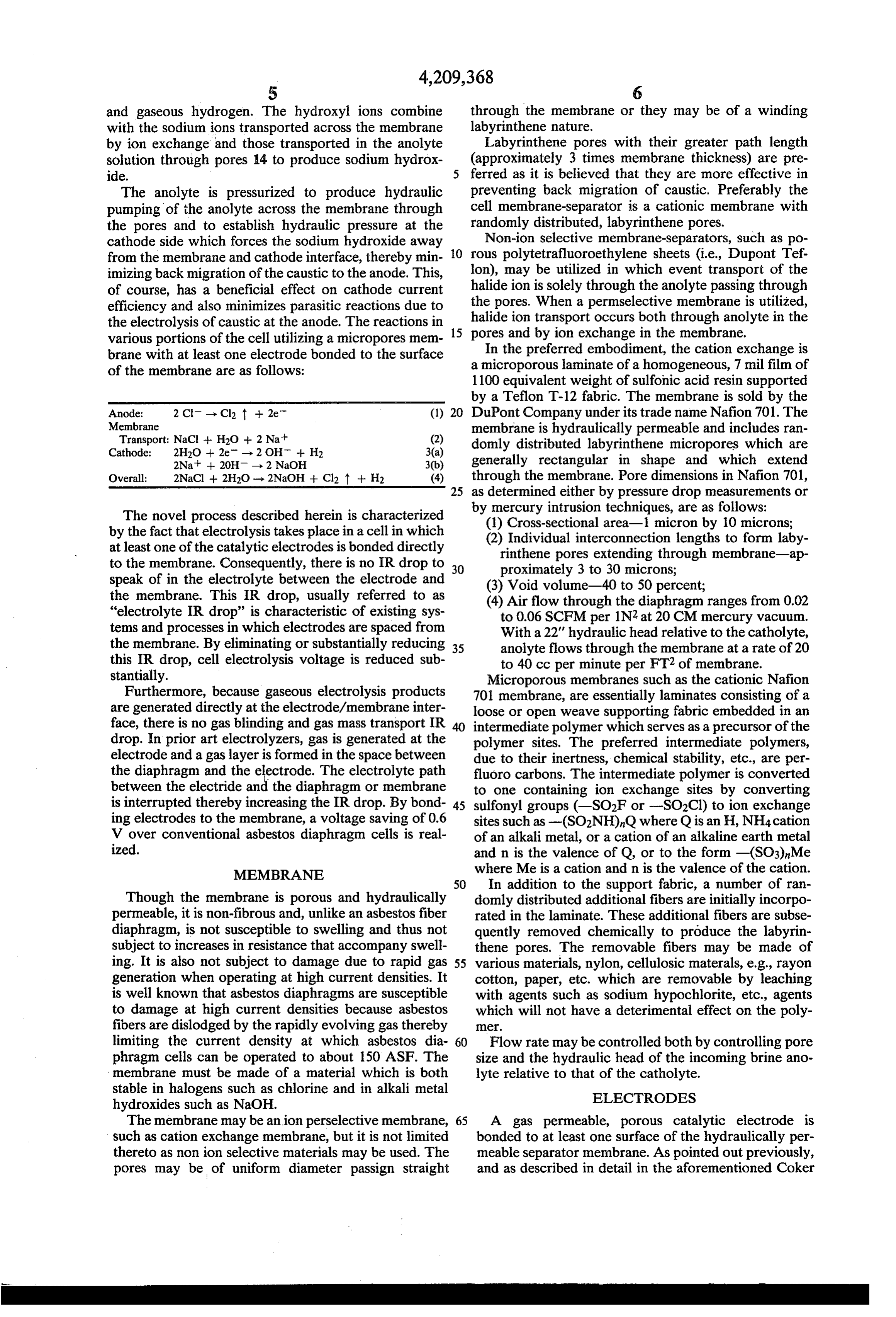
by ion exchange and those transported in the anolyte Labyrinthene pores with their greater path length solution through pores 14 to produce sodium hydrox (approximately 3 times membrane thickness) are pre ide. ferred as it is believed that they are more effective in The anolyte is pressurized to produce hydraulic preventing back migration of caustic, Preferably the pumping of the anolyte across the membrane through cell membrane-separator is a cationic membrane with the pores and to establish hydraulic pressure at the randomly distributed, labyrinthene pores. cathode side which forces the sodium hydroxide away Non-ion selective membrane-separators, such as po from the membrane and cathode interface, thereby min O rous polytetrafluoroethylene sheets (i.e., Dupont Tef. imizing back migration of the caustic to the anode. This, lon), may be utilized in which event transport of the of course, has a beneficial effect on cathode current halide ion is solely through the anolyte passing through efficiency and also minimizes parasitic reactions due to the pores. When a permselective membrane is utilized, the electrolysis of caustic at the anode. The reactions in 15 halide ion transport occurs both through anolyte in the various portions of the cell utilizing a micropores mem pores and by ion exchange in the membrane. brane with at least one electrode bonded to the surface In the preferred embodiment, the cation exchange is of the membrane are as follows: a microporous laminate of a homogeneous, 7 mil film of 1100 equivalent weight of sulfonic acid resin supported by a Teflon T-12 fabric. The membrane is sold by the
Anode: 2 Cl - Cl2 t +2e. (1) 20 DuPont Company under its trade name Nafion 701. The Membrane membrane is hydraulically permeable and includes ran Transport: NaCl + H2O + 2 Nat (2) domly distributed labyrinthene micropores which are Cathode: 2H2O -- 2e - 2 OH + H2 3(a) 2Na -- 20H - 2 NaOH 3(b) generally rectangular in shape and which extend Overall: 2NaCl + 2H2O - 2NaOH + Cl2 t + H2 (4) through the membrane. Pore dimensions in Nafion 701, 25 as determined either by pressure drop measurements or
The novel process described herein is characterized by(1) mercury intrusion techniques, are as follows: Cross-sectional area-1 micron by 10 microns;
by the fact that electrolysis takes place in a cell in which (2) Individual interconnection lengths to form laby at least one of the catalytic electrodes is bonded directly rinthene pores extending through membrane-ap to the membrane. Consequently, there is no IR drop to 30 proximately 3 to 30 microns; speak of in the electrolyte between the electrode and (3) Void volume-40 to 50 percent; the membrane. This IR drop, usually referred to as (4) Air flow through the diaphragm ranges from 0.02 "electrolyte IR drop' is characteristic of existing sys to 0.06 SCFM per 1N2 at 20 CM mercury vacuum. tems and processes in which electrodes are spaced from With a 22' hydraulic head relative to the catholyte, the membrane. By eliminating or substantially reducing 35 anolyte flows through the membrane at a rate of 20 this IR drop, cell electrolysis voltage is reduced sub to 40 cc per minute per FT2 of membrane. stantially. Microporous membranes such as the cationic Nafion Furthermore, because gaseous electrolysis products 701 membrane, are essentially laminates consisting of a are generated directly at the electrode/membrane inter loose or open weave supporting fabric embedded in an face, there is no gas blinding and gas mass transport IR intermediate polymer which serves as a precursor of the drop. In prior art electrolyzers, gas is generated at the polymer sites. The preferred intermediate polymers, electrode and a gas layer is formed in the space between due to their inertness, chemical stability, etc., are per the diaphragm and the electrode. The electrolyte path fluoro carbons. The intermediate polymer is converted between the electride and the diaphragm or membrane to one containing ion exchange sites by converting is interrupted thereby increasing the IR drop. By bond 45 sulfonyl groups (-SO2F or -SO2Cl) to ion exchange ing electrodes to the membrane, a voltage saving of 0.6 sites such as -(SO2NH),Q where Q is an H, NH4 cation V over conventional asbestos diaphragm cells is real of an alkali metal, or a cation of an alkaline earth metal ized. and n is the valence of Q, or to the form -(SO3)Me MEMBRANE where Me is a cation and n is the valence of the cation. 50 In addition to the support fabric, a number of ran
Though the membrane is porous and hydraulically domly distributed additional fibers are initially incorpo permeable, it is non-fibrous and, unlike an asbestos fiber rated in the laminate. These additional fibers are subse diaphragm, is not susceptible to swelling and thus not quently removed chemically to produce the labyrin subject to increases in resistance that accompany swell thene pores. The removable fibers may be made of ing. It is also not subject to damage due to rapid gas 55 various materials, nylon, cellulosic materals, e.g., rayon generation when operating at high current densities. It cotton, paper, etc. which are removable by leaching is well known that asbestos diaphragms are susceptible with agents such as sodium hypochlorite, etc., agents to damage at high current densities because asbestos which will not have a deterimental effect on the poly fibers are dislodged by the rapidly evolving gas thereby e limiting the current density at which asbestos dia 60 Flow rate may be controlled both by controlling pore phragm cells can be operated to about 150 ASF. The size and the hydraulic head of the incoming brine ano membrane must be made of a material which is both lyte relative to that of the catholyte. stable in halogens such as chlorine and in alkali metal ELECTRODES hydroxides such as NaOH.
The membrane may be anion perselective membrane, 65 A gas permeable, porous catalytic electrode is such as cation exchange membrane, but it is not limited bonded to at least one surface of the hydraulically per thereto as non ion selective materials may be used. The meable separator membrane. As pointed out previously, pores may be of uniform diameter passign straight and as described in detail in the aforementioned Coker
Page 7
application, Ser. No. 922,316, the bonded anode prefer Similarly, if the cathode is bonded to the membrane, it ably includes reduced oxides of platinum group metals has to be porous to allow penetration of the sweep such as ruthenium, iridium, etc. The reduced platinum water to the electrode/membrane interface to aid in metal group oxides are stabilized against chlorine and diluting the NaOH formed at the membrane electrode oxygen evolution to minimize corrosion. Stabilization is 5 interface. In order to maximize penetration of the aque effected by temperature (thermal) stabilization; i.e., by ous feed stock to the electrode, the Teflon content of heating the reduced oxides of the platinum group metal, the anode electrode should not exceed 15 percent to 50 at a temperture below that at which the reduced oxides percent by weight, as Teflon is hydrophobic. By limit begin to be decomposed to pure metal. Thus, the re ing the Teflon content, and by providing a very thin, duced oxides are heated from thirty (30) minutes to six O open electrode structure, good porosity is achieved to (6) hours at 350-750° C. with the preferable stabiliza permit ready transport of the aqueous solutions through tion procedure involving heaving for one (1) hour in the the electrode to the membrane and hence to the pores temperature range of 550 to 600 C. The reduced ox extending from opposite sides of the membrane to per ides of ruthenium, may include reduced oxides of other mit hydraulic transport of anolyte to the cathode. platinum group metals, such as iridium, or also with 15 The current collector for the cathode must be care reduced oxides of valve metals, such as titanium, tanta fully selected since the highly corrosive caustic present lum, and with other extenders such as graphite, nio at the cathode attacks many materials, especially during bium, zirconium, hafnium, etc. shutdown of the cell. The current collector may take The cathode is preferably a bonded mixture of Teflon the form of a nickel screen, since nickel is resistant to particles and platinum black with a loading of 0.04 to 4 caustic. Alternatively, the current collector may be milligrams cm2. constructed of a stainless steel plate with a stainless steel The alloys of the reduced platinum group metal ox screen welded to the plate. Another cathode current ides along with reduced oxides of titanium and other structure which is resistant to or inert in the caustic transition metals are blended with Teflon to form a solution is graphite, or graphite in combination with a homogeneous mix. Metal loading, for the anode may be 25 nickel screen, pressed to the plate and against the sur as low as 0.6 milligrams/cm2 with the preferred range face of the electrode.
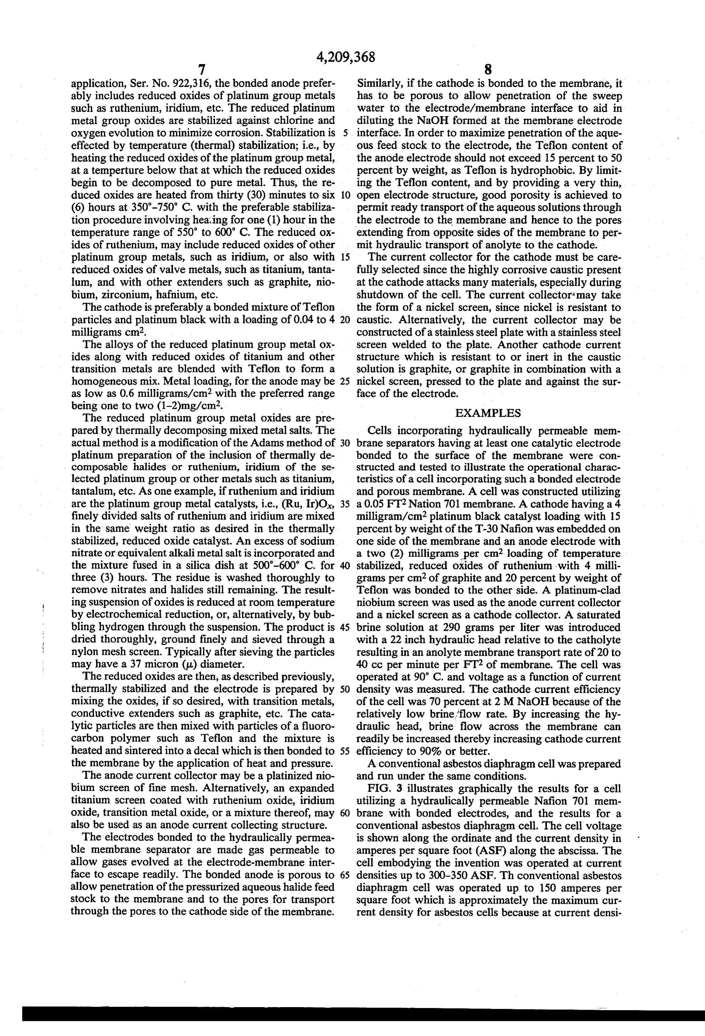
being one to two (1-2)mg/cm2. EXAMPLES The reduced platinum group metal oxides are pre pared by thermally decomposing mixed metal salts. The Cells incorporating hydraulically permeable mem actual method is a modification of the Adams method of 30 brane separators having at least one catalytic electrode platinum preparation of the inclusion of thermally de bonded to the surface of the membrane were con composable halides or ruthenium, iridium of the se structed and tested to illustrate the operational charac lected platinum group or other metals such as titanium, teristics of a cell incorporating such a bonded electrode tantalum, etc. As one example, if ruthenium and iridium and porous membrane. A cell was constructed utilizing are the platinum group metal catalysts, i.e., (Ru, Ir)O, 35 a 0.05 FT2 Nation 701 membrane. A cathode having a 4 finely divided salts of ruthenium and iridium are mixed milligram/cm2 platinum black catalyst loading with 15 in the same weight ratio as desired in the thermally percent by weight of the T-30 Nafion was embedded on stabilized, reduced oxide catalyst. An excess of sodium one side of the membrane and an anode electrode with nitrate or equivalent alkali metal salt is incorporated and a two (2) milligrams per cm loading of temperature the mixture fused in a silica dish at 500-600 C. for 40 stabilized, reduced oxides of ruthenium with 4 milli three (3) hours. The residue is washed thoroughly to grams per cm2 of graphite and 20 percent by weight of remove nitrates and halides still remaining. The result Teflon was bonded to the other side. A platinum-clad ing suspension of oxides is reduced at room temperature niobium screen was used as the anode current collector by electrochemical reduction, or, alternatively, by bub and a nickel screen as a cathode collector. A saturated bling hydrogen through the suspension. The product is 45 brine solution at 290 grams per liter was introduced dried thoroughly, ground finely and sieved through a with a 22 inch hydraulic head relative to the catholyte nylon mesh screen. Typically after sieving the particles resulting in an anolyte membrane transport rate of 20 to may have a 37 micron (u) diameter. 40 cc per minute per FT2 of membrane. The cell was The reduced oxides are then, as described previously, operated at 90° C. and voltage as a function of current thermally stabilized and the electrode is prepared by 50 density was measured. The cathode current efficiency mixing the oxides, if so desired, with transition metals, of the cell was 70 percent at 2 MNaOH because of the conductive extenders such as graphite, etc. The cata relatively low brine flow rate. By increasing the hy lytic particles are then mixed with particles of a fluoro draulic head, brine flow across the membrane can carbon polymer such as Teflon and the mixture is readily be increased thereby increasing cathode current heated and sintered into a decal which is then bonded to 55 efficiency to 90% or better. the membrane by the application of heat and pressure. A conventional asbestos diaphragm cell was prepared The anode current collector may be a platinized nio and run under the same conditions.
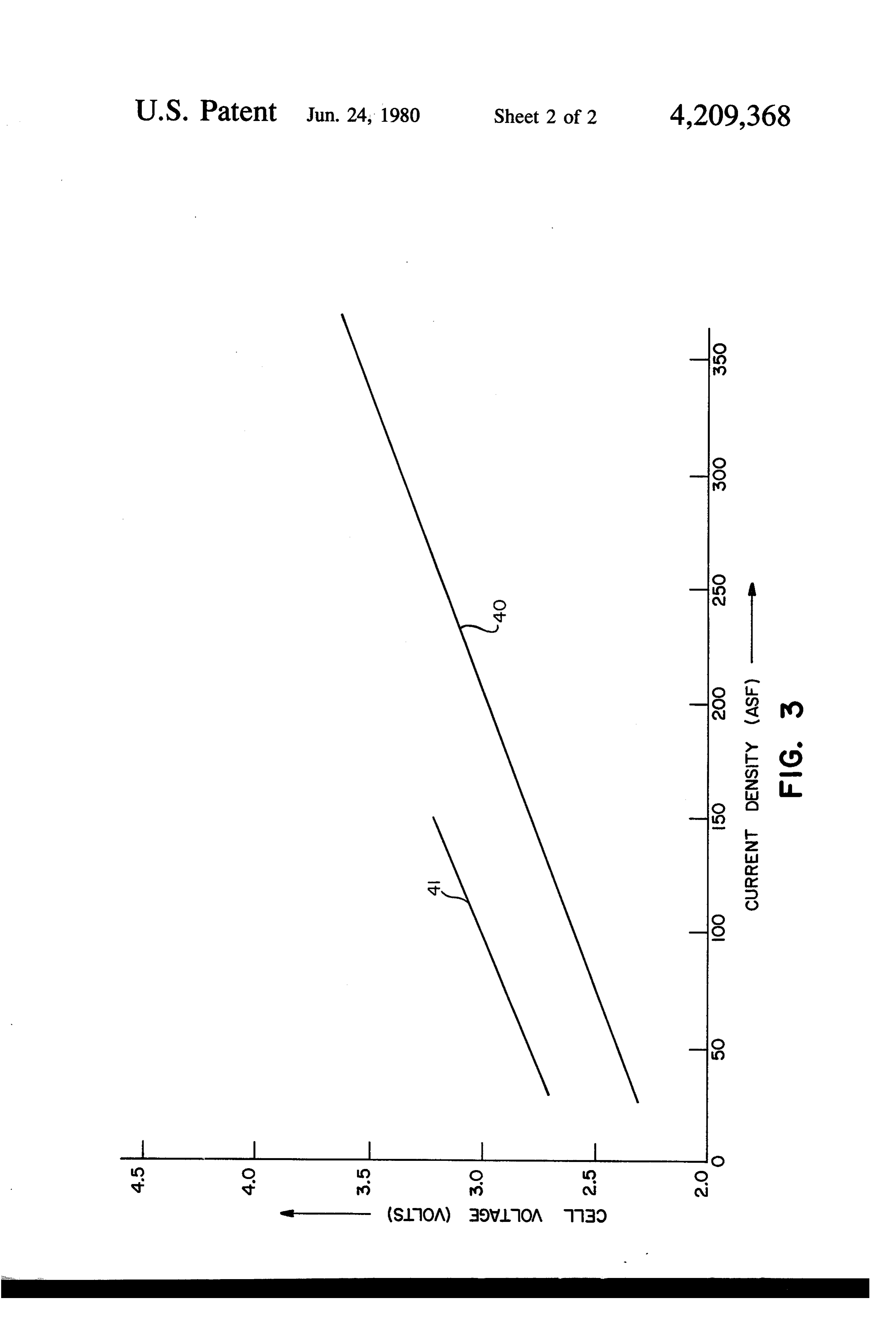
bium screen of fine mesh. Alternatively, an expanded FIG. 3 illustrates graphically the results for a cell titanium screen coated with ruthenium oxide, iridium utilizing a hydraulically permeable Nafion 701 mem oxide, transition metal oxide, or a mixture thereof, may brane with bonded electrodes, and the results for a also be used as an anode current collecting structure. conventional asbestos diaphragm cell. The cell voltage The electrodes bonded to the hydraulically permea is shown along the ordinate and the current density in ble membrane separator are made gas permeable to amperes per square foot (ASF) along the abscissa. The allow gases evolved at the electrode-membrane inter cell embodying the invention was operated at current face to escape readily. The bonded anode is porous to 65 densities up to 300-350 ASF. Th conventional asbestos allow penetration of the pressurized aqueous halide feed diaphragm cell was operated up to 150 amperes per stock to the membrane and to the pores for transport square foot which is approximately the maximum cur through the pores to the cathode side of the membrane. rent density for asbestos cells because at current densi
Page 8
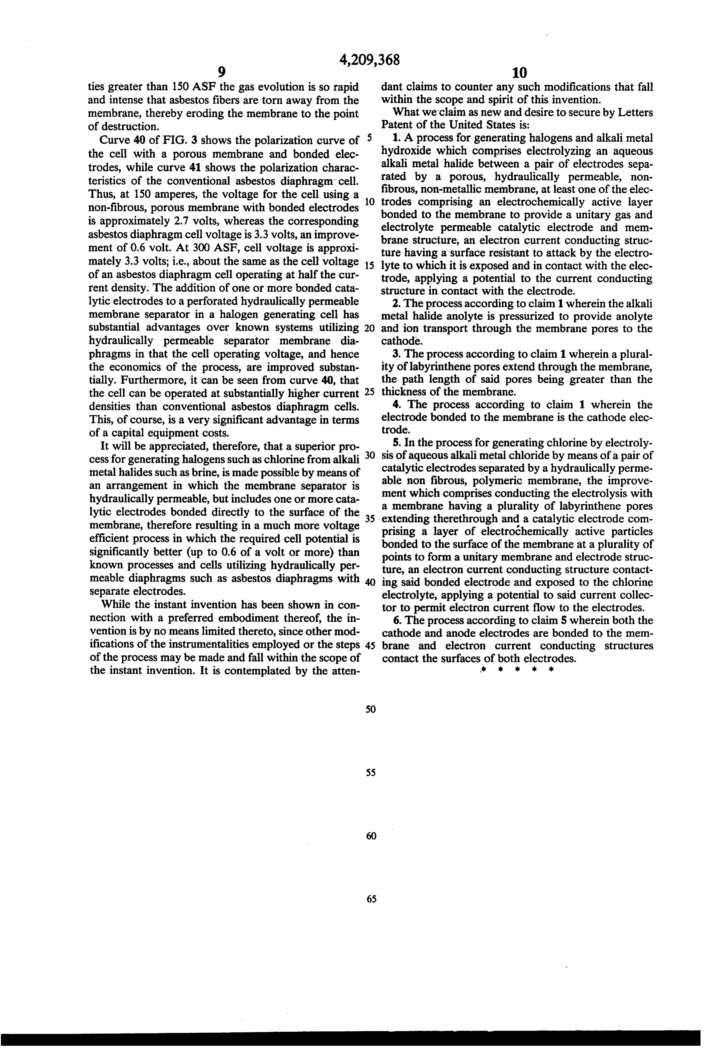
ties greater than 150 ASF the gas evolution is so rapid dant claims to counter any such modifications that fall and intense that asbestos fibers are torn away from the within the scope and spirit of this invention. membrane, thereby eroding the membrane to the point What we’claim as new and desire to secure by Letters of destruction. Patent of the United States is: Curve 40 of FIG. 3 shows the polarization curve of 1. A process for generating halogens and alkali metal the cell with a porous membrane and bonded elec hydroxide which comprises electrolyzing an aqueous alkali metal halide between a pair of electrodes sepa trodes, while curve 41 shows the polarization charac rated by a porous, hydraulically permeable, non teristics of the conventional asbestos diaphragm cell. fibrous, non-metallic membrane, at least one of the elec Thus, at 150 amperes, the voltage for the cell using a 10 trodes comprising an electrochemically active layer non-fibrous, porous membrane with bonded electrodes is approximately 2.7 volts, whereas the corresponding bonded to the membrane to provide a unitary gas and electrolyte permeable catalytic electrode and mem asbestos diaphragm cell voltage is 3.3 volts, an improve brane structure, an electron current conducting struc ment of 0.6 volt. At 300 ASF, cell voltage is approxi ture having a surface resistant to attack by the electro mately 3.3 volts; i.e., about the same as the cell voltage 15 lyte to which it is exposed and in contact with the elec of an asbestos diaphragm cell operating at half the cur trode, applying a potential to the current conducting rent density. The addition of one or more bonded cata structure in contact with the electrode. lytic electrodes to a perforated hydraulically permeable 2. The process according to claim 1 wherein the alkali membrane separator in a halogen generating cell has metal halide anolyte is pressurized to provide anolyte substantial advantages over known systems utilizing 20 and ion transport through the membrane pores to the hydraulically permeable separator membrane dia cathode.
phragms in that the cell operating voltage, and hence 3. The process according to claim 1 wherein a plural the economics of the process, are improved substan ity of labyrinthene pores extend through the membrane, tially. Furthermore, it can be seen from curve 40, that the path length of said pores being greater than the the cell can be operated at substantially higher current 25 thickness of the membrane.
densities than conventional asbestos diaphragm cells. 4. The process according to claim 1 wherein the This, of course, is a very significant advantage in terms electrode bonded to the membrane is the cathode elec of a capital equipment costs. trode.
It will be appreciated, therefore, that a superior pro 30 5. In the process for generating chlorine by electroly cess for generating halogens such as chlorine from alkali sis of aqueous alkali metal chloride by means of a pair of metal halides such as brine, is made possible by means of able non electrodes catalytic separated by a hydraulically perme fibrous, polymeric membrane, the improve an arrangement in which the membrane separator is ment which hydraulically permeable, but includes one or more cata a membranecomprises conducting the electrolysis with lytic electrodes bonded directly to the surface of the 35 extending therethroughplurality having a and a of labyrinthene pores catalytic electrode com membrane, therefore resulting in a much more voltage prising a layer of electrochemically active particles efficient process in which the required cell potential is bonded to the surface of the membrane at a plurality of significantly better (up to 0.6 of a volt or more) than points to form a unitary membrane and electrode struc known processes and cells utilizing hydraulically per ture, an electron current conducting structure contact meable diaphragms such as asbestos diaphragms with ing said bonded electrode and exposed to the chlorine separate electrodes. electrolyte, applying a potential to said current collec While the instant invention has been shown in con tor to permit electron current flow to the electrodes. nection with a preferred embodiment thereof, the in 6. The process according to claim 5 wherein both the vention is by no means limited thereto, since other mod cathode and anode electrodes are bonded to the mem ifications of the instrumentalities employed or the steps 45 brane and electron current conducting structures of the process may be made and fall within the scope of contact the surfaces of both electrodes. the instant invention. It is contemplated by the atten six s Xe k
Provenance
- Collection
- Cited prior art
- Original PDF
- patentimages.storage.googleapis.com →
- Filed
- 1978-08-07
- Pages
- 8
- Method
- pdftotext (the PDF's own text layer) + pdftoppm 300dpi page scans
- Source
- Google Patents bibliographic record
- Granted
- 1980-06-24
- Inventors
- Thomas G. Coker; Anthony B. La Conti; General Electric Co
- Transcribed from
- patentimages.storage.googleapis.com →