patent · US5722157
Method of making an induction and magnetoresistance type composite magnetic head
3 March 1998
Page 1 — bibliographic record
United States Patent (19) 11 Patent Number: 5,722,157 Shouji et al. 45) Date of Patent: Mar. 3, 1998 54 METHOD OF MAKING AN INDUCTION AND 4,939,837 7/1990 Krounbi .............................. 427/130 X MAGNETORESISTANCETYPE COMPOSITE 5,045,961 9/1991 Kobayashi et al. .. ... 291603.15 X MAGNETC HEAD 5,075.956 12/1991 Das ...................................... 29/603-14 5,142,768 9/1992 Aboaf et al. ..... ... 427/131 X 5,167,062 12/1992 Castera et al. ....................... 29/603.14 75) Inventors: Shigeru Shouji; Atsushi Toyoda, both of Hamamatsu, Japan Primary Examiner-Peter Vo
Attorney, Agent, or Firm-Ostrolenk, Faber. Gerb & Soffen, (73) Assignee: Yamaha Corporation, Japan LLP
22 Filed: Jun. 25, 1996 In an induction- and MR-type composite magnetic head of the type that one of two shield films of an MR-type magnetic (30) Foreign Application Priority Data head serves as one of two cores of an induction-type Jun. 28, 1995 JP Japan . ....... 7-186320 magnetic head, conductive leads are thicker than an MR element so that steps are formed at the boundaries between (51) Int. Cl. ....................... ... G11 B 5/127 an MR element sensitive region and the conductive leads. 52 U.S. Cl. ..................................... 29/603.14; 29/603.15; An upper gap layer has a constant thickness and has a recess 29/603.16:360/113; 360/122; 427/1.31 56 on its upper surface because of topographical transfer of 58) Field of Search ........................... 29/603.12, 603.15; the underlying steps. An upper shield-lower core layer has 360/113, 119, 122, 125; 427/130, 131 a downward convex at its lower surface, because of topo graphical transfer of the recess on the upper surface of the (56) References Cited upper gap layer. However, the upper surface of the upper shield-lower core layer is flat and parallel to the MR
3,908,194 9/1975 Romankiw .......................... 360/122 X made flat and parallel to the MR element. Steps of the write 4,639.289 1/1987 Lazzari ....... 29/603.5 X gap can be removed and a record density can be increased. 4,663.685 5/1987 Tsang ...................................... 360/1.13 4,670,972 6/1987 Sakakima ............................. 29/603.13 6 Claims, 9 Drawing Sheets
Page 2
Drawing sheet — no readable text.
Page 3
Drawing sheet — no readable text.
Page 4
Drawing sheet — no readable text.
Page 5
Drawing sheet — no readable text.
Page 6
Drawing sheet — no readable text.
Page 7
Drawing sheet — no readable text.
Page 8
Drawing sheet — no readable text.
Page 9
Drawing sheet — no readable text.
Page 10
Drawing sheet — no readable text.
Page 11
METHOD OF MAKNG AN INDUCTION AND MR element 28 via the leads 30 and 31 of the MR-type MAGNETORESISTANCETYPE COMPOSITE magnetic head 12. As the head traces a track of a recording MAGNETC HEAD medium, a voltage across the MR element 28 is modulated with information recorded on the track. The modulated
BACKGROUND OF THE INVENTION 5 voltage is detected to reproduce the information. a) Field of the Invention SUMMARY OF THE INVENTION The present invention relates to induction- and It is an object of the present invention to provide an magnetoresistance(MR)-type composite magnetic heads for induction- and MR-type composite magnetic head and its hard disks or the like. O manufacture, the head being of the type that one of the shield b) Description of the Related Art films of the MR-type magnetic head serves as one of the An MR-type magnetic head is a reproduction-only mag cores of the induction-type magnetic head, and capable of netic head which detects a magnetic field established forming sharp reproduced waveforms and providing high between magnetic poles of a magnetic recording medium record density.
with an MR element and reproduces recorded information. 15 It is another object of the present invention to provide an Its advantage over an induction-type magnetic head is that induction- and MR-type composite magnetic head and its the number of tracks per inch and the number of bits per inch manufacture, capable of recording linear inverted magneti can be increased. An MR-type magnetic head for reading zation patterns.
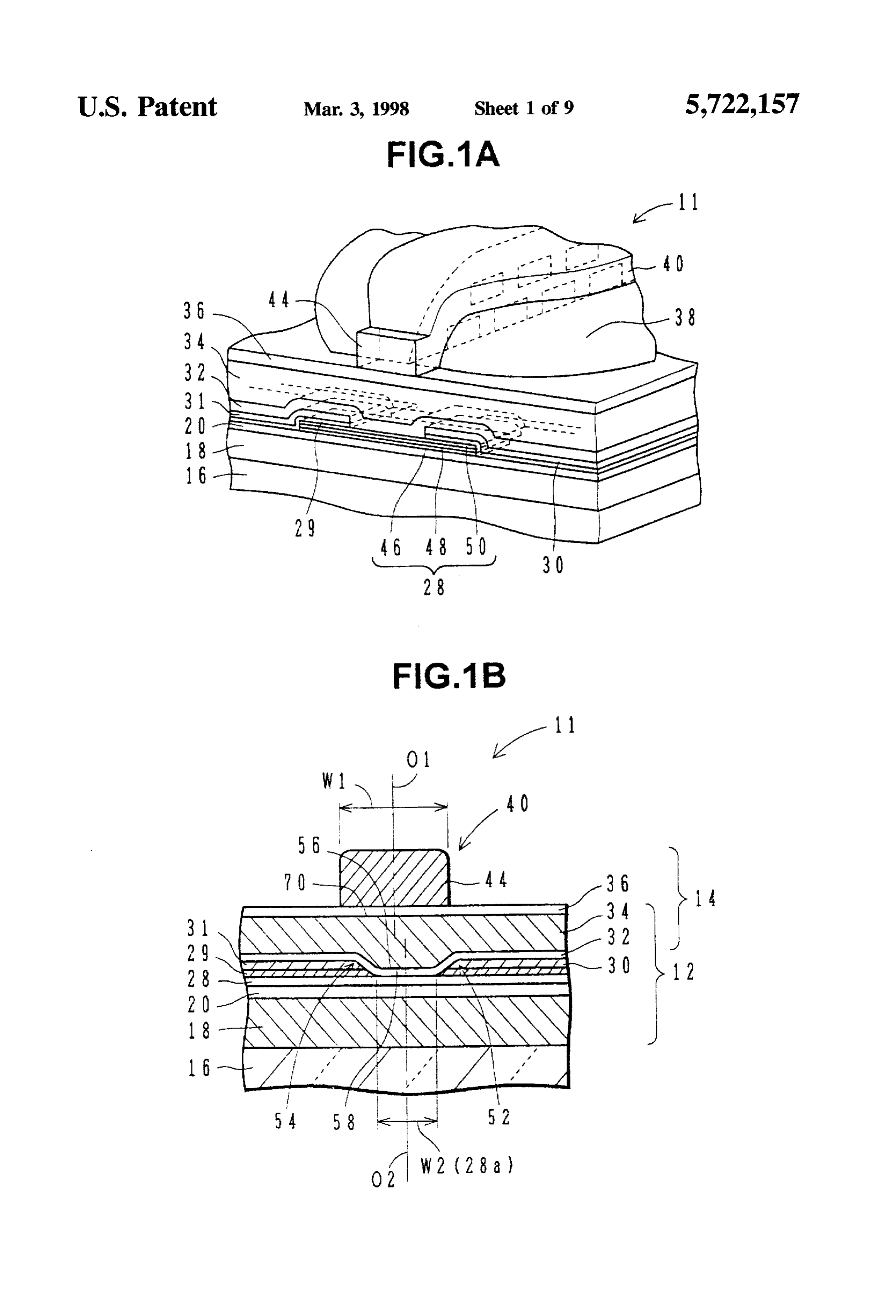
information combined with an induction-type magnetic head According to one aspect of the present invention, there is for recording information constitutes an induction- and provided a method of manufacturing an induction- and MR-type composite magnetic head. MR-type composite magnetic head comprising the steps of: A conventional induction- and MR-type composite mag forming a magnetoresistive sensor film on a flat surface of netic head for hard disk is shown in FIGS. 2A and 2B. FIG. a substrate having a slider surface generally perpendicular to 2A is a cross sectional side view, and FIG. 2B is a perspec 25 the flat surface; forming a pair of conductive lead films on tive view as seen from the recording medium facing side. In the magnetoresistive sensor film and the substrate to define FIG. 2A, the bottom surface of the composite magnetic head a sensitive region of the magnetoresistive sensor film ther is continuous with the slider surface of a substrate 16 and ebetween; forming a nonmagnetic insulating film and a first forms a magnetic read/write surface. On an MR-type mag soft magnetic layer over the substrate, the nonmagnetic netic head 12, an induction-type magnetic head 14 is stacked 30 insulating film covering the lead films and the magnetore to constitute an induction- and MR-type composite magnetic sistive sensor film, and the nonmagnetic insulating film and head 10. Both the heads 12 and 14 are formed on the back the first soft magnetic layer having upper surfaces topo end surface of the slider substrate by thin film forming graphically reflecting the lead films; lapping the surface of technology. the first soft magnetic layer to form a flat surface; and On the slider substrate 16, a lower shield layer 18 of high 35 forming a second soft magnetic layer on the flat surface of magnetic permeability of the MR-type magnetic head 12 is the first soft magnetic layer, with a write gap being inter formed. On the lower shield layer 18, a lower gap layer posed between the first and second soft magnetic layers. (reproduction gap layer) 20 made of an insulating layer is The upper surface of the first soft magnetic layer islapped laminated. On the lower gap layer 20, an MR element 28 is to remove the recess of the upper surface and make the first formed whose end surface, together with the substrate soft magnetic layer have a flat surface parallel to the surface, constitutes a recording medium facing surface (i.e. sensitive region of the MR sensor film. It is therefore ABS surface : Air Bearing Surface) 24 (FIG. 2B). The MR possible to manufacture an induction- and MR-type com element 28 is a laminate of an MR film 46, a spacer 48, and posite magnetic head having a write gap parallel to the an SAL bias film 50 (Soft Adjacent Layer : adjacent soft sensitive region of the MR sensor film. magnetic layer) stacked on the lower gap layer 20 in this 45 After the first soft magnetic layer is laminated, a sacrifi order. Lead conductors 30 and 31 are connected to right and cial film of inorganic material may be formed on the upper left sides of the MR element 28. A portion of the MR surface of the first soft magnetic layer. In this case, the element 28 which the leads 30 and 31 do not cover forms a substrate is lapped from the inorganic insulating film toward sensitive region and a portion which the leads 30 and 31 the first soft magnetic layer.
cover forms an insensitive region. On the MR element 28 50 If the sacrificial film is formed on the upper surface of the and leads 30 and 31, an upper gap layer (reproduction gap first soft magnetic layer to bury the recess on the upper layer) 32 made of an insulating film is formed, and on the surface of the first soft magnetic layer and a lapping process upper gap layer 32 an upper shield layer 34 is formed which is performed in this state, then cracks can be prevented from is made of soft magnetic material of high magnetic perme being formed in the first soft magnetic layer during the ability such as Sendust and permalloy. 55 lapping and manufacture yield can be improved. The upper shield layer 34 also serves as the lower core Since the upper surface of the first soft magnetic layer has layer of the induction-type magnetic head 14. On the upper a flat surface parallel to the sensitive region, the write gap shield layer 34. a write gap layer 36, a coil and insulating formed thereon becomes also parallel to the sensitive region. layer 38, an upper core layer 40, and a protective layer 42 are Therefore, with this write gap, inverted magnetization pat sequentially laminated. terns of a signal formed on a recording medium become In recording by the use of the induction- and MR-type linear. The waveform of a recorded signal read with the composite magnetic head 10 shown in FIGS. 2A and 2B, a linear MR sensor film becomes sharp, and a change in record signal flows through the coil of the induction-type signals recorded in a narrow area becomes clear. magnetic head 14 to generate a recording magnetic field in Accordingly, a peak of a read waveform of a single bit can the write gap layer 36 between the upper and lower core 65 be detected finely with respect to the time axis. Since a layers 40 and 34 and record information with this magnetic number of inverted magnetization patterns can be recorded field. In reproducing, a sense current is flowed through the in a narrow area of a recording medium, a record density can
Page 12
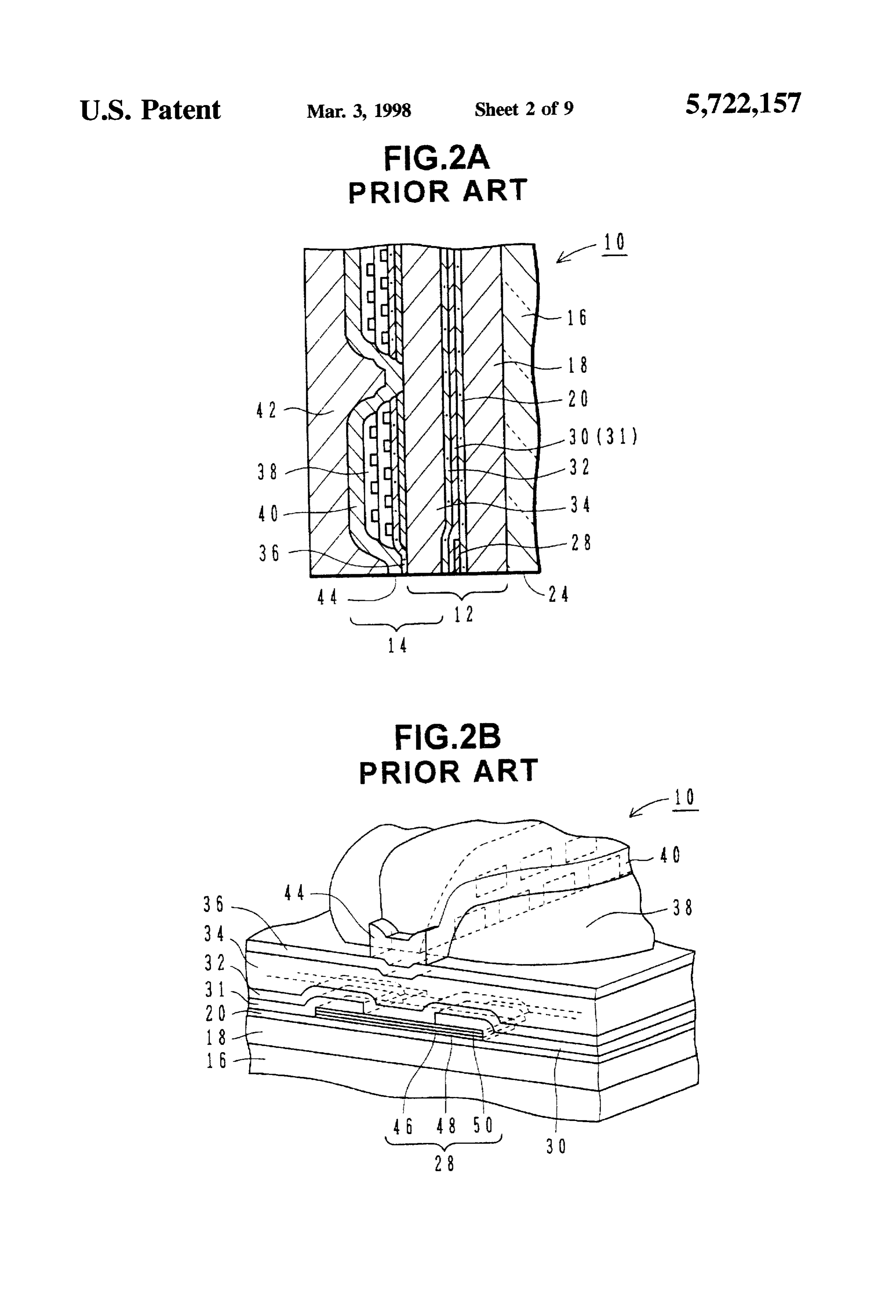
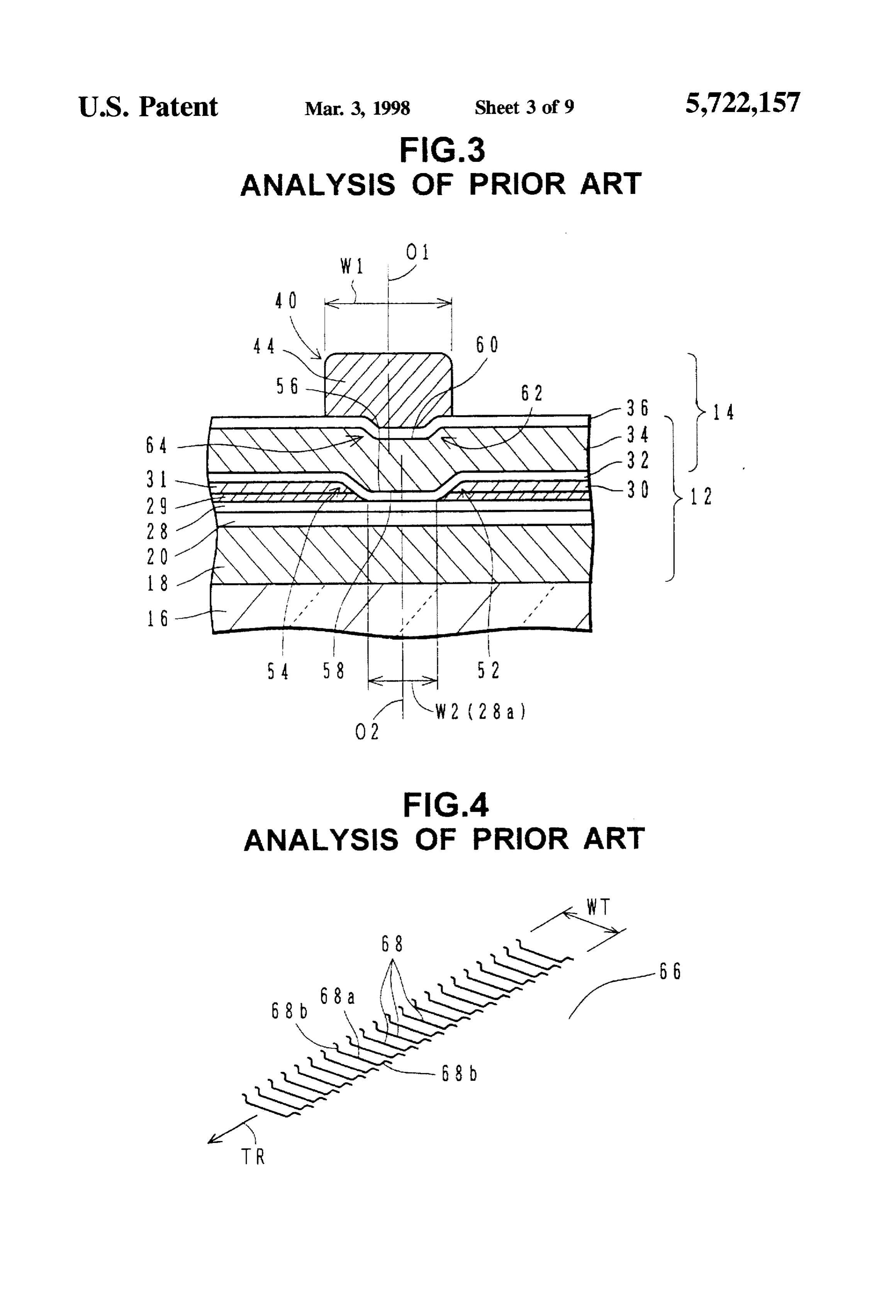
be increased. Furthermore, the nonmagnetic insulating layer FIG. 3 is a front view of the induction- and MR-type can be made thin and a predetermined narrow reproduction composite magnetic head 10 shown in FIGS. 2A and 2B as gap can be formed, because the nonmagnetic insulating seen from the air bearing surface 24 side. Lead films 30 and layer has the recess at its upper surface at the position of the 31 thicker than the MR element 28 and having a low sensitive region of the MR sensor film, the recess being resistance are formed on the left and right side areas of the formed by topographic transfer of the steps formed at the MR element 28, through a pair of longitudinal magnetic bias boundaries between the sensitive region of the MR sensor films 29. A portion of the MR element 28 between the leads and the leads. If the upper surface of the nonmagnetic 30 and 31 forms a sensitive region 28a. Generally, a write insulating layer is made flat, the nonmagnetic insulating width (generally the width of an upper pole 44) W1 is set layer becomes thick at the position of the sensitive region of 10 wider than the width W2 of the sensitive region 28a. The the MR sensor film and the record density is lowered. center 01 of the upper pole width is offset from the center 02 As above. the write gap can be formed in parallel to the of the width of the MR element sensitive region. sensitive region of the MR sensor film. With this write gap, In the manufacture processes for the induction- and inverted magnetization patterns of a signal recorded on a MR-type composite magnetic head 10 shown in FIG.3, after recording medium become linear. The waveform of a 15 the leads 30 and 31 are formed on the MR element 28, steps recorded signal reproduced with the MR sensor film 52 and 54 are formed at the boundaries between the MR becomes sharp so that inverted magnetization patterns can element sensitive region 28a and the leads 30 and 31. When be detected reliably with respect to the time axis. an upper gap layer 32 is formed over the substrate thereafter. Furthermore. a predetermined narrow reproduction gap can a recess 56 is formed on the upper surface of the upper gap be formed and the record density can be made high, because layer32, because of topographical transfer of the underlying the nonmagnetic insulating layer has the recess at its upper steps 52 and 54. When an upper shield-lower core layer 34 surface at the position of the sensitive region of the MR is formed thereon, a downward convex 58 is formed at the sensor film, the recess being formed by topographic transfer lower surface of the layer 34, and a recess 60 is formed at of the steps formed at the boundaries between the sensitive the upper surface, because of topographical transfer of the region of the MR sensor and the leads. 25 underlying recess 56 of the upper gap layer 32. Therefore, Still further, it is possible to manufacture an induction when a write gap layer 36 is formed on the upper shield and MR-type composite magnetic head having a write gap lower core layer 34, the write gap layer 36 is formed with parallel to the sensitive region of the MR sensor film. stepped portions 62 and 64 are formed, because of topo Moreover, cracks can be prevented from being formed in graphical transfer of the recess 60 on the upper surface of the the first soft magnetic layer during the lapping and manu upper shield-lower core layer 34. These stepped portions facture yield can be improved. 62 and 64 are formed, as viewed from the pole front surface.
BRIEF DESCRIPTION OF THE DRAWINGS
inside the width of the MR element sensitive region 28a because the leads 30 and 31 are thick.
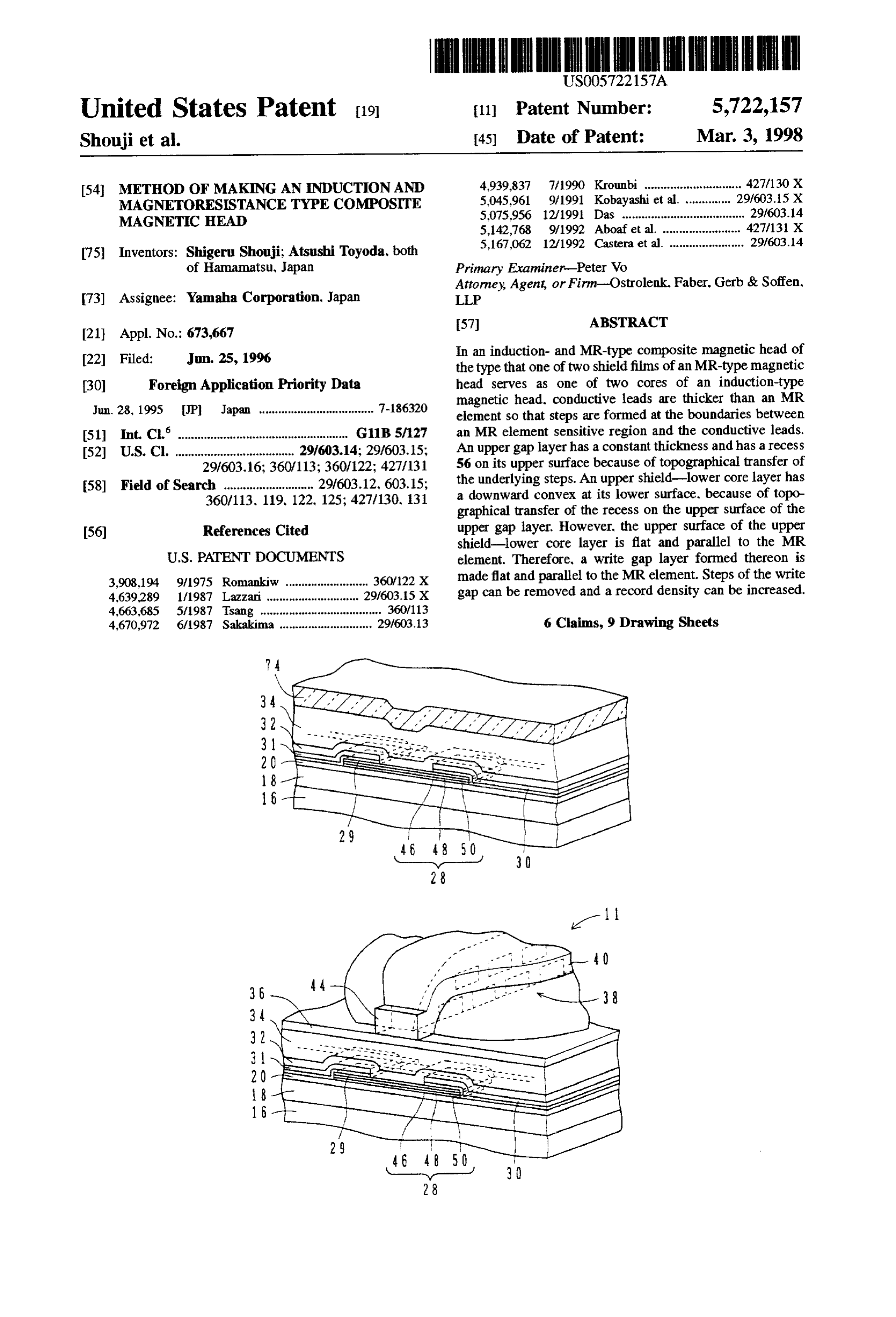
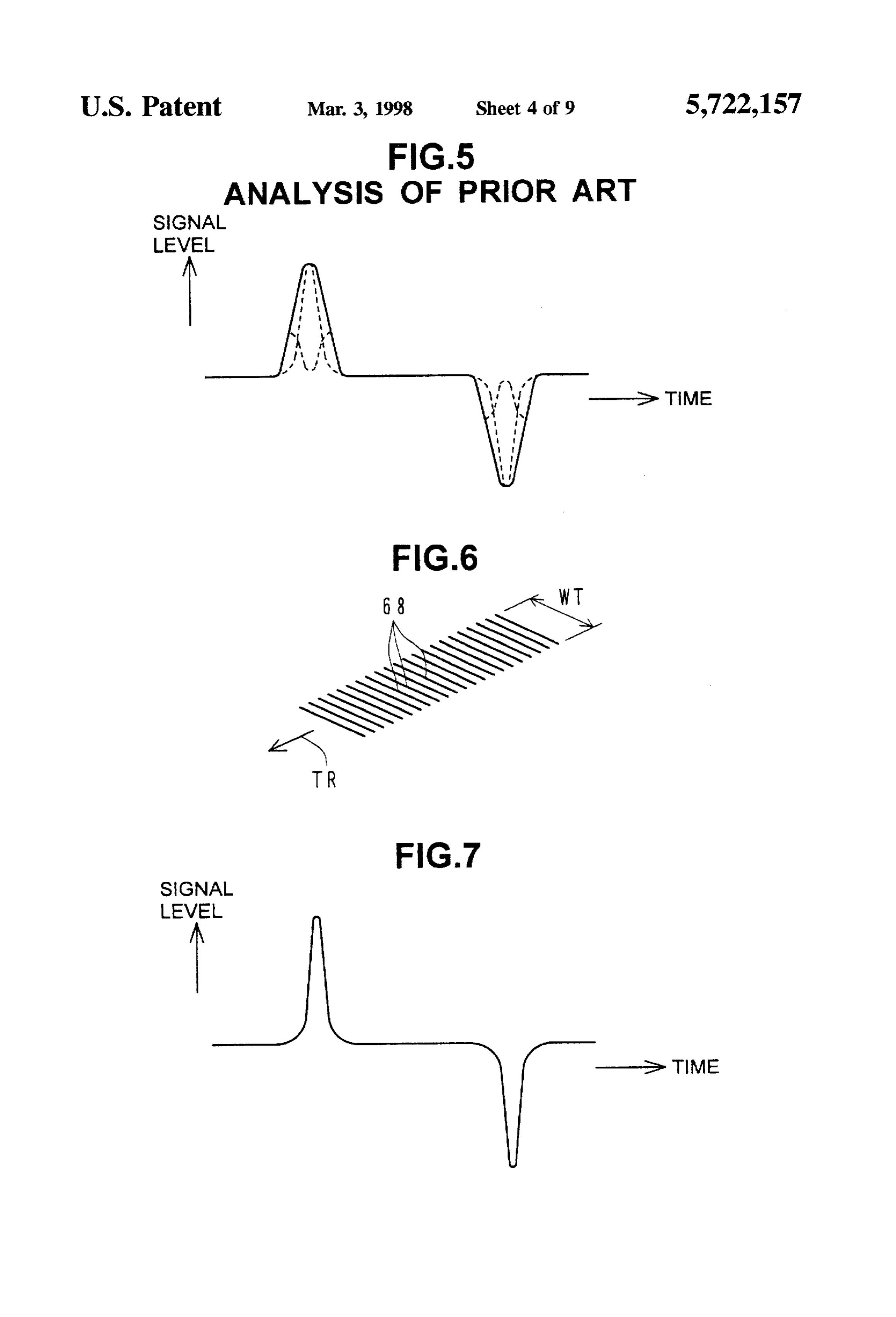
FIG. 1A is a perspective view of an induction- and FIG. 4 shows signal patterns recorded on a recording MR-type composite magnetic head as seen from the air 35 medium (hard disk) 66 with the composite magnetic head 10 bearing surface side according to an embodiment of the having the write gap 36 formed with the stepped portions 62 invention, and FIG. 1B is a front view of the composite and 64. The signal is recorded on the recording medium 66 magnetic head (bottom view of a rear portion of a slider while forming a magnetized area (inverted magnetization head). area) 68 with bent portions. Namely, the inverted magneti FIGS. 2A is a cross sectional side view of a conventional zation area 68 includes central linear and parallel magneti induction- and MR-type composite magnetic head, and FIG. zation patterns 68a and sideways bent magnetization pat 2B is a perspective view thereof as seen from the air bearing terns 68b, these patterns being distributed along a track surface side. direction TR at the write track width WT. These signal FIG. 3 is a front view of an induction- and MR-type patterns with the bent magnetization patterns 68b are read composite magnetic head seen from the air bearing surface 45 with the MR-type magnetic head 12. Since the MR element side, explaining analyses made by the present inventors. sensitive region 28a itself is linear and has no bent portions. FIG. 4 is a perspective view showing inverted magneti the reproduced signal has signal components shifted in the zation patterns of a signal recorded with a conventional time axis by the bent magnetization patterns 68b. induction-type magnetic head. A partial waveform of the reproduced signal is shown in FIG. 5 shows a signal waveform of record patterns 50 FIG. 5. The waveform of the reproduced signal is a com reproduced with a conventional MR-type magnetic head. posite of: a sharp waveform of a signal read from the parallel FIG. 6 is a perspective view showing inverted magneti magnetization patterns 68a at the central area of the track zation patterns of a signal recorded with an embodiment width WT, and a waveform of a signal read from the bent induction-type magnetic head shown in FIGS. 1A and 1B. magnetization patterns 68b before and after the sharp FIG. 7 shows a signal waveform of record patterns 55 waveform, portion. Such and has a low peak and a gently lowering skirt a reproduced signal results in unstable pickup reproduced with an embodiment MR-type magnetic head of the peak position and hinders a higher record density. shown in FIGS. 1A and B.
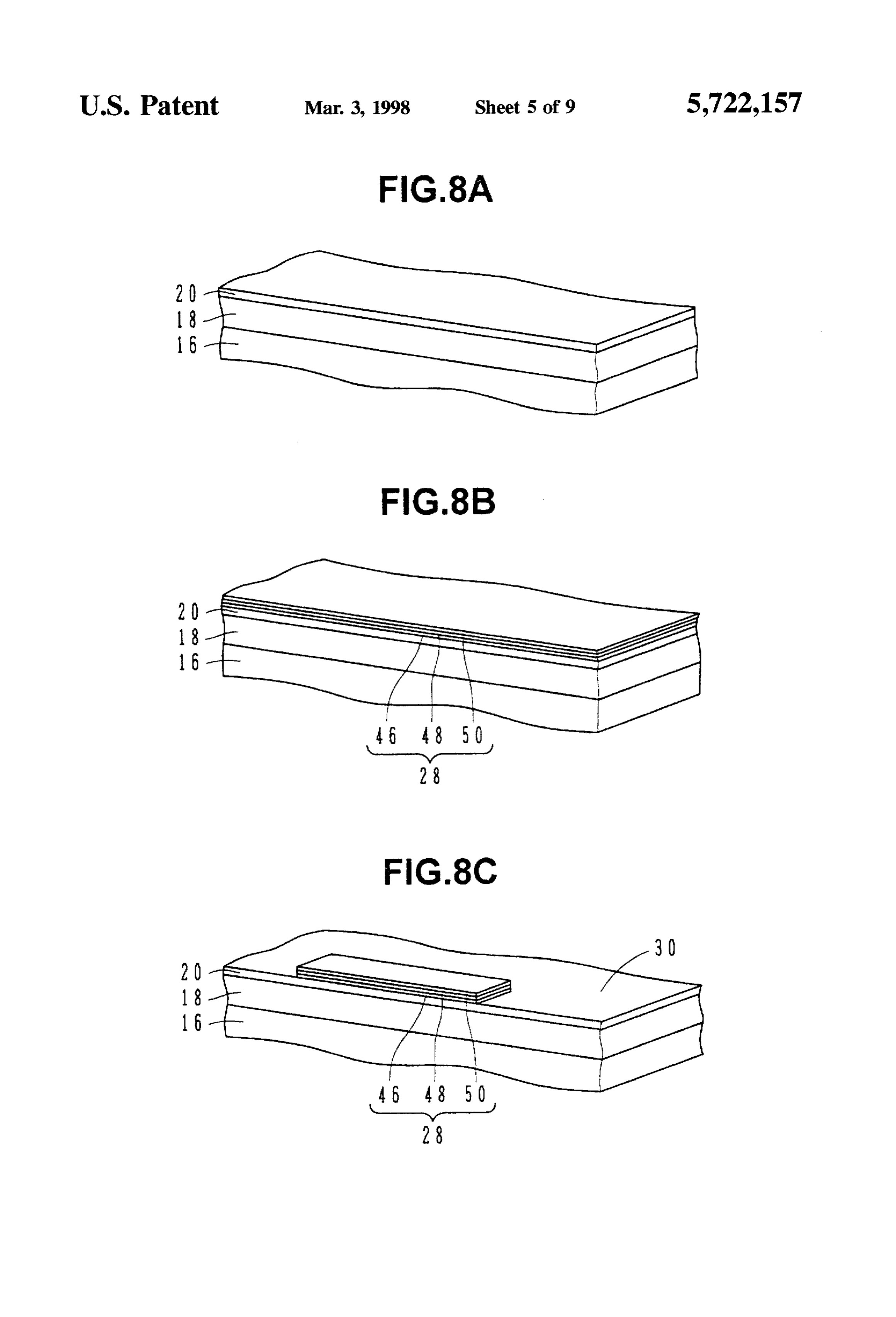
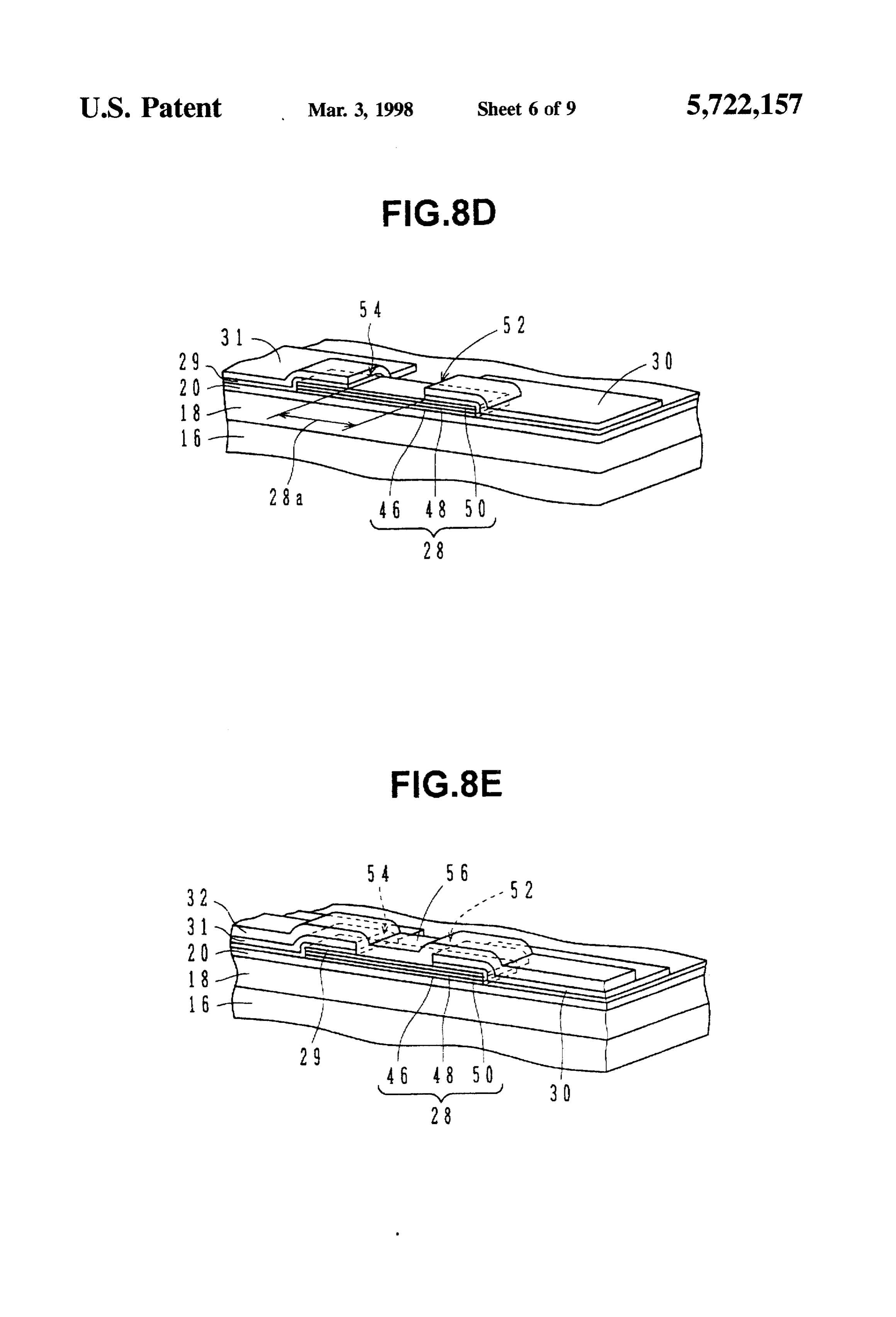
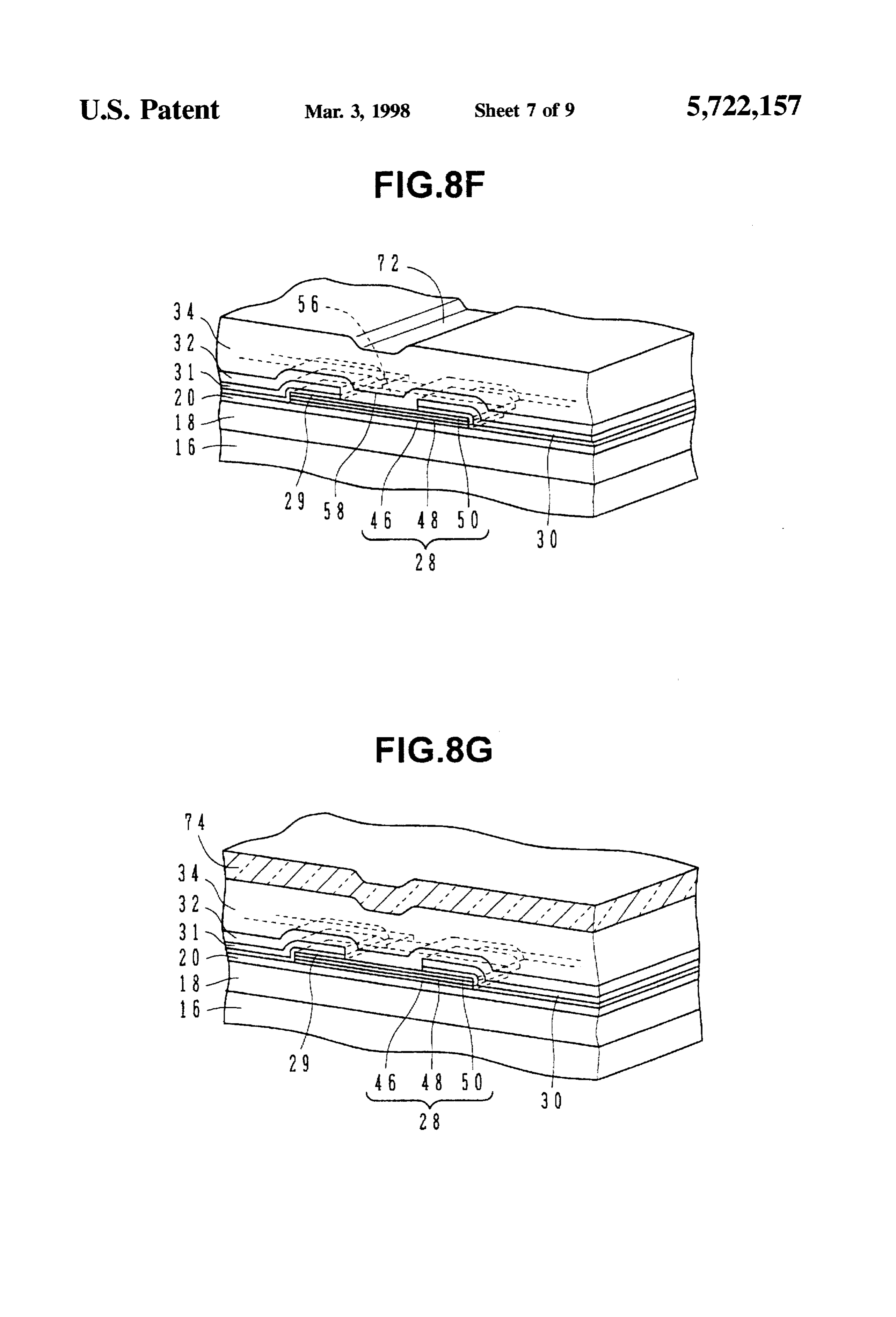
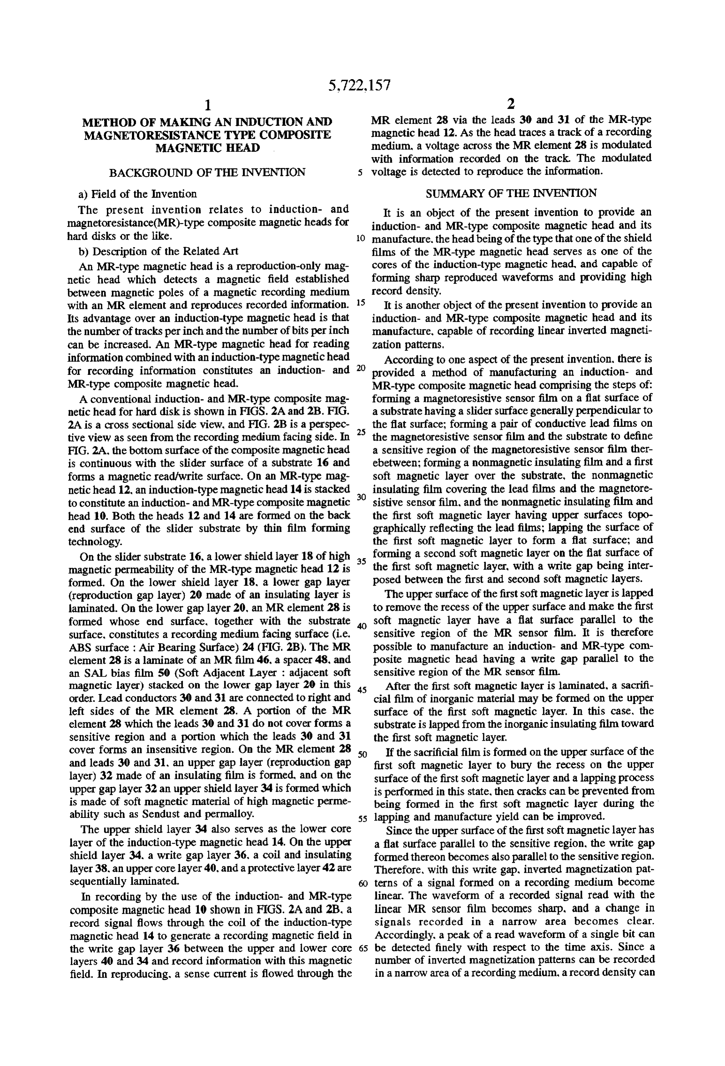
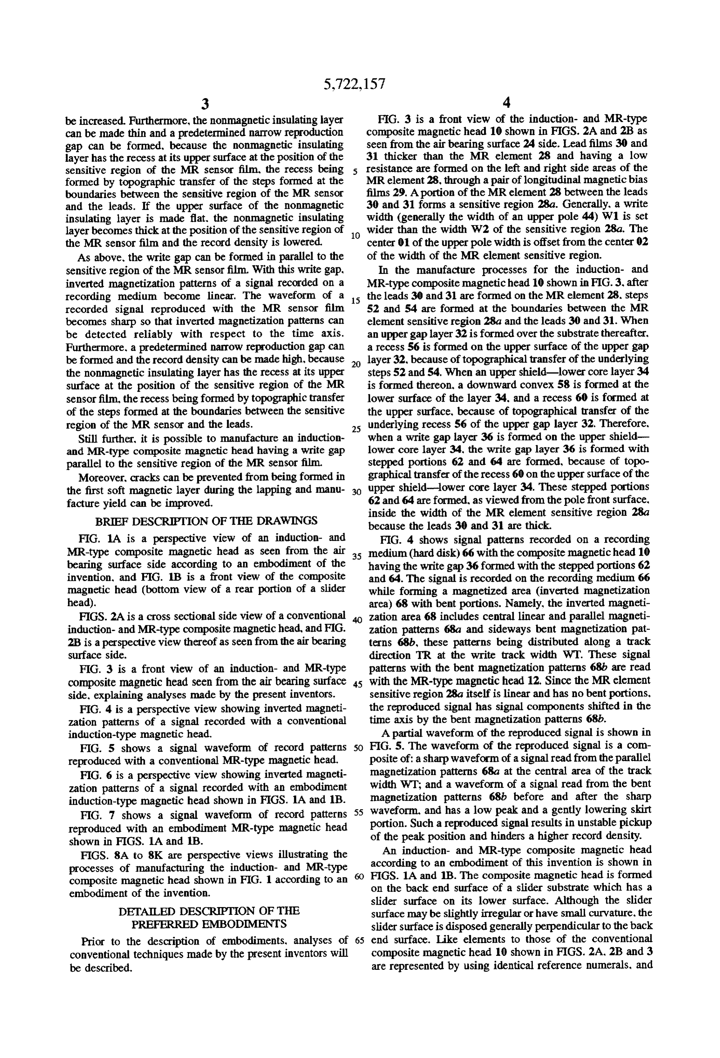
FIGS. 8A to 8K are perspective views illustrating the An induction- and MR-type composite magnetic head processes of manufacturing the induction- and MR-type according to an embodiment of this invention is shown in composite magnetic head shown in FIG. 1 according to an FIGS. 1A and 1B. The composite magnetic head is formed on the back end surface of a slider substrate which has a embodiment of the invention.
slider surface on its lower surface. Although the slider
DETALED DESCRIPTION OF THE surface may be slightly irregular or have small curvature. the PREFERRED EMBODIMENTS slider surface is disposed generally perpendicular to the back Prior to the description of embodiments, analyses of 65 end surface. Like elements to those of the conventional conventional techniques made by the present inventors will composite magnetic head 10 shown in FIGS. 2A, 2B and 3 be described. are represented by using identical reference numerals, and
Page 13
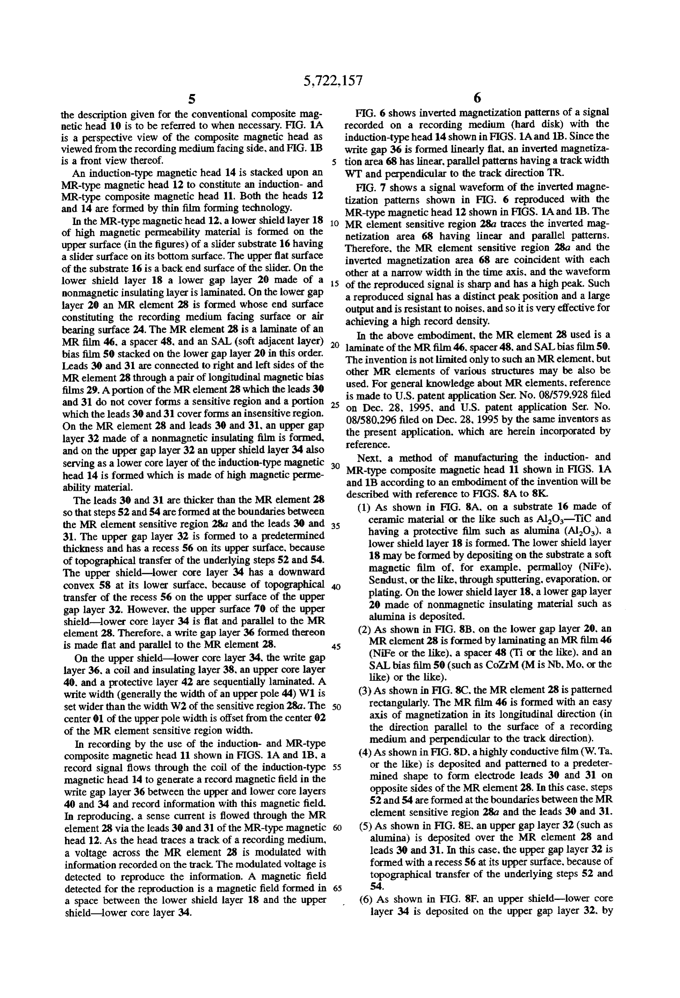
the description given for the conventional composite mag FIG. 6 shows inverted magnetization patterns of a signal netic head 10 is to be referred to when necessary. FIG. 1A recorded on a recording medium (hard disk) with the is a perspective view of the composite magnetic head as induction-type head 14 shown in FIGS. 1A and 1B. Since the viewed from the recording medium facing side, and FIG. 1B write gap 36 is formed linearly flat, an inverted magnetiza is a front view thereof. 5 tion area 68 has linear, parallel patterns having a track width An induction-type magnetic head 14 is stacked upon an WT and perpendicular to the track direction TR. MR-type magnetic head 12 to constitute an induction- and FIG. 7 shows a signal waveform of the inverted magne MR-type composite magnetic head 11. Both the heads 12 tization patterns shown in FIG. 6 reproduced with the and 14 are formed by thin film forming technology. MR-type magnetic head 12 shown in FIGS. 1A and 1B. The In the MR-type magnetic head 12, a lower shield layer 18 MR element sensitive region 28a traces the inverted mag of high magnetic permeability material is formed on the netization area 68 having linear and parallel patterns. upper surface (in the figures) of a slider substrate 16 having Therefore, the MR element sensitive region 28a and the a slider surface on its bottom surface. The upper flat surface inverted magnetization area 68 are coincident with each of the substrate 16 is a back end surface of the slider. On the other at a narrow width in the time axis, and the waveform lower shield layer 18 a lower gap layer 20 made of a 15 of the reproduced signal is sharp and has a high peak. Such nonmagnetic insulating layer is laminated. On the lower gap a reproduced signal has a distinct peak position and a large layer 20 an MR element 28 is formed whose end surface constituting the recording medium facing surface or air output and is resistant to noises, and so it is very effective for achieving a high record density.
bearing surface 24. The MR element 28 is a laminate of an In the above embodiment, the MR element 28 used is a MR film 46, a spacer 48, and an SAL (soft adjacent layer) 20 laminate of the MR film 46, spacer 48, and SAL bias film.50. bias film 50 stacked on the lower gap layer 20 in this order. The invention is not limited only to such an MR element, but Leads 30 and 31 are connected to right and left sides of the other MR elements of various structures may be also be MR element 28through a pair of longitudinal magnetic bias used. For general knowledge about MR elements, reference films 29. A portion of the MR element 28 which the leads 30 is made to U.S. patent application Ser. No. 08/579.928 filed and 31 do not cover forms a sensitive region and a portion 25 on Dec. 28, 1995, and U.S. patent application Ser. No. which the leads 30 and 31 coverforms an insensitive region. 08/580,296 filed on Dec. 28, 1995 by the On the MR element 28 and leads 30 and 31, an upper gap the present application. which are hereinsame inventors as incorporated by layer 32 made of a nonmagnetic insulating film is formed, reference.
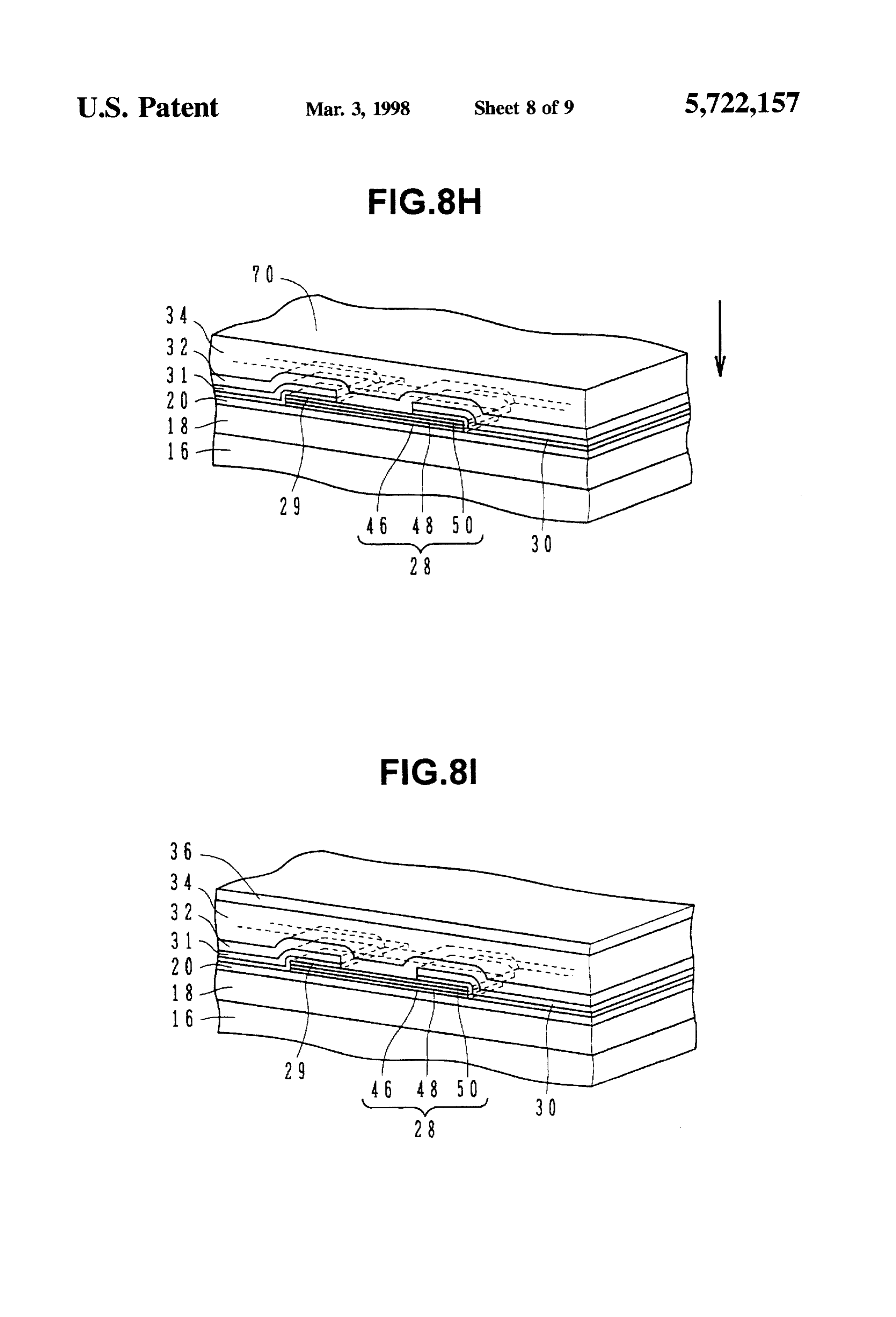
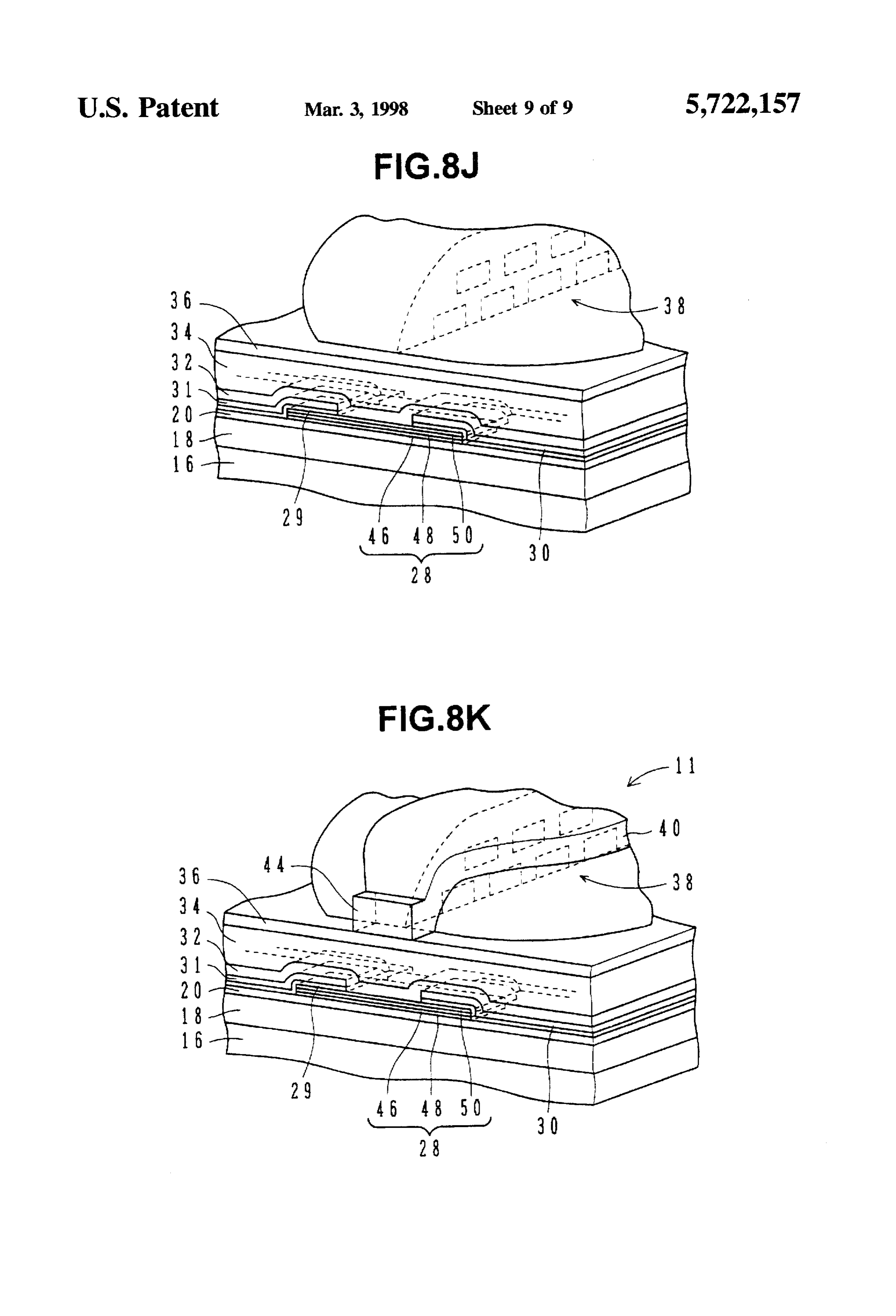
and on the upper gap layer 32 an upper shield layer 34 also Next, a method of manufacturing the induction- and serving as a lower core layer of the induction-type magnetic 30 MR-type composite magnetic head 11 shown in FIGS. 1A head 14 is formed which is made of high magnetic perme and 1B according to an embodiment of the invention will be ability material. described with reference to FIGS. 8A to 8K. The leads 30 and 31 are thicker than the MR element 28 so that steps 52 and 54 are formed at the boundaries between (1) As shown in FIG. 8A, on a substrate 16 made of the MR element sensitive region 28a and the leads 30 and 35 ceramic material or the like such as Al2O-TiC and 31. The upper gap layer 32 is formed to a predetermined having a protective film such as alumina (Al2O), a thickness and has a recess 56 on its upper surface, because lower shield layer 18 is formed. The lower shield layer of topographical transfer of the underlying steps 52 and 54. 18 may beformed by depositing on the substrate a soft The upper shield-lower core layer 34 has a downward magnetic film of, for example, permalloy (NiFe), convex 58 at its lower surface, because of topographical Sendust, or the like, through sputtering, evaporation, or transfer of the recess 56 on the upper surface of the upper plating. On the lower shield layer 18, a lower gap layer gap layer 32. However, the upper surface 70 of the upper 20 made of nonmagnetic insulating material such as shield-lower core layer 34 is flat and parallel to the MR alumina is deposited.
element 28. Therefore, a write gap layer 36 formed thereon (2) As shown in FIG. 8B, on the lower gap layer 20, an is made flat and parallel to the MR element 28. 45 MR element 28 is formed by laminating an MR film 46 On the upper shield-lower core layer 34, the write gap (NiFe or the like), a spacer 48 (Ti or the like), and an layer 36, a coil and insulating layer 38, an upper core layer SAL bias film 50 (such as CozrM (M is Nb, Mo, or the 40. and a protective layer 42 are sequentially laminated. A like) or the like).
write width (generally the width of an upper pole 44) W1 is (3) As shown in FIG. 8C. the MR element 28 is patterned set wider than the width W2 of the sensitive region 28a. The 50 rectangularly. The MR film 46 is formed with an easy center 01 of the upper pole width is offset from the center 02 axis of magnetization in its longitudinal direction (in of the MR element sensitive region width. the direction parallel to the surface of a recording In recording by the use of the induction- and MR-type medium and perpendicular to the track direction). composite magnetic head 11 shown in FIGS. 1A and 1B, a (4) As shown in FIG.8D, a highly conductive film (W. Ta, record signal flows through the coil of the induction-type 55 or the like) is deposited and patterned to a predeter magnetic head 14 to generate a record magnetic field in the mined shape to form electrode leads 30 and 31 on write gap layer 36 between the upper and lower core layers opposite sides of the MR element 28. In this case, steps 40 and 34 and record information with this magnetic field. 52 and 54 are formed at the boundaries between the MR In reproducing, a sense current is flowed through the MR element sensitive region 28a and the leads 30 and 31. element 28 via the leads 30 and 31 of the MR-type magnetic (5) As shown in FIG. 8E. an upper gap layer 32 (such as head 12. As the head traces a track of a recording medium, alumina) is deposited over the MR element 28 and a voltage across the MR element 28 is modulated with leads 30 and 31. In this case, the upper gap layer 32 is information recorded on the track. The modulated voltage is formed with a recess 56 at its upper surface, because of detected to reproduce the information. A magnetic field topographical transfer of the underlying steps 52 and detected for the reproduction is a magnetic field formed in 65 S4.
a space between the lower shield layer 18 and the upper (6) As shown in FIG. 8F. an upper shield-lower core shield-lower core layer 34. layer 34 is deposited on the upper gap layer 32, by
Page 14
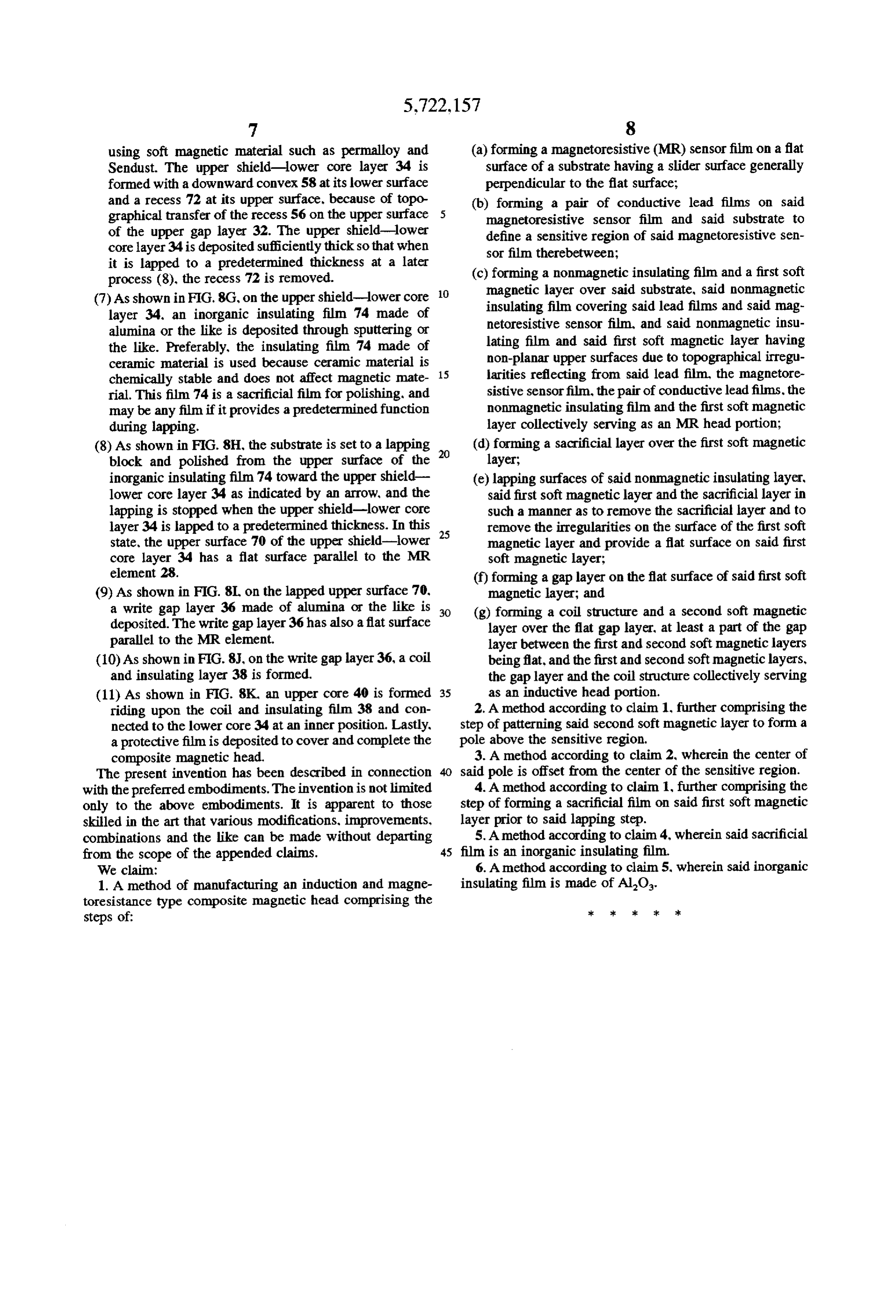
using soft magnetic material such as permalloy and (a) forming a magnetoresistive (MR) sensor film on a flat Sendust. The upper shield-lower core layer 34 is surface of a substrate having a slider surface generally formed with a downward convex 58 at its lower surface perpendicular to the flat surface; and a recess 72 at its upper surface, because of topo (b) forming a pair of conductive lead films on said graphical transfer of the recess 56 on the upper surface magnetoresistive sensor film and said substrate to of the upper gap layer 32. The upper shield-lower define a sensitive region of said magnetoresistive sen core layer 34 is deposited sufficiently thick so that when sor film therebetween;
it is lapped to a predetermined thickness at a later (c) forming a nonmagnetic insulating film and a first soft process (8), the recess 72 is removed. magnetic layer over said substrate, said nonmagnetic (7) As shown in FIG. 8G, on the upper shield-lower core 10 insulating film covering said lead films and said mag layer 34, an inorganic insulating film 74 made of netoresistive sensor film, and said nonmagnetic insu alumina or the like is deposited through sputtering or lating film and said first soft magnetic layer having the like. Preferably, the insulating film 74 made of non-planar upper surfaces due to topographical irregu ceramic material is used because ceramic material is chemically stable and does not affect magnetic mate 15 larities reflecting from said lead film, the magnetore rial. This film 74 is a sacrificial film for polishing, and sistive sensor film, the pair of conductive lead films, the may be any film if it provides a predetermined function nonmagnetic insulating film and the first soft magnetic during lapping. layer collectively serving as an MR head portion; (8) As shown in FIG. 8H, the substrate is set to a lapping 20 (d) forming a sacrificial layer over the first soft magnetic block and polished from the upper surface of the layer;
inorganic insulating film 74 toward the upper shield (e) lapping surfaces of said nonmagnetic insulating layer, lower core layer 34 as indicated by an arrow, and the said first soft magnetic layer and the sacrificial layer in lapping is stopped when the upper shield-lower core such a manner as to remove the sacrificial layer and to layer 34 is apped to a predetermined thickness. In this 25 remove the irregularities on the surface of the first soft state, the upper surface 70 of the upper shield-lower magnetic layer and provide a flat surface on said first core layer 34 has a flat surface parallel to the MR soft magnetic layer;
element 28. (f) forming a gap layer on the flat surface of said first soft (9) As shown in FIG. 8L, on the lapped upper surface 70, magnetic layer; and a write gap layer 36 made of alumina or the like is 30 (g) forming a coil structure and a second soft magnetic deposited. The write gap layer 36 has also a flat surface layer over the flat gap layer, at least a part of the gap parallel to the MR element. layer between the first and second soft magnetic layers (10) As shown in FIG.8.J. on the write gap layer 36, a coil being flat, and the first and second soft magnetic layers, and insulating layer 38 is formed. the gap layer and the coil structure collectively serving (11). As shown in FIG. 8K, an upper core 40 is formed 35 as an inductive head portion. riding upon the coil and insulating film 38 and con 2. A method according to claim 1, further comprising the nected to the lower core 34 at an inner position. Lastly, step of patterning said second soft magnetic layer to form a a protective film is deposited to cover and complete the pole above the sensitive region.
composite magnetic head. 3. A method according to claim 2, wherein the center of The present invention has been described in connection said pole is offset from the center of the sensitive region. with the preferred embodiments. The invention is not limited 4. A method according to claim 1, further comprising the only to the above embodiments. It is apparent to those step of forming a sacrificial film on said first soft magnetic skilled in the art that various modifications, improvements. layer prior to said lapping step.
combinations and the like can be made without departing 5. A method according to claim 4, wherein said sacrificial from the scope of the appended claims. 45 film is an inorganic insulating film. We claim: 6. A method according to claim 5, wherein said inorganic 1. A method of manufacturing an induction and magne insulating film is made of Al-O.
toresistance type composite magnetic head comprising the steps of: *k at :: :: *k
Provenance
- Collection
- Cited prior art
- Original PDF
- patentimages.storage.googleapis.com →
- Filed
- 1996-06-25
- Pages
- 14
- Method
- pdftotext (the PDF's own text layer) + pdftoppm 300dpi page scans
- Source
- Google Patents bibliographic record
- Granted
- 1998-03-03
- Inventors
- Shigeru Shouji; Atsushi Toyoda; Yamaha Corp
- Transcribed from
- patentimages.storage.googleapis.com →