patent · US3996919
System for collecting and storing solar energy
14 December 1976
Page 1 — bibliographic record
United States Patent to 11, 3,996,919 Hepp 45 Dec. 14, 1976 (54) SYSTEM FOR COLLECTING AND STORING 57 ABSTRACT SOLAR ENERGY A system for collecting and storing solar energy which 75 Inventor: Peter S. Hepp, Media, Pa. includes solar panels which are installed between the 73) Assignee: Sun Oil Company of Pennsylvania, joists of the roof so that the collector surface of each Philadelphia, Pa. panel acts as part of the roof of each panel, and also includes a heat storage system connected to the back 22 Filed: Nov. 21, 1975 side of each panel. Each heat storage system has a plurality of heat storage cylinders containing a phase (21) Appl. No.: 634,229 change, heat storage mixture and a heat pipe for con 52 U.S. Cl. ............................... 126/270; 126/400; ducting the heat collected by the collector surface to 165/105; 237/1 A the heat storage material. The containers of heat stor 51) int. Cl............................................. F24J 3/02 age material extend into ductwork connected to a con 58 Field of Search .................. 126/270, 271, 400; ventional forced air heating system so that the air is 237/1 A; 165/105, 18; 60/641; 202/234 heated when it is circulated around the heat storage 56 References Cited cylinders. The heat storage system can be used with a flat solar collector surface as well as with a parabolic
UNITED STATES PATENTS reflector for focusing sunlight on the end of the heat 1971,242 8/1934 Wheeler ............................ 126/27-1 pipe. An alternative embodiment uses individual solar 3,799,144 3/1974 Ramsey et al. ........ ... 26/270 absorbing panels for each heat pipe which permits 3,875,926 4/1975 Frank ................. ... 126/27 alignment of the collector surface in the most efficient 3,923,038 2/1975 Cutchaw ............................ 126/27 direction.
Primary Examiner-Kenneth W. Sprague
Assistant Examiner-James C. Yeung
Attorney, Agent, or Firm-J. Edward Hess; Donald R.
Johnson; Gary V. Pack 7 Claims, 8 Drawing Figures
HEATER
CONTROL
SYSTEM
COLLECTOR
CONTROL
CIRCUIT
Page 2
Drawing sheet — no readable text.
Page 3
Drawing sheet — no readable text.
Page 4
Drawing sheet — no readable text.
Page 5
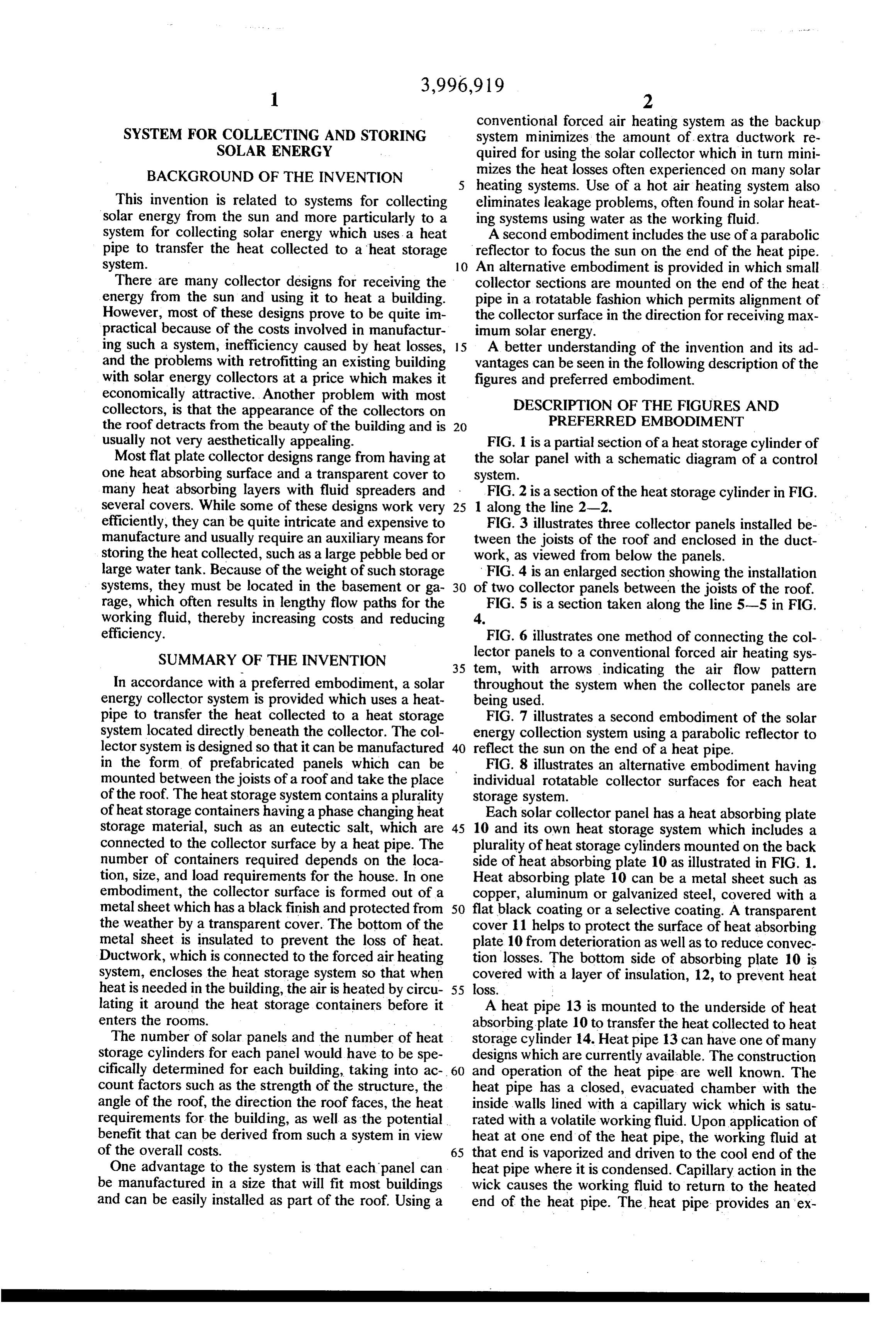
conventional forced air heating system as the backup
SYSTEM FOR COLLECTING AND STORING system minimizes the amount of extra ductwork re SOLAR ENERGY quired for using the solar collector which in turn mini BACKGROUND OF THE INVENTION mizes the heat losses often experienced on many solar heating systems. Use of a hot air heating system also
This invention is related to systems for collecting eliminates leakage problems, often found in solar heat solar energy from the sun and more particularly to a ing systems using water as the working fluid. system for collecting solar energy which uses a heat A second embodiment includes the use of a parabolic pipe to transfer the heat collected to a heat storage reflector to focus the sun on the end of the heat pipe. system. 10 An alternative embodiment is provided in which small There are many collector designs for receiving the collector sections are mounted on the end of the heat; energy from the sun and using it to heat a building. pipe in a rotatable fashion which permits alignment of However, most of these designs prove to be quite im the collector surface in the direction for receiving max practical because of the costs involved in manufactur imum solar energy.
ing such a system, inefficiency caused by heat losses, 15 A better understanding of the invention and its ad and the problems with retrofitting an existing building vantages can be seen in the following description of the with solar energy collectors at a price which makes it figures and preferred embodiment.
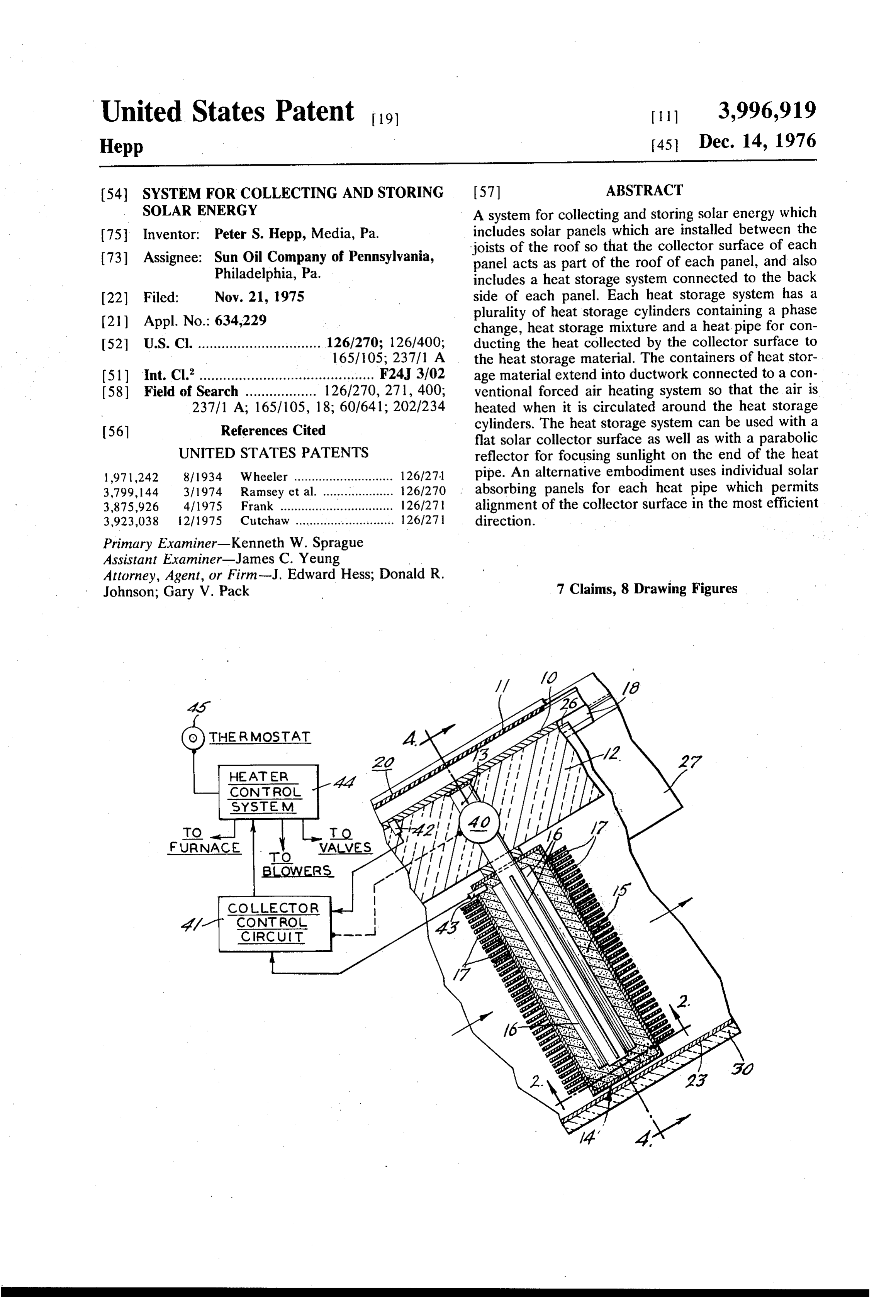
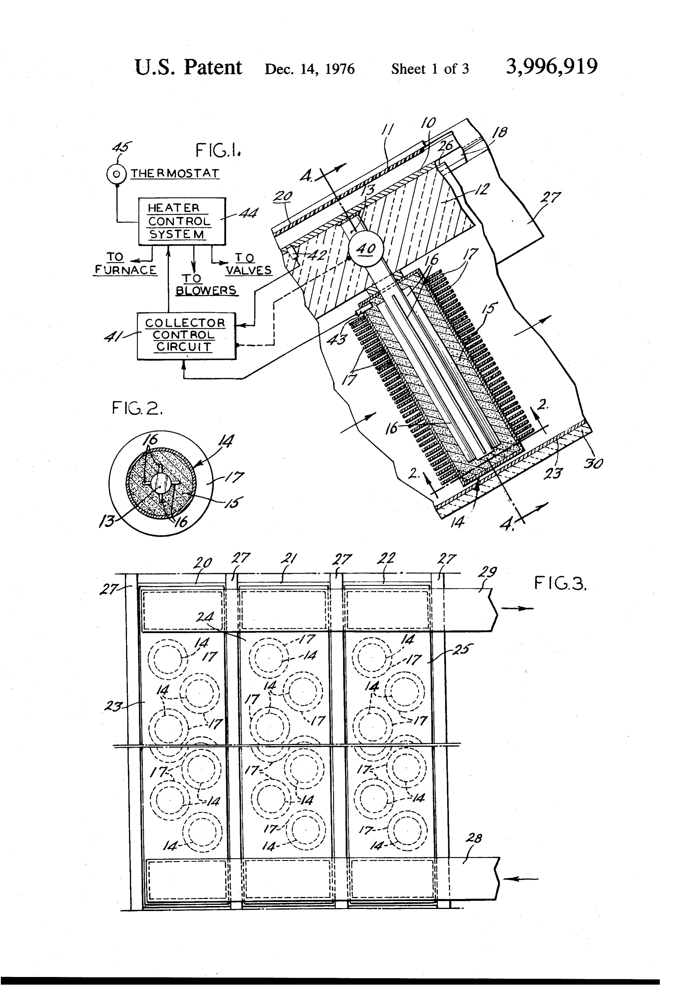
economically attractive. Another problem with most DESCRIPTION OF THE FIGURES AND collectors, is that the appearance of the collectors on PREFERRED EMBODIMENT the roof detracts from the beauty of the building and is 20 usually not very aesthetically appealing. FIG. 1 is a partial section of a heat storage cylinder of Most flat plate collector designs range from having at the solar panel with a schematic diagram of a control one heat absorbing surface and a transparent cover to system.
many heat absorbing layers with fluid spreaders and FIG. 2 is a section of the heat storage cylinder in FIG. several covers. While some of these designs work very 25 1 along the line 2-2.
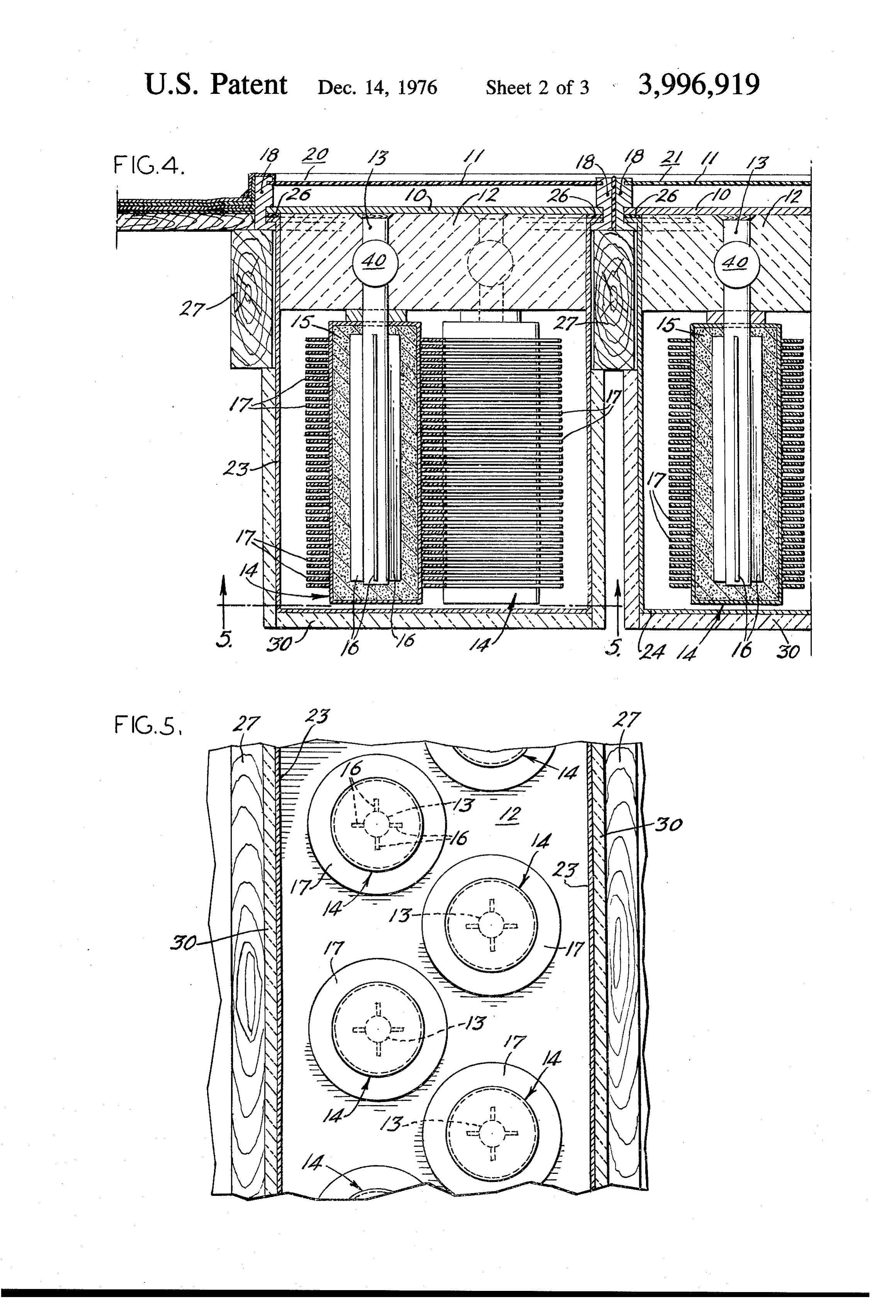
efficiently, they can be quite intricate and expensive to FIG. 3 illustrates three collector panels installed be manufacture and usually require an auxiliary means for tween the joists of the roof and enclosed in the duct storing the heat collected, such as a large pebble bed or work, as viewed from below the panels. large water tank. Because of the weight of such storage FIG. 4 is an enlarged section showing the installation systems, they must be located in the basement orga 30 of two collector panels between the joists of the roof. rage, which often results in lengthy flow paths for the FIG. 5 is a section taken along the line 5-5 in FIG. working fluid, thereby increasing costs and reducing 4.
efficiency. FIG. 6 illustrates one method of connecting the col SUMMARY OF THE INVENTION lector panels to a conventional forced air heating sys 35 tem, with arrows indicating the air flow pattern
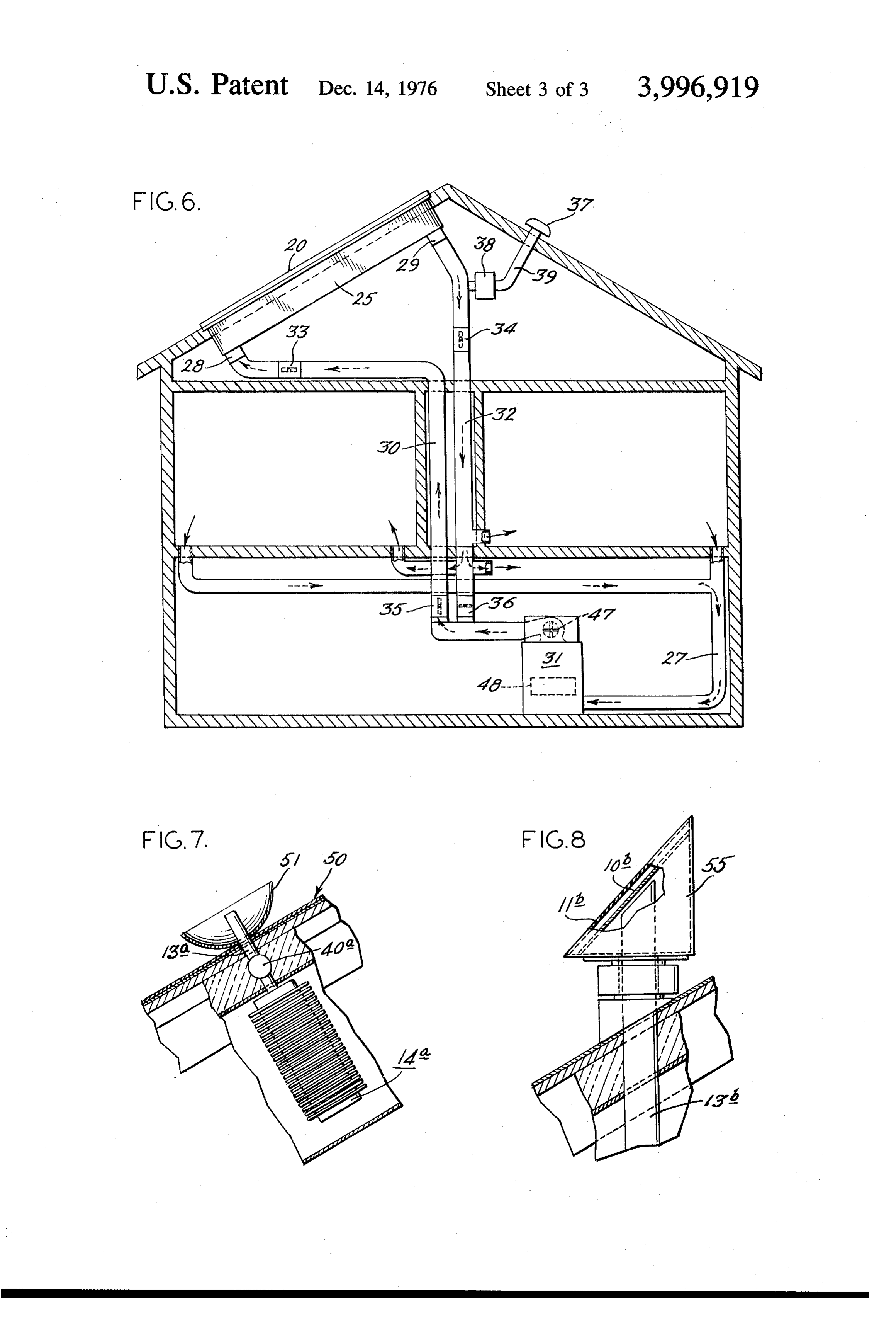
In accordance with a preferred embodiment, a solar throughout the system when the collector panels are energy collector system is provided which uses a heat being used.
pipe to transfer the heat collected to a heat storage FIG. 7 illustrates a second embodiment of the solar system located directly beneath the collector. The col energy collection system using a parabolic reflector to lector system is designed so that it can be manufactured 40 reflect the sun on the end of a heat pipe. in the form of prefabricated panels which can be FIG. 8 illustrates an alternative embodiment having mounted between the joists of a roof and take the place individual rotatable collector surfaces for each heat of the roof. The heat storage system contains a plurality storage system.
of heat storage containers having a phase changing heat Each solar collector panel has a heat absorbing plate storage material, such as an eutectic salt, which are 45 10 and its own heat storage system which includes a connected to the collector surface by a heat pipe. The plurality of heat storage cylinders mounted on the back number of containers required depends on the loca side of heat absorbing plate 10 as illustrated in FIG. 1. tion, size, and load requirements for the house. In one Heat absorbing plate 10 can be a metal sheet such as embodiment, the collector surface is formed out of a copper, aluminum or galvanized steel, covered with a metal sheet which has a black finish and protected from 50 flat black coating or a selective coating. A transparent the weather by a transparent cover. The bottom of the cover 11 helps to protect the surface of heat absorbing metal sheet is insulated to prevent the loss of heat. plate 10 from deterioration as well as to reduce convec Ductwork, which is connected to the forced air heating tion losses. The bottom side of absorbing plate 10 is system, encloses the heat storage system so that when covered with a layer of insulation, 12, to prevent heat heat is needed in the building, the air is heated by circu 55 loss.
lating it around the heat storage containers before it A heat pipe 13 is mounted to the underside of heat enters the rooms. , absorbing plate 10 to transfer the heat collected to heat The number of solar panels and the number of heat storage cylinder 14. Heat pipe 13 can have one of many storage cylinders for each panel would have to be spe designs which are currently available. The construction cifically determined for each building, taking into ac 60 and operation of the heat pipe are well known. The count factors such as the strength of the structure, the heat pipe has a closed, evacuated chamber with the angle of the roof, the direction the roof faces, the heat inside walls lined with a capillary wick which is satu requirements for the building, as well as the potential rated with a volatile working fluid. Upon application of benefit that can be derived from such a system in view heat at one end of the heat pipe, the working fluid at of the overall costs. 65 that end is vaporized and driven to the cool end of the One advantage to the system is that each panel can heat pipe where it is condensed. Capillary action in the be manufactured in a size that will fit most buildings wick causes the working fluid to return to the heated and can be easily installed as part of the roof. Using a end of the heat pipe. The heat pipe provides an ex
Page 6
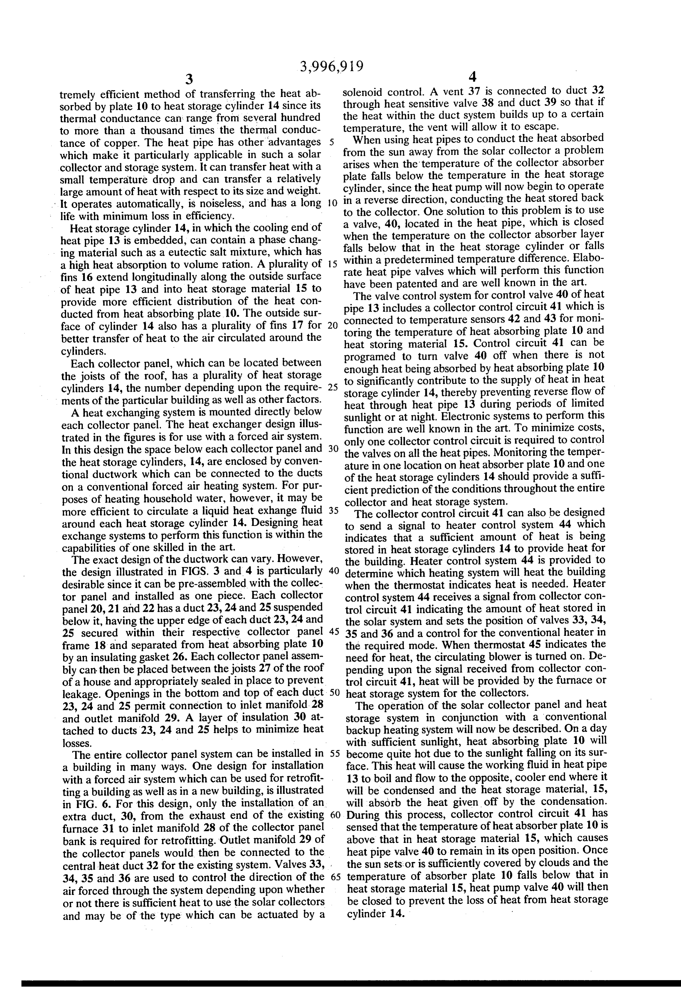
tremely efficient method of transferring the heat ab solenoid control. A vent 37 is connected to duct 32 sorbed by plate 10 to heat storage cylinder 14 since its through heat sensitive valve 38 and duct 39 so that if thermal conductance can range from several hundred the heat within the duct system builds up to a certain temperature, the vent will allow it to escape.
to more than a thousand times the thermal conduc tance of copper. The heat pipe has other advantages 5 When using heat pipes to conduct the heat absorbed which make it particularly applicable in such a solar from the sun away from the solar collector a problem collector and storage system. It can transfer heat with a arises falls when the temperature of the collector absorber small temperature drop and can transfer a relatively plate cylinder, below the temperature in the heat storage since the heat pump will now begin to operate large amount of heat with respect to its size and weight. in a reverse direction, conducting the heat stored back It operates automatically, is noiseless, and has a long 10 to the collector. One solution to this problem is to use life with minimum loss in efficiency.
Heat storage cylinder 14, in which the cooling end of awhen valve, 40, located in the heat pipe, which is closed the temperature on the collector absorber layer heat pipe 13 is embedded, can contain a phase chang ing material such as a eutectic salt mixture, which has falls below that in the heat storage cylinder or falls a high heat absorption to volume ration. A plurality of 15 within a predetermined temperature difference. Elabo fins 16 extend longitudinally along the outside surface have beenpipe rate heat valves which will perform this function patented and are well known in the art.
of heat pipe 13 and into heat storage material 15 to The valve control system for control valve 40 of heat provide more efficient distribution of the heat con pipe 13 includes a collector control circuit 41 which is ducted from heat absorbing plate 10. The outside sur connected to temperature sensors 42 and 43 for moni face of cylinder 14 also has a plurality of fins 17 for 20 toring the temperature of heat absorbing plate 10 and better transfer of heat to the air circulated around the cylinders. heat storing material 15. Control circuit 41 can be Each collector panel, which can be located between enough heat being absorbed40by off programed to turn valve heat when there is not absorbing plate 10 the joists of the roof, has a plurality of heat storage to significantly contribute to the supply of heat in heat cylinders 14, the number depending upon the require- 25 storage cylinder 14, thereby preventing reverse flow of ments of the particular building as well as other factors. heat through heat pipe 13 during periods of limited A heat exchanging system is mounted directly below each collector panel. The heat exchanger design illus sunlight or at night. Electronic systems to perform this function are well known in the art. To minimize costs, trated in the figures is for use with a forced air system. only one collector control circuit is required to control In this design the space below each collector panel and 30 the valves on all the heat pipes. Monitoring the temper the heat storage cylinders, 14, are enclosed by conven ature in one location on heat absorber plate 10 and one tional ductwork which can be connected to the ducts of the heat storage cylinders 14 should provide a suffi on a conventional forced air heating system. For pur cient prediction of the conditions throughout the entire poses of heating household water, however, it may be collector and heat storage system.
more efficient to circulate a liquid heat exhange fluid 35 The collector control circuit 41 can also be designed around each heat storage cylinder 14. Designing heat to send a signal to heater control system 44 which exchange systems to perform this function is within the indicates that a sufficient amount of heat is being capabilities of one skilled in the art. stored in heat storage cylinders 14 to provide heat for The exact design of the ductwork can vary. However, the building. Heater control system 44 is provided to the design illustrated in FIGS. 3 and 4 is particularly 40 determine which heating system will heat the building desirable since it can be pre-assembled with the collec when the thermostat indicates heat is needed. Heater tor panel and installed as one piece. Each collector control system 44 receives a signal from collector con panel 20, 21 and 22 has a duct 23, 24 and 25 suspended trol circuit 41 indicating the amount of heat stored in below it, having the upper edge of each duct 23, 24 and the solar system and sets the position of valves 33, 34, 25 secured within their respective collector panel 45 35 and 36 and a control for the conventional heater in frame 18 and separated from heat absorbing plate 10 the required mode. When thermostat 45 indicates the by an insulating gasket 26. Each collector panel assem need for heat, the circulating blower is turned on. De bly can then be placed between the joists 27 of the roof pending upon the signal received from collector con of a house and appropriately sealed in place to prevent trol circuit 41, heat will be provided by the furnace or leakage. Openings in the bottom and top of each duct 50 heat storage system for the collectors. 23, 24 and 25 permit connection to inlet manifold 28 The operation of the solar collector panel and heat and outlet manifold 29. A layer of insulation 30 at storage system in conjunction with a conventional tached to ducts 23, 24 and 25 helps to minimize heat backup heating system will now be described. On a day losses. with sufficient sunlight, heat absorbing plate 10 will The entire collector panel system can be installed in 55 become quite hot due to the sunlight falling on its sur a building in many ways. One design for installation face. This heat will cause the working fluid in heat pipe with a forced air system which can be used for retrofit 13 to boil and flow to the opposite, cooler end where it ting a building as well as in a new building, is illustrated will be condensed and the heat storage material, 15, in FIG. 6. For this design, only the installation of an will absorb the heat given off by the condensation. extra duct, 30, from the exhaust end of the existing 60 During this process, collector control circuit 41 has furnace 31 to inlet manifold 28 of the collector panel sensed that the temperature of heat absorber plate 10 is bank is required for retrofitting. Outlet manifold 29 of above that in heat storage material 15, which causes the collector panels would then be connected to the heat pipe valve 40 to remain in its open position. Once central heat duct 32 for the existing system. Valves 33, the sun sets or is sufficiently covered by clouds and the 34, 35 and 36 are used to control the direction of the 65 temperature of absorber plate 10 falls below that in air forced through the system depending upon whether heat storage material 15, heat pump valve 40 will then or not there is sufficient heat to use the solar collectors be closed to prevent the loss of heat from heat storage and may be of the type which can be actuated by a cylinder 14.
Page 7
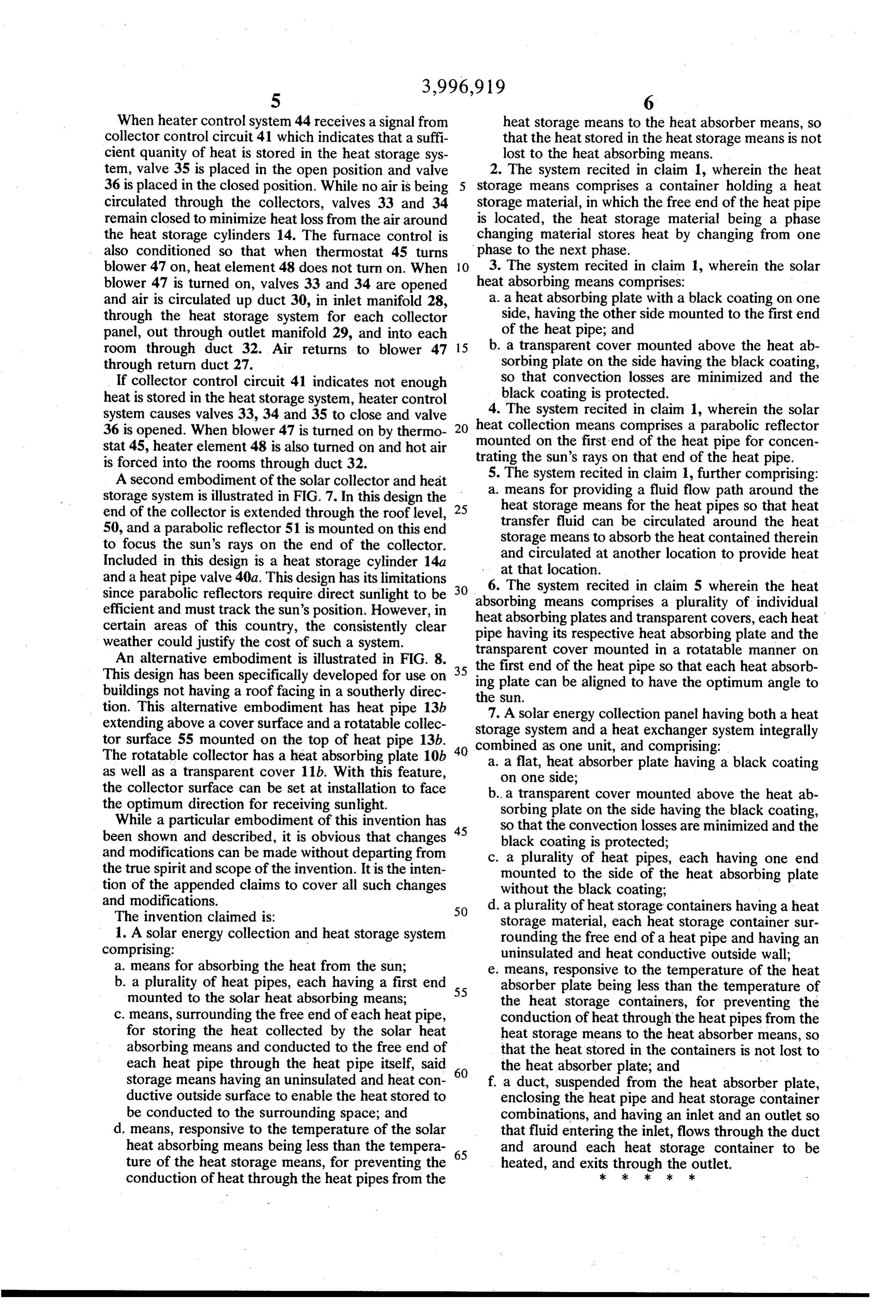
When heater control system 44 receives a signal from heat storage means to the heat absorber means, so collector control circuit 41 which indicates that a suffi that the heat stored in the heat storage means is not cient quanity of heat is stored in the heat storage sys lost to the heat absorbing means. tem, valve 35 is placed in the open position and valve 2. The system recited in claim 1, wherein the heat 36 is placed in the closed position. While no air is being 5 storage means comprises a container holding a heat circulated through the collectors, valves 33 and 34 storage material, in which the free end of the heat pipe remain closed to minimize heat loss from the air around is located, the heat storage material being a phase the heat storage cylinders 14. The furnace control is changing material stores heat by changing from one also conditioned so that when thermostat 45 turns phase to the next phase.
blower 47 on, heat element 48 does not turn on. When 10 3. The system recited in claim 1, wherein the solar blower 47 is turned on, valves 33 and 34 are opened heat absorbing means comprises:
and air is circulated up duct 30, in inlet manifold 28, a. a heat absorbing plate with a black coating on one through the heat storage system for each collector side, having the other side mounted to the first end panel, out through outlet manifold 29, and into each of the heat pipe; and room through duct 32. Air returns to blower 47 15 b. a transparent cover mounted above the heat ab through return duct 27. sorbing plate on the side having the black coating, If collector control circuit 41 indicates not enough so that convection losses are minimized and the heat is stored in the heat storage system, heater control black coating is protected. system causes valves 33, 34 and 35 to close and valve heat 4. The system recited in claim 1, wherein the solar 36 is opened. When blower 47 is turned on by thermo 20 mounted collection means comprises a parabolic reflector stat 45, heater element 48 is also turned on and hot air on the first end of the heat pipe for concen is forced into the rooms through duct 32. trating the sun's rays on that end of the heat pipe. A second embodiment of the solar collector and heat 5. The system recited in claim 1, further comprising: storage system is illustrated in FIG. 7. In this design the a means for providing a fluid flow path around the end of the collector is extended through the roof level, 25 heat storage means for the heat pipes so that heat transfer fluid can be circulated around the heat 50, and a parabolic reflector 51 is mounted on this end storage means to absorb the heat contained therein to focus the sun's rays on the end of the collector. and circulated at another location to provide heat Included in this design is a heat storage cylinder 14a and a heat pipe valve 40a. This design has its limitations 30 6.atThe that location.
since parabolic reflectors require direct sunlight to be absorbingsystem recited in claim 5 wherein the heat means comprises a plurality of individual efficient and must track the sun's position. However, in heat absorbing certain areas of this country, the consistently clear pipe having its plates and transparent covers, each heat respective heat absorbing plate and the weather could justify the cost of such a system. transparent cover mounted in a rotatable manner on An alternative embodiment is illustrated in FIG. 8.
This design has been specifically developed for use on 35 the first end of the heat pipe so that each heat absorb buildings not having a roof facing in a southerly direc the sun. can be aligned to have the optimum angle to ing plate tion. This alternative embodiment has heat pipe 13b 7. A solar energy collection panel having both a heat extending above a cover surface and a rotatable collec storage system and a heat exchanger system integrally tor surface 55 mounted on the top of heat pipe 13b. 40 combined as one unit, and comprising: The rotatable collector has a heat absorbing plate 10b a. a flat, heat absorber plate having a black coating as well as a transparent cover 11b. With this feature, on one side;
the collector surface can be set at installation to face b. a transparent cover mounted above the heat ab the optimum direction for receiving sunlight. sorbing plate on the side having the black coating, While a particular embodiment of this invention has so that the convection losses are minimized and the been shown and described, it is obvious that changes 45 black coating is protected; and modifications can be made without departing from c. a plurality of heat pipes, each having one end the true spirit and scope of the invention. It is the inten mounted to the side of the heat absorbing plate tion of the appended claims to cover all such changes without the black coating; and modifications.
The invention claimed is: 50 d. a plurality of heat storage containers having a heat storage material, each heat storage container sur 1. A solar energy collection and heat storage system rounding the free end of a heat pipe and having an comprising: uninsulated and heat conductive outside wall; a. means for absorbing the heat from the sun; e. means, responsive to the temperature of the heat b. a plurality of heat pipes, each having a first end 55 absorber plate being less than the temperature of mounted to the solar heat absorbing means; the heat storage containers, for preventing the c. means, surrounding the free end of each heat pipe, conduction of heat through the heat pipes from the for storing the heat collected by the solar heat heat storage means to the heat absorber means, so absorbing means and conducted to the free end of that the heat stored in the containers is not lost to each heat pipe through the heat pipe itself, said 60 the heat absorber plate; and storage means having an uninsulated and heat con f. a duct, suspended from the heat absorber plate, ductive outside surface to enable the heat stored to enclosing the heat pipe and heat storage container be conducted to the surrounding space; and combinations, and having an inlet and an outlet so d. means, responsive to the temperature of the solar that fluid entering the inlet, flows through the duct heat absorbing means being less than the tempera 65 and around each heat storage container to be ture of the heat storage means, for preventing the heated, and exitsck through the outlet. conduction of heat through the heat pipes from the k k k sk
Provenance
- Collection
- Cited prior art
- Original PDF
- patentimages.storage.googleapis.com →
- Filed
- 1975-11-21
- Pages
- 7
- Method
- pdftotext (the PDF's own text layer) + pdftoppm 300dpi page scans
- Source
- Google Patents bibliographic record
- Granted
- 1976-12-14
- Inventors
- Peter S. Hepp; Sun Oil Company of Pennsylvania
- Transcribed from
- patentimages.storage.googleapis.com →