patent · US3584850
Rotary kiln for shock sintering
15 June 1971
Page 1 — bibliographic record
United States Patent (11) 3,584,850 (72) inventors William W. Brandvold ing the raw material pellets to a temperature below the reac Gary, Ind; tion temperature. The rotary kiln has a reaction zone adjacent Stewart W. Tresouthick, Allison Park, Pa. the other end of the rotary kiln for heating the raw material (21) Appl. No. 838,560 pellets above the reaction temperature to pyroprocess the raw 22 Filed July 2, 1969 material pellets into the sinter. Restriction means are between (45) Patented June 15, 1971 the preheating zone and the reaction zone for damming a 73) Assignee United States Steel Corporation reservoir of the raw material pellets adjacent the restriction means so that the reservoir of the raw material pellets is pro tected from the direct radiation of the heated fluid and the (54) ROTARY KILN FOR SHOCK SENTERING temperature of the reservoir of raw material pellets remains 20 Claims, 6 Drawing Figs.
unaffected by instantaneous changes in the temperature of the (52) U.S.C....................................................... 263/32 heated fluid, the restriction means' being operable to meter 51) int.C......................................................... F27b.7100 minimum layers of the raw material pellets into the reaction 50 Field of Search............................................ 263/32,53 zone so that the minimum layers of the raw material pellets are
individually and rapidly heated to the reaction temperature by the heated fluid and the raw material pellets are converted
UNITED STATES PATENTS into sinter.
1,071 ,303 8/1913 Dreisbach et al............. 263/32X The method includes the steps of receiving the raw material 2,410,598 11/1946 Cliffe............... 263/32 pellets at one end of a rotary kiln and moving the raw material 2,823,910 2/1958 Ravasio........................ 263/32 pellets along a path of movement in the rotary kiln to the other Primary Examiner-John J. Camby end of the rotary kiln; directing a heated fluid through the ro Attorney-Robert J. Leek, Jr. tary kiln; heating the raw material pellets by the heated fluid adjacent the one end of the rotary kiln to substantially remove the moisture in the raw material pellets; mixing a cooling fluid with the heated fluid to limit the temperature (during the
ABSTRACT: This invention relates to a method of and ap removal of the moisture) below the temperature at which the paratus for pyroprocessing raw material having a reaction raw material pellets explode due to rapid heating to a deleteri temperature and containing moisture into sinter. ously high temperature; heating the raw material pellets in a The apparatus has a rotary kiln adapted to receive the raw preheating zone of the rotary kiln further along the path of material pellets at one end of the rotary kiln and to move the movement to a temperature below the reaction temperature; raw material pellets along a path of movement in the rotary damming a reservoir of the raw material pellets adjacent the kiln to the other end of the rotary kiln. Heating means are ad preheating zone and further along the path of movement so jacent the other end of the rotary kiln for directing a heated that the reservoir of the raw material pellets is protected from fluid through the rotary kiln, the rotary kiln having a drying the direct radiation of the heated fluid and the temperature of means adjacent the one end of the rotary kiln for heating the the reservoir of the raw material pellets remains unaffected by raw material pellets by the heated fluid to substantially instantaneous changes in the temperature of the heated fluid; remove the moisture in the raw material pellets. Cooling metering minimum layers of the raw material pellets adjacent means communicate with the drying means for mixing a cool the preheating zone and further along the path of movement ing fluid with the heated fluid to limit the temperature in the into a reaction zone of the rotary kiln adjacent the other end drying means below the temperature at which the raw material of the kiln; and heating raw material pellets individually and pellets explode due to rapid heating to a deleteriously high rapidly in the reaction zone of the rotary kiln to individually temperature. The rotary kiln has a preheating zone adjacent and rapidly heat the raw material pellets to the reaction tem the drying means further along the path of movement for heat perature by the heated fluid, thus converting the raw material pellets into the sinter.
SAPay
70 STOA as B/Ay
Page 2
Drawing sheet — no readable text.
Page 3
Drawing sheet — no readable text.
Page 4
Drawing sheet — no readable text.
Page 5
Drawing sheet — no readable text.
Page 6
Drawing sheet — no readable text.
Page 7
A method of pyroprocessing raw materials into a cementi
ROTARY KLN FOR SHOCK SNTERNG cious sinter is disclosed in U.S. Pat, application Ser. No.
BACKGROUND OF THE INVENTION
signed to the same assignee as the present application. The raw materials utilized may for example comprise; it. . . Typical rotary kilns employed in industry today are generally cylindrical in shape and rotate about their longitu . Percent dinal axis at approximately tr.p.m. The nominal size of such a SiO----------------------------------- Up to 6 kiln used in marking, for example, portland cement clinker Al2O3---------------------------------- 52 to 74 may be about 12 feet in diameter by about 450 feet long and O (including any TiO, which may be present) such kiln is inclined at an angle of about 3 from the horizon Percent tal. Cement raw materials are fed into the upper or elevated CaO---------------------------------- 23 to 42 end of the kiln in the form of either dry granulated powder, FeO3 a -- -- - - - - - - - - - - -- - - - -- - -- - - - - - - -- - - - 0.5 to 4
finely ground slurry or nodules. As the kiln rotates, the feed 15 Miscellaneous-------------------------- .0 to 5 moves slowly down the kiln often requiring about 3 hours to travel the length of the kiln. As the feed enters the kiln, it is ex Here, as in the other compositions given below, the percent posed to the hot exhaust gases passing countercurrent over the ages are by weight. In one preferred embodiment of that in material and, as the material traverses the length of the kiln, the temperature of the feed gradually rises. As the tempera 20 vention the composition of the raw materials is: ture increases, the moisture in the feed is driven off. Sub sequently, as the temperature of the feed increases to approxi SiO2----------------------------------- 4.Percent 5: .. 5 mately 1,600°F., calcination of the limestone begins and con AlO3-------------------------- - - - - - 631 tinues to completion prior to the feed entering the burning (including minor proportions of TiO2) zone, By the time the feed enters the burning zone, it has 25 CaO---------------------------------- 30, 7-1 reached a temperature of approximately 2,500F. and is at the Fe2O3------------------ - - - - - - - - - - - - - - - - 1. 02.8 point of incipient fusion. It is essential to the process, as it is Miscellaneous-------------------------- to 2 now practiced, that the temperature of the feed be raised at a uniform rate, hour after hour. Any change in the temperature In a second embodiment, the composition of the raw of the feed in relation to the thermal input will cause a change 30 materials is:
in the thermal balance of the kiln. These changes in the ther mal balance of the kiln will be reflected in the quality of the Percent product produced. In the burning zone, the feed is exposed to SiO2- a- a a - - - - - - - - - - - - - - - - -. . . . . . . . .. . 4.50. 6
the direct temperature of the flame and is raised to a tempera 35 Al2O3/TiO2-----------------------------
ture of approximately 2,75020 F. with the formation of some Fea---------------------------------- 1. 20.8 liquid and, during this period, the desired chemical changes Miscellaneous-------------------------- 0 to 2 occur, for example, in the case of portland cement the princi ple phases formed are C3S, C2S, C3A, and C4AF. In a typical It will be understood that SiO, and Feos are not necessary. kiln, this burning zone would extend from about 25 to 70 feet 40 components, but they are included because they are present in from the discharge end of the kiln. The clinker formed in this available raw materials.
zone contains sufficient liquid present to cause the material to The method disclosed in such U.S. Pat. application Ser. No. fuse into different sized agglomerated nodules and lumps 425,962 of making clinker for grinding into calcium aluminate which move to the discharge end of the kiln where it is cooled cement includes the steps of providing a raw mix containing prior to use. 45 up to 6.0 percent SiO, between 52 and 74 percent AlO/T The clinkering zone is readily discernible as the partial for mation of the liquid in the feed not only causes the feed to percentiO, 0.5 to 4 percent FeO, 23 to 42 percent CaO and up to 5 form agglomerates but also adheres to the refractory lining of miscellaneous components, all percentages being by the kiln. In such a kiln operation, the buildup of clinker on the weight, and sintering the mixture at a temperature between lining may increase to the point where it interferes with the 50 50 and 460 F. below the melting point of the mixture for at normal kiln operation. It then becomes necessary to shut the least 5 minutes. s kiln down for the time necessary to remove this material by Prior art kilns and methods are disclosed in the following breaking it up with a kiln gun or other means. US Patents.
In a kiln such as described, it is essential for producing a uniform product that the thermal balance be maintained. The 55 U.S. Patent No. Inventor Issued feed rate, kiln speed, firing rate all must be kept as uniform as 908,092------------------------- Harding------------------ 12/29/08 possible or the quality of the clinker will vary. The present 908,093.------------------------ Harding------------------ 12/29/08 908,094------------------------- Harding------------------ 12129/08 practice in controlling the thermal balance of the kiln is by l, 142,989.--- --- Spackman et all- s 6/19/15 changing the firing rate and/or kiln speed. Neither of these 1,209,219 ---. Spencer et a 12/19/16" 1,250,291 Ellis. 12/18/17:
methods are satisfactory as a considerable time is required for 60 2,229,383 Lohse. 1121.f4 these changes to take effect and, as a result, the thermal 2,238,815--- --- Lohse-- 4f1514 2,330,631----------------------- Seailles-------------------- 9/28/43 balance can be further upset and a cycling thermal balance 2,358,903----------------------- Zutos---------------------
condition will occur and it may require hours to reestablish a 2, 670, 193 Pyzell. 2/23/54 desirable thermally balance condition. 2,758,828 Pyzel- 8/4156 The rotary kiln has not changed basically in design or 65 2,933,796.
operating characteristics since it was first introduced. At 2,986,457----------------------- Jones---------------------
tempts to improve the efficiency of the rotary kiln have 3,04,756.-- 7/17162 resulted in changes in size, making them larger in diameter 3,257,219.---------------- 6/21/66 and longer in length. Insofar as is known, the basic concept and British patents:
and engineering principles have not been changed. The 70 Complete changes in length and diameter have resulted in some increase accepted in thermal efficiency. However, the present kiln operation still British Patent No. Inventor date leaves much to be desired. The use of external preheaters have 248,282------------------------- Noisin-------------------- 314|26 considerably improved efficiency, but many disadvantages 75 265,494-------------------------
arise from the resulting complexity.
Page 8
OBJECTS OF THE INVENTION pellets along a path of movement in the rotary kiln to the other It is the general object of this invention to avoid and over end of the rotary kiln; directing a heated fluid through the ro come the forgoing and other difficulties of and objections to tary kiln; heating the raw material pellets by the heated fluid prior art practices by the provision of a method of and a rotary adjacent the one end of the rotary kiln to substantially remove kiln for rapid pyroprocessing of raw material into sinter. Such the moisture in the raw material pellets; mixing a cooling fluid method and kiln: with the heated fluid to limit the temperature during the 1. provide a kiln having a length about one-third to two removal of the moisture below the temperature at which the thirds the length of conventional kilns, provide a greater raw material pellets explode due to rapid heating to a deleteri throughput per unit length than conventional kilns and 10 ously high temperature; heating the raw material pellets in a provide lower capital cost and installation costs than con preheating zone of the rotary kiln further along the path of ventional kilns, movement to a temperature below the reaction temperature; damming a reservoir of the raw material pellets adjacent the 2. provide a shorter time interval at the temperature of for preheating mation for liquid-forming compounds thereby substan zone and further along the path of movement so tially eliminating the deposition of a coating on the kiln 15 that the reservoir of the raw material pellets is protected from lining in the sintering zone, the direct radiation of the heated fluid and the temperature of 3. maintain the load temperature below about 2,000° F. the reservoir of the raw material pellets remains unaffected by prior to the sintering zone and thereafter raises the load instantaneous changes in the temperature of the heated fluid; temperature very rapidly, metering minimum layers of the raw material pellets adjacent 4. remove the load quickly from the kiln after the load the preheating zone and further along the path of movement reaches reaction temperature in the sintering zone, into a reaction zone of the rotary kiln adjacent the other end 5. provide a traveling double layer of raw material in the sin of the rotary kiln; and heating the minimum layers of the raw tering zone thus providing a continuous direct contact material pellets individually and rapidly in the reaction zone of between the raw material and the heated fluid gases in the 25 the rotary kiln to individually and rapidly heat the raw materi sintering zone, al pellets to the reaction temperature by the heated fluid thus 6. reduce the reaction time in the sintering zone from about converting the raw material pellets into the sinter. 20-45 minutes to about 2-10 minutes, and BRIEF DESCRIPTION OF THE SEVERAL VIEWS OF THE 7. reduce the B.t.u. input perton of product produced as the DRAWINGS refractory material on the sloping section provides a 30 highly effective surface for reflecting the heat back into For a better understanding of this invention, reference the sintering zone, thus making it possible to maintain the should be had to the accompanying drawings, wherein like nu desired sintering zone temperature with less fuel. merals of reference indicate similar parts throughout the several views and wherein:
BRIEFSUMMARY OF THE INVENTION FIG. 1 is a cross-sectional view partially in section of the ap
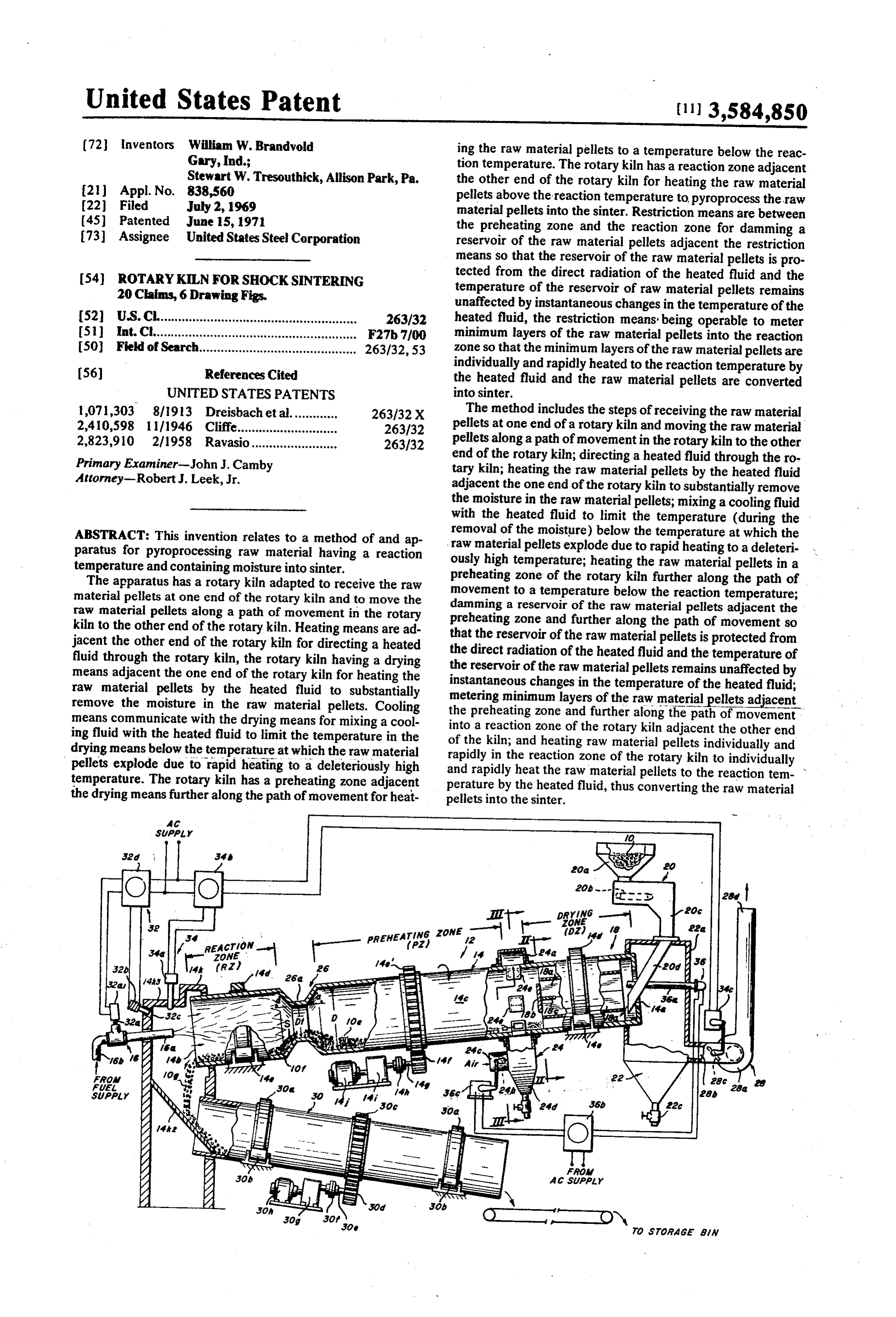
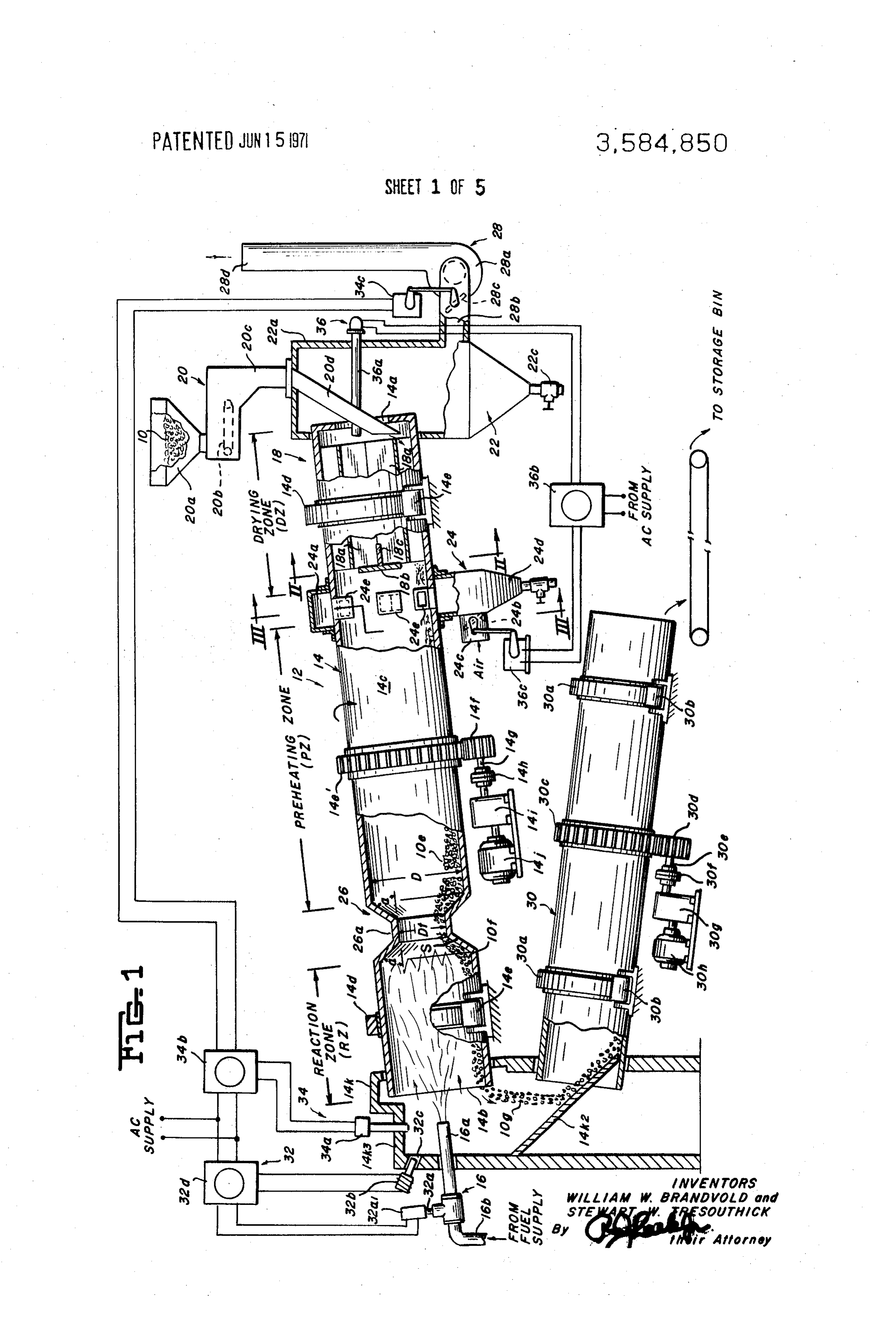
The aforesaid objects of this invention, and other objects paratus of this invention taken along the line - of FIGS. 2, 3 which will become apparent as the description proceeds, are in the direction of the arrows, achieved by providing a method of and apparatus for FIG. 2 is a sectional view taken along the line II-II of FIG. 1 pyroprocessing raw material having a reaction temperature in the direction of the arrows showing the baffle and the parti and containing moisture into sinter. 40 tions in the drying means of the apparatus, The apparatus has a rotary kiln adapted to receive the raw FIG. 3 is a sectional view taken along the line III-III of FIG. 1 in the direction of the arrows showing the inlet members, the material pellets at one end of the rotary kiln and to move the shroud raw material pellets along a path of movement in the rotary members and the control member in the cooling means kiln to the other end of the rotary kiln. Heating means are ad of the apparatus,
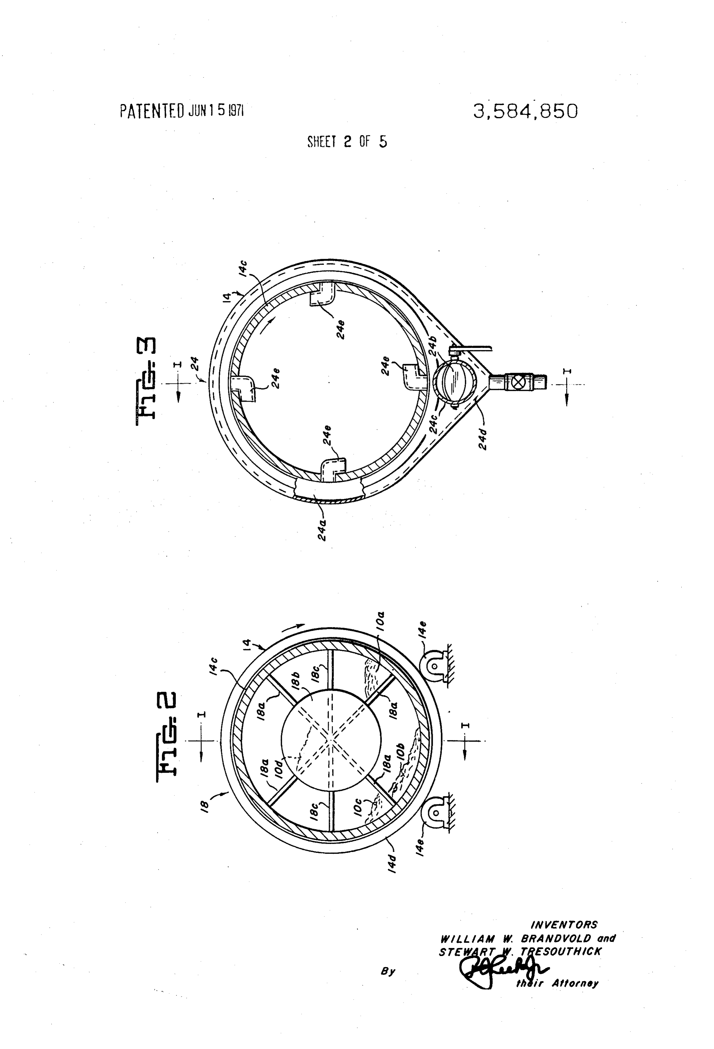
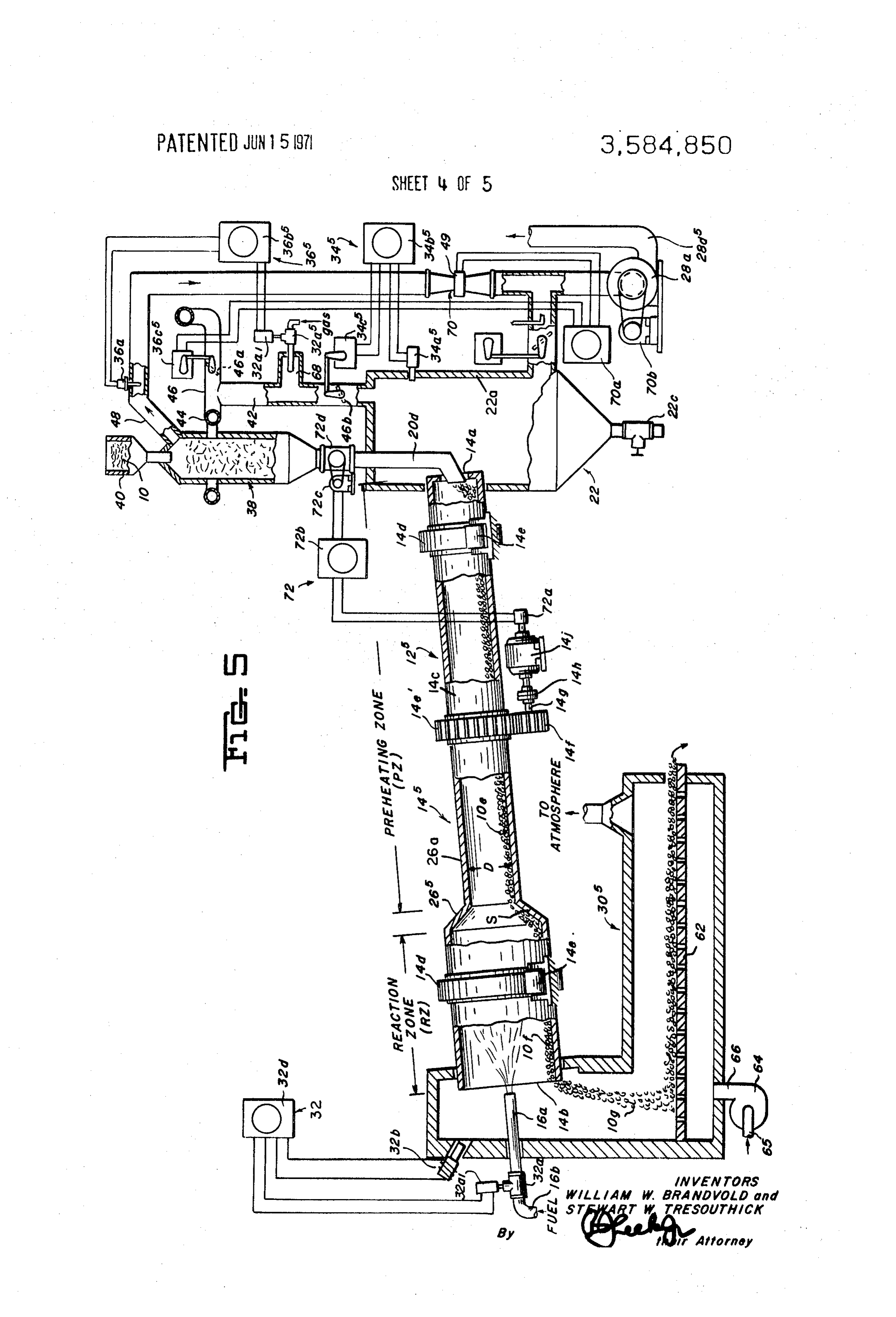
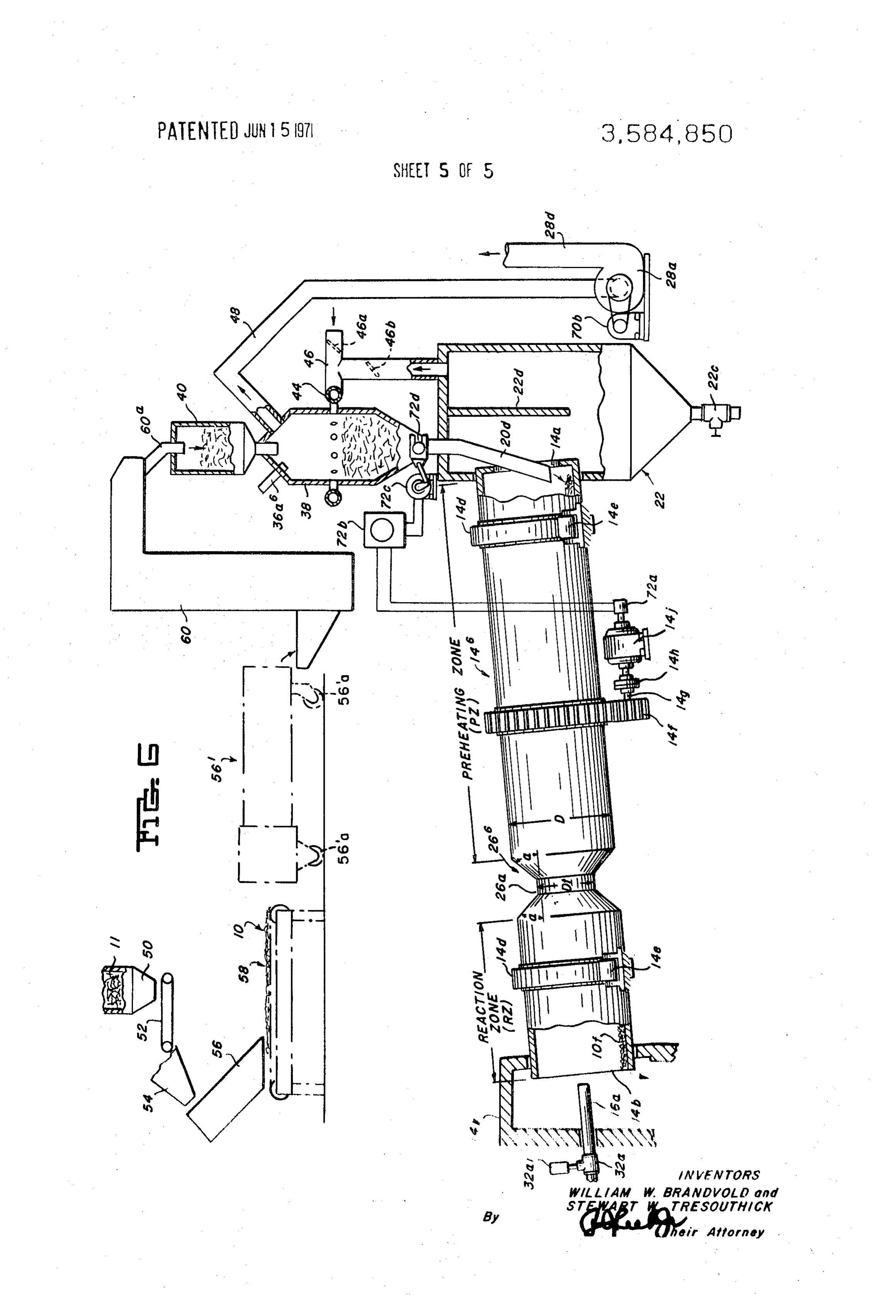
FIG. 4 is a view similar to FIG. 1 of an alternative embodi jacent the other end of the rotary kiln for directing a heated 45 ment fluid through the rotary kiln, the rotary kiln having a drying mentsofofthe apparatus and eliminating for clarity certain ele means adjacent the one end of the rotary kiln for heating the means arethe control means for the apparatus which control raw material pellets by the heated fluid to substantially FIG. 1, essentially the same as the control means shown in remove the moisture in the raw material pellets. Cooling FIG. 5 is a view similar to FIG. 1 of a further alternative em means communicate with the drying means for mixing a cool 50 bodiment of the apparatus, showing an external drying means ing fluid with the heated fluid to limit the temperature in the and the associated control means, and drying means below the temperature at which the raw material FIG. 6 is a view similar to FIGS. 1, 4, 5 showing raw material pellets explode due to rapid heating to a deleteriously high pellet producing means.
temperature. The rotary kiln has a preheating zone adjacent Although the principles of this invention are broadly ap the drying means further along the path of movement for heat 55 plicable to the pyroprocessing of raw material pellets into ing the raw material pellets to a temperature below the reac tion temperature. The rotary kiln has a reaction zone adjacent sinter, this invention is particularly adapted for use in conjunc the other end of the rotary kiln for heating the raw material tion with the pyroprocessing of portland cement, calcium alu pellets above the reaction temperature to pyroprocess the raw 60 products cement, minate light weight aggregates and indurated into sinter, and hence it has been so illustrated and material pellets into the sinter. Restriction means are between the preheating zone and the reaction zone for damming a will be so described.
reservoir of the raw material pellets adjacent the restriction DETAILED DESCRIPTION means so that the reservoir of the raw material pellets is pro tected from the direct radiation of the heated fluid and the 65 With specific reference to the form of this invention illus temperature of said reservoir of raw material pellets remains trated in the drawings, and referring particularly to FIG. 1, an unaffected by instantaneous changes in the temperature of the apparatus for pyroprocessing raw material pellets 10 having a heated fluid, the restriction means being operable to meter reaction temperature of about 2,200 F. to 3,000 F. and con minimum layers of the raw material pellets into the reaction taining moisture, is indicated generally by the reference nu zone so that the minimum layers of the raw material pellets are 70 meral 12.
individually and rapidly heated to the reaction temperature by Raw Material 10 the heated fluid and the raw material pellets are converted into sinter. The raw material 10 may comprise raw material for the The method includes the steps of receiving the raw material production of portland cement, or calcium aluminate cement, pellets at one end of a rotary kiln and moving the raw material 75 light weight aggregates, indurated products and mixtures hav
Page 9
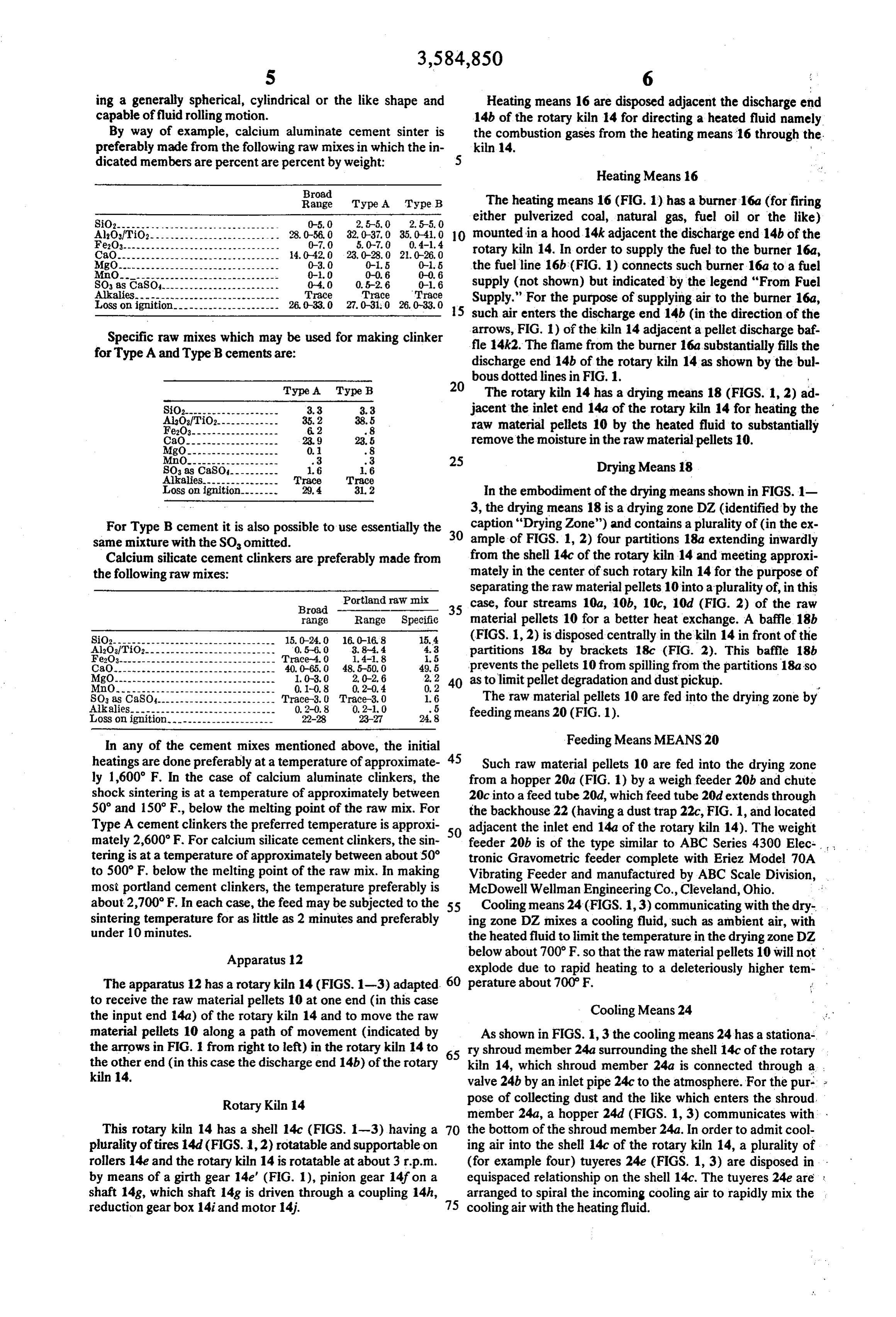
ing a generally spherical, cylindrical or the like shape and Heating means 16 are disposed adjacent the discharge end capable of fluid rolling motion. 14b of the rotary kiln 14 for directing a heated fluid namely By way of example, calcium aluminate cement sinter is the combustion gases from the heating means 16 through the preferably made from the following raw mixes in which the in kiln. 14.
dicated members are percent are percent by weight: 5
Heating Means 16
Broad
Range Type A Type B The heating means 16 (FIG. 1) has a burner 16a (for firing
SiO2------....... 2.5-5, O 2.5-50 either pulverized coal, natural gas, fuel oil or the like) AlOf TiO2------ 32. 0-37.0 35.0-4, 0 10 mounted in a hood 14k adjacent the discharge end 14b of the Fe2O3------- 5.0-7.0 0,4-1, 4
CO---------------------------------- 23,028.0 2.0-26.0 rotary kiln 14. In order to supply the fuel to the burner 16a,
the fuel line 16b (FIG. 1) connects such burner 16a to a fuel
SO as CaSO 0.5-2.6 0-1.6 supply (not shown) but indicated by the legend "From Fuel
Loss on ignitio
Trace Trace 26,0-330 27,030 26,033.0 Supply.' For the purpose of supplying air to the burner 16a, 15 such air enters the discharge end 14b (in the direction of the
Specific raw mixes which may be used for making clinker arrows, FIG. 1) of the kiln 14 adjacent a pellet discharge baf. for Type A and Type B cements are: fle 14k2. The flame from the burner 16a substantially fills the discharge end 14b of the rotary kiln 14 as shown by the bul bous dotted lines in FIG. 1. s
Type A. 20 The rotary kiln 14 has a drying means 18 (FIGS. 1, 2) ad
SiO2-------------------- jacent the inlet end 14a of the rotary kiln 14 for heating the
SOsas CaSOI
Loss on ignition.------- T
raw material pellets 10 by the heated fluid to substantially remove the moisture in the raw material pellets 10.
Drying Means 18
In the embodiment of the drying means shown in FIGS. 1 3, the drying means 18 is a drying zone DZ (identified by the
For Type B cement it is also possible to use essentially the caption "Drying Zone') and contains a plurality of (in the ex same mixture with the SO, omitted. 30 ample of FIGS. 1, 2) four partitions 18a extending inwardly Calcium silicate cement clinkers are preferably made from from the shell 14c of the rotary kiln 14 and meeting approxi the following raw mixes: mately in the center of such rotary kiln 14 for the purpose of Portland raw mix separating the raw material pellets 10 into a plurality of, in this
Broad - 35 case, four streams 10a, 10b, 10c, 10d (FIG. 2) of the raw range Range Specific material pellets 10 for a better heat exchange. A baffle 18b
SiO2---------------------------------- 15.0-240 160-168 15.4 (FIGS. 1, 2) is disposed centrally in the kiln 14 in front of the
partitions 18a by brackets 18c (FIG. 2). This baffle 18b
CaO. 40. 0-65, 0 48.5-50, 0 49.5 prevents the pellets 10 from spilling from the partitions 18a so MgO.
MnO,
0.2-0.4 40 as to limit pellet degradation and dust pickup.
0, 2 s
The raw material pellets 10 are fed into the drying zone by
LOSS on ignition.--------------------- 22-28 23-27 24.8 feeding means 20 (FIG. 1).
In any of the cement mixes mentioned above, the initial Feeding Means MEANS 20 heatings are done preferably at a temperature of approximate Such raw material pellets 10 are fed into the drying zone ly 1,600 F. In the case of calcium aluminate clinkers, the from a hopper 20a (FIG. 1) by a weigh feeder 20b and chute shock sintering is at a temperature of approximately between 20c into a feed tube 20d, which feed tube 20d extends through 50 and 150 F., below the melting point of the raw mix. For the backhouse 22 (having a dust trap 22c, FIG. 1, and located Type A cement clinkers the preferred temperature is approxi so adjacent the inlet end 14a of the rotary kiln 14). The weight mately 2,600 F. For calcium silicate cement clinkers, the sin feeder 20b is of the type similar to ABC Series 4300 Elec tering is at a temperature of approximately between about 50 tronic Gravometric feeder complete with Eriez Model 70A to 500 F. below the melting point of the raw mix. In making Vibrating Feeder and manufactured by ABC Scale Division, most portland cement clinkers, the temperature preferably is McDowell Wellman Engineering Co., Cleveland, Ohio.
about 2,700°F. In each case, the feed may be subjected to the 55 Cooling means 24 (FIGS. 1,3) communicating with the dry sintering temperature for as little as 2 minutes and preferably ing zone DZ. mixes a cooling fluid, such as ambient air, with under 10 minutes. the heated fluid to limit the temperature in the drying zone DZ Apparatus 12 below about 700°F. so that the raw material pellets 10 will not explode due to rapid heating to a deleteriously higher tem
The apparatus 12 has a rotary kiln 14 (FIGS. 1-3) adapted 60 perature about 700°F.
to receive the raw material pellets 10 at one end (in this case Cooling Means 24 the input end 14a) of the rotary kiln 14 and to move the raw material pellets 10 along a path of movement (indicated by As shown in FIGS. 1, 3 the cooling means 24 has a stationa the arrows in FIG. 1 from right to left) in the rotary kiln 14 to is ry shroud member 24a surrounding the shell 14c of the rotary the other end (in this case the discharge end 14b) of the rotary kiln 14, which shroud member 24a is connected through a . kiln 14. valve 24b by an inlet pipe 24c to the atmosphere. For the pur. Rotary Kiln 14 pose of collecting dust and the like which enters the shroud member 24a, a hopper 24d (FIGS. 1, 3) communicates with
This rotary kiln 14 has a shell 14c (FIGS. 1-3) having a 70 the bottom of the shroud member 24a. In order to admit cool plurality of tires 14d (FIGS. 1,2) rotatable and supportable on ing air into the shell 14c of the rotary kiln 14, a plurality of rollers 14e and the rotary kiln 14 is rotatable at about 3 r.p.m. (for example four) tuyeres 24e (FIGS. 1, 3) are disposed in by means of a girth gear 14e' (FIG. 1), pinion gear 14f on a equispaced relationship on the shell 14c. The tuyeres 24e are : shaft 14g, which shaft 14g is driven through a coupling 14h, arranged to spiral the incoming cooling air to rapidly mix the reduction gearbox 14i and motor 14. 75 cooling air with the heating fluid.
Page 10
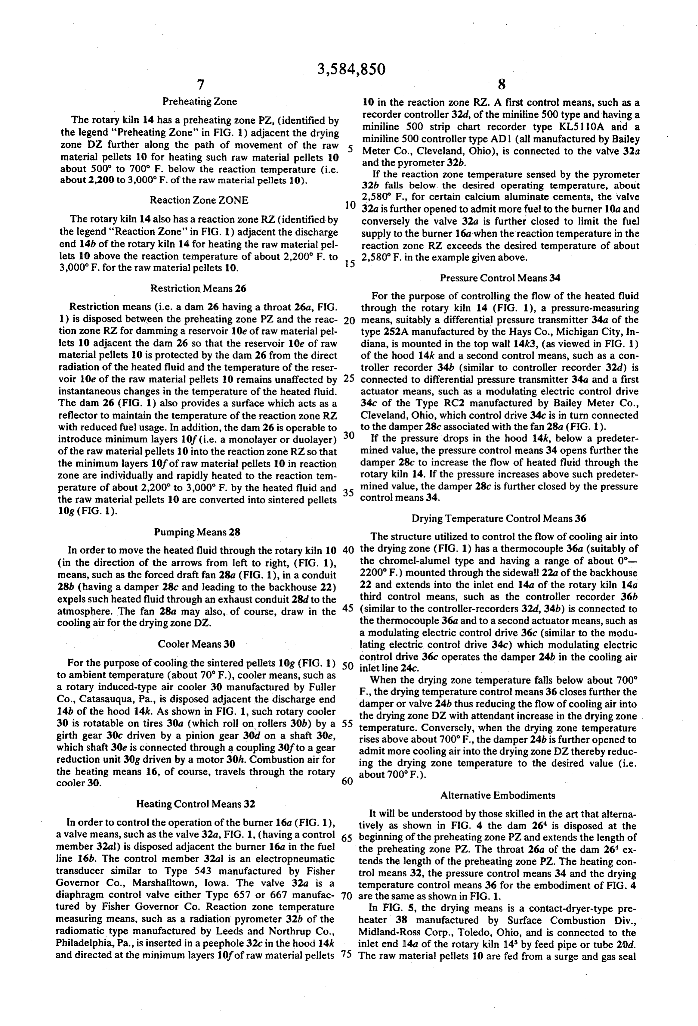
Preheating Zone 10 in the reaction zone RZ. A first control means, such as a The rotary kiln 14 has a preheating zone PZ, (identified by recorder controller 32d, of the miniline 500 type and having a the legend "Preheating Zone" in FIG. 1) adjacent the drying miniline 500 strip chart recorder type KL51 10A and a zone DZ further along the path of movement of the raw miniline 500 controller type AD 1 (all manufactured by Bailey material pellets 10 for heating such raw material pellets 10 Meter Co., Cleveland, Ohio), is connected to the valve 32a about 500 to 700° F. below the reaction temperature (i.e. and the pyrometer 32b.
about 2,200 to 3,000 F. of the raw material pellets 10). If the reaction zone temperature sensed by the pyrometer 32b falls below the desired operating temperature, about
Reaction Zone ZONE 2,580 F., for certain calcium aluminate cements, the valve 10 32a is further opened to admit more fuel to the burner 10a and
The rotary kiln 14 also has a reaction zone RZ (identified byconversely the valve 32a is further closed to limit the fuel the legend "Reaction Zone" in FIG. 1) adjacent the discharge supply to the burner 16a when the reaction temperature in the end 14b of the rotary kiln 14 for heating the raw material pel reaction zone RZ exceeds the desired temperature of about lets 10 above the reaction temperature of about 2,200 F. to 15 2,580 F. in the example given above.
3,000 F. for the raw material pellets 10.
Pressure Control Means 34
Restriction Means 26
For the purpose of controlling the flow of the heated fluid
Restriction means (i.e. a dam 26 having a throat 26a, FIG. through the rotary kiln 14 (FIG. 1), a pressure-measuring 1) is disposed between the preheating zone PZ and the reac 20 means, suitably a differential pressure transmitter 34a of the tion zone RZ for damming a reservoir 10e of raw material pel type 252A manufactured by the Hays Co., Michigan City, In lets 10 adjacent the dam 26 so that the reservoir 10e of raw diana, is mounted in the top wall 14 k3, (as viewed in FIG. 1) material pellets 10 is protected by the dam 26 from the direct of the hood 14k and a second control means, such as a con radiation of the heated fluid and the temperature of the reser troller recorder 34b (similar to controller recorder 32d) is voir 10e of the raw material pellets 10 remains unaffected by 25 connected to differential pressure transmitter 34a and a first instantaneous changes in the temperature of the heated fluid. actuator means, such as a modulating electric control drive The dam 26 (FIG. 1) also provides a surface which acts as a 34c of the Type RC2 manufactured by Bailey Meter Co., reflector to maintain the temperature of the reaction zone RZ Cleveland, Ohio, which control drive 34c is in turn connected with reduced fuel usage. In addition, the dam 26 is operable to 30 to the damper 28c associated with the fan 28a (FIG. 1). introduce minimum layers 10f (i.e. a monolayer or duolayer) If the pressure drops in the hood 14k, below a predeter of the raw material pellets 10 into the reaction zone RZso that mined value, the pressure control means 34 opens further the the minimum layers 10f of raw material pellets 10 in reaction damper 28c to increase the flow of heated fluid through the zone are individually and rapidly heated to the reaction tem rotary kiln 14. If the pressure increases above such predeter perature of about 2,200 to 3,000 F. by the heated fluid and 35 mined value, the damper 28c is further closed by the pressure the raw material pellets 10 are converted into sintered pellets control means 34.
10g (FIG. 1). Drying Temperature Control Means 36 Pumping Means 28 The structure utilized to control the flow of cooling air into In order to move the heated fluid through the rotary kiln 10 40 the drying zone (FIG. 1) has a thermocouple 36a (suitably of (in the direction of the arrows from left to right, (FIG. 1), the chromel-alumel type and having a range of about 0° means, such as the forced draft fan 28a (FIG. 1), in a conduit 2200 F.) mounted through the sidewall 22a of the backhouse 28b (having a damper 28c and leading to the backhouse 22) 22 and extends into the inlet end 14a of the rotary kiln 14a expels such heated fluid through an exhaust conduit 28d to the 45 third control means, such as the controller recorder 36b atmosphere. The fan 28a may also, of course, draw in the (similar to the controller-recorders 32d, 34b) is connected to cooling air for the drying zone DZ. the thermocouple 36a and to a second actuator means, such as a modulating electric control drive 36c (similar to the modu
Cooler Means 30 lating electric control drive 34c) which modulating electric For the purpose of cooling the sintered pellets 10g (FIG. 1) 50 inlet linedrive control
36c operates the damper 24b in the cooling air to ambient temperature (about 70 F.), cooler means, such as When the drying zone temperature falls below about 700 a rotary induced-type air cooler 30 manufactured by Fuller F., the drying temperature control means 36 closes further the Co., Catasauqua, Pa., is disposed adjacent the discharge end damperor valve 24b thus reducing the flow of cooling air into 14b of the hood 14k. As shown in FIG. 1, such rotary cooler the drying zone DZ with attendant increase in the drying zone 30 is rotatable on tires 30a (which roll on rollers 30b) by a 55 temperature. Conversely, when the drying zone temperature girth gear 30c driven by a pinion gear 30d on a shaft 30e, rises above about 700°F., the damper 24b is further opened to which shaft 30e is connected through a coupling 30f to a gear admit more cooling air into the drying zone DZ thereby reduc reduction unit 30g driven by a motor 30h. Combustion air for ing the drying zone temperature to the desired value (i.e. the heating means 16, of course, travels through the rotary about 700°F.).
cooler 30. 60
Alternative Embodiments
Heating Control Means 32
It will be understood by those skilled in the art that alterna
In order to control the operation of the burner 16a (FIG. 1), tively as shown in FIG. 4 the dam 26 is disposed at the a valve means, such as the valve 32a, FIG. 1, (having a control 65 beginning of the preheating zone PZ and extends the length of member 32al) is disposed adjacent the burner 16a in the fuel the preheating zone PZ. The throat 26a of the dam 26 ex line 16b. The control member 32al is an electropneumatic tends the length of the preheating zone PZ. The heating con transducer similar to Type 543 manufactured by Fisher trol means 32, the pressure control means 34 and the drying Governor Co., Marshalltown, Iowa. The valve 32a is a temperature control means 36 for the embodiment of FIG. 4 diaphragm control valve either Type 657 or 667 manufac 70 are the same as shown in FIG. 1.
tured by Fisher Governor Co. Reaction zone temperature In FIG. 5, the drying means is a contact-dryer-type pre measuring means, such as a radiation pyrometer 32b of the heater 38 manufactured by Surface Combustion Div., radiomatic type manufactured by Leeds and Northrup Co., Midland-Ross Corp., Toledo, Ohio, and is connected to the Philadelphia, Pa., is inserted in a peephole 32c in the hood 14k inlet end 14a of the rotary kiln 14 by feed pipe or tube 20d. and directed at the minimum layers 10f of raw material pellets 75 The raw material pellets 10 are fed from a surge and gas seal
Page 11
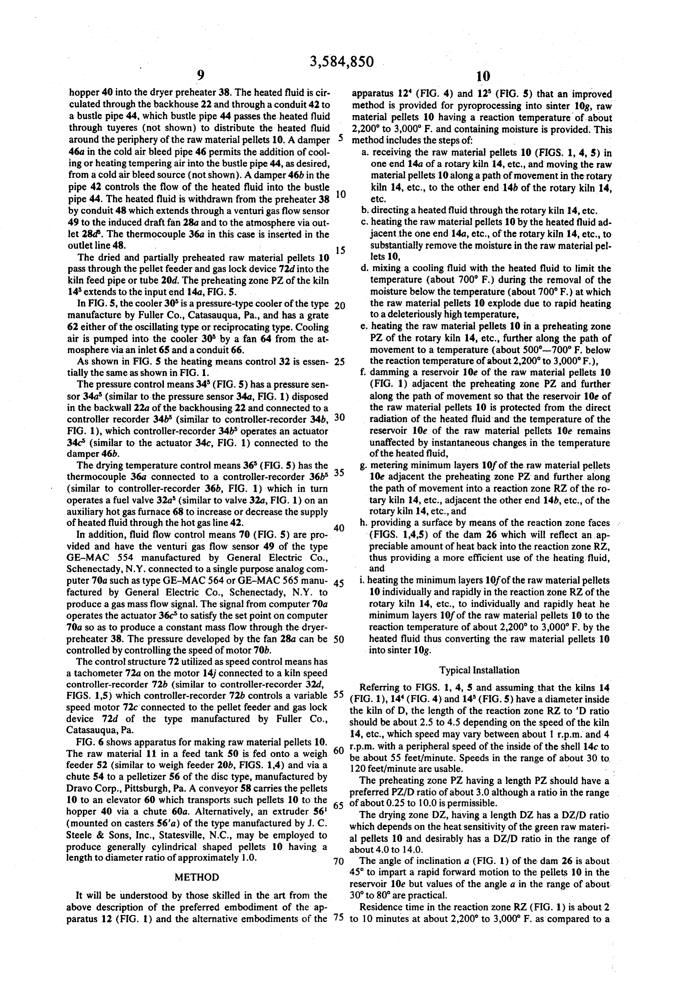
hopper 40 into the dryer preheater 38. The heated fluid is cir apparatus 12 (FIG. 4) and 12 (FIG. 5) that an improved culated through the backhouse 22 and through a conduit 42 to method is provided for pyroprocessing into sinter 10g, raw a bustle pipe 44, which bustle pipe 44 passes the heated fluid material pellets 10 having a reaction temperature of about through tuyeres (not shown) to distribute the heated fluid 2,200 to 3,000 F. and containing moisture is provided. This around the periphery of the raw material pellets 10. A damper 5 method includes the steps of:
46a in the cold air bleed pipe 46 permits the addition of cool a. receiving the raw material pellets 10 (FIGS. 1, 4, 5) in ing or heating tempering air into the bustle pipe 44, as desired, one end 14a of a rotary kiln 14, etc., and moving the raw from a cold air bleed source (not shown). A damper 46b in the material pellets 10 along a path of movement in the rotary pipe 42 controls the flow of the heated fluid into the bustle O kiln 14, etc., to the other end 14b of the rotary kiln 14, pipe 44. The heated fluid is withdrawn from the preheater 38 etc.
by conduit 48 which extends through a venturigas flow sensor b, directing a heated fluid through the rotary kiln 14, etc. 49 to the induced draft fan 28a and to the atmosphere via out c. heating the raw material pellets 10 by the heated fluid ad let 28d. The thermocouple 36a in this case is inserted in the jacent the one end 14a, etc., of the rotary kiln 14, etc., to outlet line 48. 5 substantially remove the moisture in the raw material pel The dried and partially preheated raw material pellets 10 lets 10, pass through the pellet feeder and gas lock device 72d into the d. mixing a cooling fluid with the heated fluid to limit the kiln feed pipe or tube 20d. The preheating zone PZ of the kiln temperature (about 700 F) during the removal of the 14 extends to the input end 14a, FIG. 5. moisture below the temperature (about 700°F.) at which In FIG. 5, the cooler 30 is a pressure-type cooler of the type the raw material pellets 10 explode due to rapid heating manufacture by Fuller Co., Catasauqua, Pa., and has a grate to a deleteriously high temperature, 62 either of the oscillating type or reciprocating type. Cooling e. heating the raw material pellets 10 in a preheating zone air is pumped into the cooler 30 by a fan 64 from the at PZ of the rotary kiln 14, etc., further along the path of mosphere via an inlet 65 and a conduit 66. movement to a temperature (about 500-700°F. below As shown in FIG. S the heating means control 32 is essen 25 the reaction temperature of about 2,200 to 3,000F.), tially the same as shown in FIG. 1. f damming a reservoir 10e of the raw material pellets 10 The pressure control means 34 (FIG.S) has a pressure sen (FIG. 1) adjacent the preheating zone PZ and further sor 34a (similar to the pressure sensor 34a, FIG. 1) disposed along the path of movement so that the reservoir 10e of in the backwall 22a of the backhousing 22 and connected to a the raw material pellets 10 is protected from the direct controller recorder 34b (similar to controller-recorder 34b, 30 radiation of the heated fluid and the temperature of the FIG. 1), which controller-recorder 34b operates an actuator reservoir 10e of the raw material pellets 10e remains 34c (similar to the actuator 34c, FIG. 1) connected to the unaffected by instantaneous changes in the temperature damper 46b. of the heated fluid,
The drying temperature control means 36 (FIG. 5) has the 35 g. metering minimum layers 10f of the raw material pellets thermocouple 36a connected to a controller-recorder 36b 10e adjacent the preheating zone PZ and further along (similar to controller-recorder 36b, FIG. 1) which in turn the path of movement into a reaction zone RZ of the ro operates a fuel valve 32a (similar to valve 32a, FIG. 1) on an tary kiln 14, etc., adjacent the other end 14b, etc., of the auxiliary hot gas furnace 68 to increase or decrease the supply rotary kiln 14, etc., and of heated fluid through the hot gas line 42. 40 h. providing a surface by means of the reaction zone faces In addition, fluid flow control means 70 (FIG. 5) are pro (FIGS. 1,4,5) of the dam 26 which will reflect an ap vided and have the venturi gas flow sensor 49 of the type preciable amount of heat back into the reaction zone RZ, GE-MAC 554 manufactured by General Electric Co., thus providing a more efficient use of the heating fluid, Schenectady, N.Y. connected to a single purpose analog com and puter 70a such as type GE-MAC 564 or GE-MAC 565 manu 45 i. heating the minimum layers 10fof the raw material pellets factured by General Electric Co., Schenectady, N.Y. to 10 individually and rapidly in the reaction zone RZ of the produce a gas mass flow signal. The signal from computer 70a rotary kiln 14, etc., to individually and rapidly heat he operates the actuator 36c to satisfy the set point on computer minimum layers 10f of the raw material pellets 10 to the 70a so as to produce a constant mass flow through the dryer reaction temperature of about 2,200 to 3,000 F. by the preheater 38. The pressure developed by the fan 28a can be 50 heated fluid thus converting the raw material pellets 10 controlled by controlling the speed of motor 70b. into sinter 10g.
The control structure 72 utilized as speed control means has a tachometer 72a on the motor 14.j connected to a kiln speed Typical Installation controller-recorder 72b (similar to controller-recorder 32d, Referring to FIGS. 1, 4, 5 and assuming that the kilns 14 FIGS. 15) which controller-recorder 72b controls a variable 55 (FIG. 1), 14 (FIG. 4) and 14 (FIG.5) have a diameter inside speed motor 72c connected to the pellet feeder and gas lock the kiln of D, the length of the reaction zone RZ to D ratio device 72d of the type manufactured by Fuller Co., should be about 2.5 to 4.5 depending on the speed of the kiln Catasauqua, Pa. 14, etc., which speed may vary between about 1 r.p.m. and 4 FIG. 6 shows apparatus for making raw material pellets 10. 60 r.p.m. with a peripheral speed of the inside of the shell 14c to The raw material 11 in a feed tank 50 is fed onto a weigh be about 55 feet/minute. Speeds in the range of about 30 to feeder 52 (similar to weigh feeder 20b, FIGS. 14) and via a 120 feet/minute are usable.
chute 54 to a pelletizer 56 of the disc type, manufactured by The preheating zone PZ having a length PZ should have a Dravo Corp., Pittsburgh, Pa. A conveyor 58 carries the pellets preferred PZ/D ratio of about 3.0 although a ratio in the range 10 to an elevator 60 which transports such pellets 10 to the of about 0.25 to 10.0 is permissible.
hopper 40 via a chute 60a. Alternatively, an extruder 56 65 The drying zone DZ, having a length DZ has a DZ/D ratio (mounted on casters S6'a) of the type manufactured by J. C. which depends on the heat sensitivity of the green raw materi Steele & Sons, Inc., Statesville, N.C., may be employed to al pellets 10 and desirably has a DZ/D ratio in the range of produce generally cylindrical shaped pellets 10 having a about 4.0 to 14.0.
length to diameter ratio of approximately 1.0. 70 The angle of inclination a (FIG. 1) of the dam 26 is about METHOD 45 to impart a rapid forward motion to the pellets 10 in the reservoir 10e but values of the angle a in the range of about
It will be understood by those skilled in the art from the 30 to 80 are practical.
above description of the preferred embodiment of the ap Residence time in the reaction zone RZ (FIG. 1) is about 2 paratus 12 (FIG. 1) and the alternative embodiments of the 75 to 10 minutes at about 2,200 to 3,000 F. as compared to a
Page 12
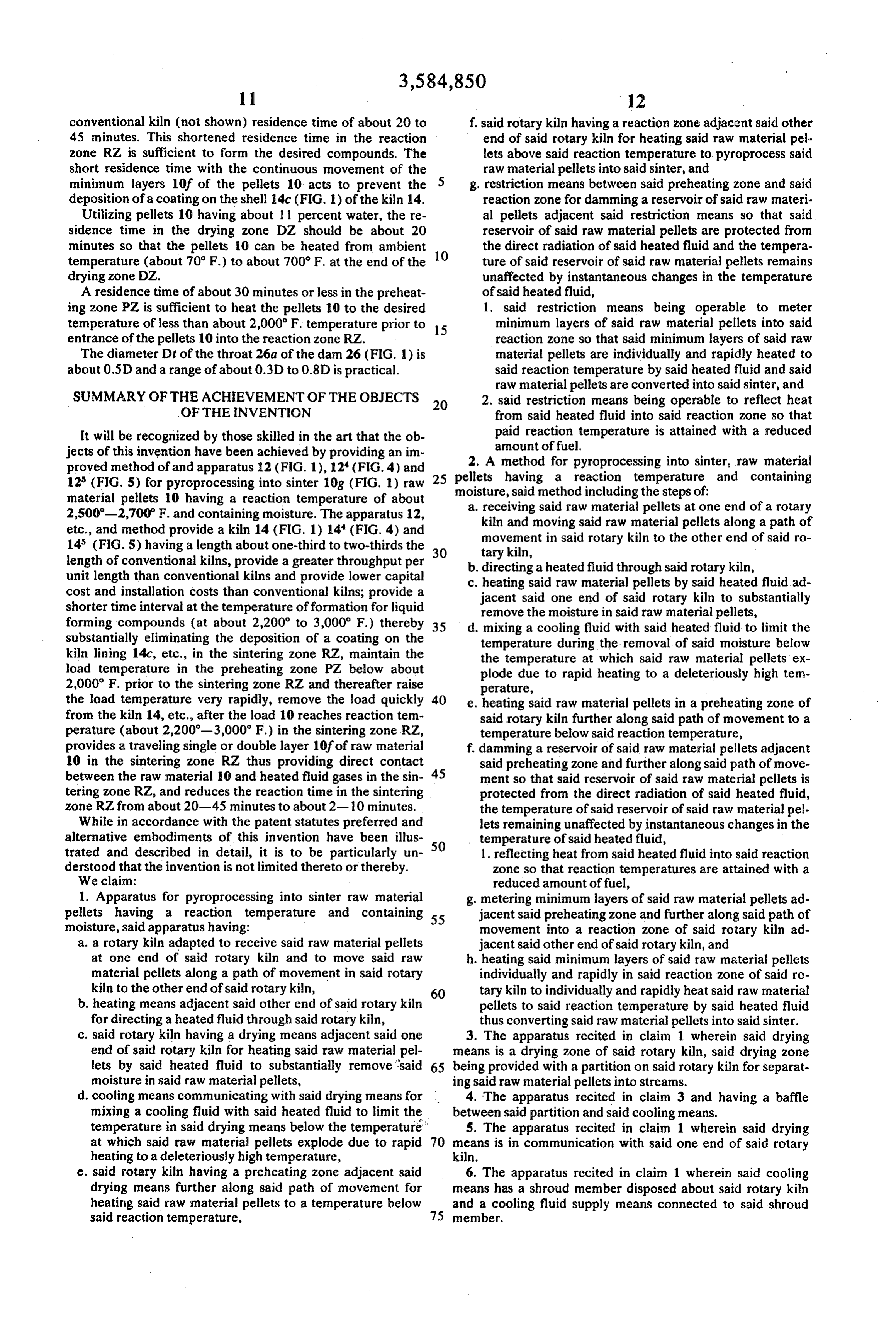
conventional kiln (not shown) residence time of about 20 to f, said rotary kiln having a reaction zone adjacent said other 45 minutes. This shortened residence time in the reaction end of said rotary kiln for heating said raw material pel zone RZ is sufficient to form the desired compounds. The lets above said reaction temperature to pyroprocess said short residence time with the continuous movement of the raw material pellets into said sinter, and minimum layers 10f of the pellets 10 acts to prevent the 5 g, restriction means between said preheating zone and said deposition of a coating on the shell 4c (FIG. I.) of the kiln 14. reaction zone for damming a reservoir of said raw materi Utilizing pellets 10 having about 11 percent water, the re al pellets adjacent said restriction means so that said sidence time in the drying zone DZ should be about 20 reservoir of said raw material pellets are protected from minutes so that the pellets 10 can be heated from ambient the direct radiation of said heated fluid and the tempera temperature (about 70 F.) to about 700 F. at the end of the 10 ture of said reservoir of said raw material pellets remains drying zone DZ. unaffected by instantaneous changes in the temperature A residence time of about 30 minutes or less in the preheat of said heated fluid, ing zone PZ is sufficient to heat the pellets 10 to the desired 1. said restriction means being operable to meter temperature of less than about 2,000 F. temperature prior to 15 minimum layers of said raw material pellets into said entrance of the pellets 10 into the reaction zone RZ. reaction zone so that said minimum layers of said raw The diameter Dt of the throat 26a of the dam 26 (FIG. 1) is material pellets are individually and rapidly heated to about 0.5D and a range of about 0.3D to 0.8D is practical. said reaction temperature by said heated fluid and said
SUMMARY OF THE ACHIEVEMENT OF THE OBJECTS 20
raw material pellets are converted into said sinter, and 2. said restriction means being operable to reflect heat
OF THE INVENTION from said heated fluid into said reaction zone so that It will be recognized by those skilled in the art that the ob paid reaction temperature is attained with a reduced jects of this invention have been achieved by providing an im amount of fuel.
2. A method for pyroprocessing into sinter, raw material proved method of and apparatus 12 (FIG. 1), 2 (FIG. 4) and 25 pellets 12 (FIG. 5) for pyroprocessing into sinter 10g (FIG. 1) raw having a reaction temperature and containing material pellets 10 having a reaction temperature of about moisture, said method including the steps of: 2,500-2,700F. and containing moisture. The apparatus 12, a. receiving said raw material pellets at one end of a rotary etc., and method provide a kiln 14 (FIG. 1) 14 (FIG. 4) and kiln and moving said raw material pellets along a path of 14 (FIG.S) having a length about one-third to two-thirds the 30 movement in said rotary kiln to the other end of said ro length of conventional kilns, provide a greater throughput per tary kiln, unit length than conventional kilns and provide lower capital b. directing a heated fluid through said rotary kiln, cost and installation costs than conventional kilns; provide a c. heating said raw material pellets by said heated fluid ad jacent said one end of said rotary kiln to substantially shorter time interval at the temperature of formation for liquid forming compounds (at about 2,200 to 3,000 F.) thereby 35 d. remove the moisture in said raw material pellets, mixing a cooling fluid with said heated fluid to limit the substantially eliminating the deposition of a coating on the temperature during the removal of said moisture below kiln lining 14c, etc., in the sintering zone RZ, maintain the the temperature at which said raw material pellets ex load temperature in the preheating zone PZ below about plode due to rapid heating to a deleteriously high tem 2,000 F. prior to the sintering zone RZ and thereafter raise perature, the load temperature very rapidly, remove the load quickly 40 e. heating said raw material pellets in a preheating zone of from the kiln 14, etc., after the load 10 reaches reaction tem said rotary kiln further along said path of movement to a perature (about 2,200-3,000 F.) in the sintering zone RZ, temperature below said reaction temperature, provides a traveling single or double layer 10f of raw material f. damming a reservoir of said raw material pellets adjacent 10 in the sintering zone RZ thus providing direct contact said preheating zone and further along said path of move between the raw material 10 and heated fluid gases in the sin 45 ment so that said reservoir of said raw material pellets is tering zone RZ, and reduces the reaction time in the sintering protected from the direct radiation of said heated fluid, zone RZ from about 20-45 minutes to about 2-10 minutes. the temperature of said reservoir of said raw material pel While in accordance with the patent statutes preferred and lets remaining unaffected by instantaneous changes in the alternative embodiments of this invention have been illus temperature of said heated fluid, trated and described in detail, it is to be particularly un 50 1. reflecting heat from said heated fluid into said reaction derstood that the invention is not limited thereto or thereby. Zone so that reaction temperatures are attained with a We claim: reduced amount of fuel, 1. Apparatus for pyroprocessing into sinter raw material g. metering minimum layers of said raw material pellets ad pellets having a reaction temperature and containing 55 jacent said preheating zone and further along said path of moisture, said apparatus having: movement into a reaction zone of said rotary kiln ad a. a rotary kiln adapted to receive said raw material pellets jacent said other end of said rotary kiln, and at one end of said rotary kiln and to move said raw h. heating said minimum layers of said raw material pellets material pellets along a path of movement in said rotary individually and rapidly in said reaction zone of said ro kiln to the other end of said rotary kiln, 60 tary kiln to individually and rapidly heat said raw material b. heating means adjacent said other end of said rotary kiln pellets to said reaction temperature by said heated fluid for directing a heated fluid through said rotary kiln, thus converting said raw material pellets into said sinter. c. said rotary kiln having a drying means adjacent said one 3. The apparatus recited in claim 1 wherein said drying end of said rotary kiln for heating said raw material pel means is a drying zone of said rotary kiln, said drying zone lets by said heated fluid to substantially remove said 65 being provided with a partition on said rotary kiln for separat moisture in said raw material pellets, ing said raw material pellets into streams. d. cooling means communicating with said drying means for 4. The apparatus recited in claim 3 and having a baffle mixing a cooling fluid with said heated fluid to limit the between said partition and said cooling means. temperature in said drying means below the temperature 5. The apparatus recited in claim 1 wherein said drying at which said raw material pellets explode due to rapid means is in communication with said one end of said rotary heating to a deleteriously high temperature, kiln.
e. said rotary kiln having a preheating zone adjacent said 6. The apparatus recited in claim 1 wherein said cooling drying means further along said path of movement for means has a shroud member disposed about said rotary kiln heating said raw material pellets to a temperature below and a cooling fluid supply means connected to said shroud said reaction temperature, 75 member.
Page 13
7. The apparatus recited in claim 6 wherein said rotary kiln said raw material pellets by said heated fluid is performed in a carries an inlet member in communication with said shroud drying means which is in communication with said one end of member. said rotary kiln.
8. The apparatus recited in claim 1 and having pumping 15. The method recited in claim 2 and including the step of means in communication with said one end of said rotary kiln 5 separating said raw material pellets into streams while heating for moving said heated fluid through said rotary kiln.
9. The apparatus recited in claim 1 and having cooler means said raw material pellets by said heated fluid to substantially adjacent said other end of said rotary kiln for cooling said remove the moisture in saidraw material pellets. 16. The method recited in claim 2 and including the step of sinter.
10. The apparatus recited in claim 1 and having valve means O pumping said heated fluid through said rotary kiln. 17. The method recited in claim 2 and including the step of associated with said heating means, reaction zone temperature cooling said sinter.
measuring means adjacent said reaction zone for measuring said reaction zone temperature and a first control means con of: 18. The method recited in claim 2 and including the steps nected to said valve means and said reaction zone temperature measuring means for controlling said heating means. 15 a.measuring the reaction zone temperature, and 11. The apparatus recited in claim 8 and having pressure b. controlling the temperature of said heated fluid directed measuring means adjacent said other end of said rotary kiln, through said rotary kiln.
and a second control means connected to said pumping means 19. The method recited in claim 2 and including the steps and said pressure measuring means for controlling the flow of of:
said heated fluid through said rotary kiln. 20 a measuring the pressure adjacent said other end of said ro 12. The apparatus recited in claim 1 and having drying tem tary kiln, and perature measuring means associated with said drying means b. controlling the flow of said heated fluid through said ro and a third control means connected to said drying tempera tary kiln.
ture measuring means and said cooling means for controlling of:20. The method recited in claim 2 and including the steps the flow of said cooling fluid into said drying means. 25 13. The method recited in claim 2 wherein the heating of a.measuring the drying temperature, and said raw material pellets by said heated fluid is performed in a b. controlling the flow of said cooling fluid into said heated preheating zone of said rotary kiln. fluid.
14. The method recited in claim 2 wherein the heating of
Provenance
- Collection
- Cited prior art
- Original PDF
- patentimages.storage.googleapis.com →
- Filed
- 1969-07-02
- Pages
- 13
- Method
- pdftotext (the PDF's own text layer) + pdftoppm 300dpi page scans
- Source
- Google Patents bibliographic record
- Granted
- 1971-06-15
- Inventors
- William W Brandvold; Stewart W Tresouthick; United States Steel Corp
- Transcribed from
- patentimages.storage.googleapis.com →