patent · US5209786
Integrity-enhanced thermoelectrics
11 May 1993
Page 1 — bibliographic record
IIIHIIIHIIII USOO52097.86A
United States Patent (19) 11) Patent Number: 5,209,786 Rolfe et al. 45) Date of Patent: May 11, 1993 (54) INTEGRITY-ENHANCED FOREIGN PATENT DOCUMENTS
THERMOELECTRICS
75 Inventors: Jonathan L. Rolfe, North Easton; 0.122121 4/1984 European Pat. Off. ................ 35/32 John S. Beaty, Belmont, both of Primary Examiner-Peter A. Nelson
Mass. Attorney, Agent, or Firm-Lorusso & Loud 73) Assignee: Thermo Electron Technologies 57 ABSTRACT Corporation, Waltham, Mass. Disclosed are integrity-enhanced thermoelectric de (21) Appl. No.: 594,850 vices and methods of their preparation. Such devices (22 Filed: Oct. 9, 1990 have the following characteristics: (1) there is, on aver age, no greater than about 10% incidence of function 5ll Int. C. ............................................. H01, 35/28 loss (failure) of the device on application to the device 52 U.S. C. .................................... 136/211; 136/212; of a substantial impact or distortion force or corrosion 136/225; 136/232 exposure, and (2) the device have at least about 85% of 58) Field of Search ................ 136/211, 212, 225, 232 the thermal performance of thermoelectric devices (56) References Cited without integrity enhancement (i.e., thermal conductiv
ity across the integrity-enhanced devices is significantly less than 0.0021 Cal-Cm/Cm2 Sec "C., and is less than or 2,997,514 8/1961 Roeder .................................... 136/4 equal to about 0.0015 Cal-Cm/Cm2 Sec 'C.; empirically 3,713,899 1/1973 Sebestyen..... ... 136/233 expressed as maintenance of at least a 40' C. tempera 4,032,363 6/1977 Raag ................. ... 136/211 ture differential over the intra-plate distance which is 4,091,673 5/1978 Tamura et ... 75/351 about 3/16 to about of an inch.). Integrity enhance 4,419,023 12/1983 Hager, Jr. ... ... 374/179 ment techniques are described, including the method of 4,567,365 1/1986 Degenne .. ... 250/338 4,614,443 9/1986 Hamert ......... ... 374/63 embedding components of standard thermoelectric de 4,687,879 8/1987 Hendricks ... 136/212 vices in syntactic foam materials, such as those formed 4,907,060 3/1990 Nelson et al. 357/87 X of resins and balloon elements.
5,051,275 9/1991 Wong........... 357/72 X 5,057,903 10/1991 Olla ....................................... 357/72 13 Claims, 9 Drawing Sheets
Page 2
Drawing sheet — no readable text.
Page 3
Drawing sheet — no readable text.
Page 4
Drawing sheet — no readable text.
Page 5
Drawing sheet — no readable text.
Page 6
Drawing sheet — no readable text.
Page 7
Drawing sheet — no readable text.
Page 8
Drawing sheet — no readable text.
Page 9
Drawing sheet — no readable text.
Page 10
Drawing sheet — no readable text.
Page 11
ered) as a result of the metallized pads being dissolved
INTEGRITY-ENHANCED THERMOELECTRICS with the formation of replacement compounds on the dies.
FIELD OF THE INVENTION Efficiency of a thermoelectric device is limited by This invention is directed to integrity-enhanced ther heat "leakage" across the device nullifying or counter moelectric devices and methods of preparation thereof. acting the heat differential driving, or being established in particular, it concerns thermoelectric devices en by, the device. It is rarely possible to maintain a temper hanced to have the following characteristics: (1) there ature differential greater than about 65 or 70 C. across is, on average, no greater than about 10% incidence of the plates of a thermoelectric device. In multi-stage function loss (failure) of the device on application to the 10 thermoelectric devices, each successive stage will not device of a substantial impact or distortion force or produce such a large temperature differential, but the corrosion exposure, and (2) the devices have at least individual stages, if driven separately, will do so. about 85% of the thermal performance of thermoelec Embedding electrical devices in polymers and other tric devices without integrity enhancement. substances is known. However, the prior art, in general,
BACKGROUND OF THE INVENTION teaches the embedding of electrical devices only in materials which have relatively high thermal conduc
Thermoelectric devices for generating electric power tivity so as to be able to dissipate heat. Surprisingly, the from heat or for providing heating or cooling upon thermoelectric devices of the present invention, due to application of electricity are well known. Thermoelec the incorporation or embedding therein of syntactic tric devices are typically formed from an array of small 20 foam (providing "kinematic association' as described prisms or dies of alternating p-doped and n-doped bis muth telluride (BiTe), silicon-germanium alloy or other below) are superior as to shock resistance, yet have polycrystalline semiconductor materials connected in 15% whenasantointegrity-enhanced little loss increased heat leakage-less than about series by electrical connection (i.e., soldering) to metal near maximum and much less whendevice is driven at or driven below maxi lized pads bonded to thin ceramic plates (e.g., aluminum 25 mum. Moreover, the integrity-enhanced thermoelectric oxide or beryllium oxide plates about 1 mm thick). Sili con-germanium alloys are particularly useful at higher devicesIt is are resistant to corrosive attack.
an object of this invention to provide a thermo temperatures such as about the 600' C-1000' C. range. electric device resistant to impact, distortion and corro Thermoelectric devices are attractive in many appli cations because of their absence of moving parts, their 30 sion, yet having high thermal integrity. It is another object of this invention to provide an small size and low weight. Limitations on the use of such devices arise from their relative fragility and sus integrity-enhanced slew rate.
thermoelectric device with rapid ceptibility to degradation in particular chemical envi ronments, specifically corrosive environments. For SUMMARY OF THE INVENTION example, electrical connections in thermoelectric de 35 vices can fail as a result of mechanical or temperature This invention includes an integrity-enhanced ther shock or degradation as a result of the operating envi moelectric device. In particular embodiments the de ronment (e.g., corrosive chemicals). A single electrical vice comprises two or more dies or two or more stage connection failure can disable an entire thermoelectric units. In particular embodiments, such a device com device. A frequent source of failure is the differential prises at least two thermoelectric dies or thermocouples movement of the ceramic plates on impact or accelera (such as bismuth telluride), which are electrically con tion or bending. Stress from such movement or other nected at each of their respective ends to a conductive forces can result in failure at the solder joints or the pad bonded to a ceramic plate, and wherein the dies and nickel barrier layer. The nickel barrier layer is at each conductive pads are embedded in a syntactic foam in end of a die and to which solder bonds. The nickel 45 kinematic association. This type of device may include barrier layer prevents poisoning of the die with solder two or more stage units. The syntactic foam may com OS. prise a resin such as epoxies, polyurethane, urea-for Individual parts of thermoelectric devices may also maldhyde, silicone or fluorosilicone as well as hollow be fragile. The dies are brittle and prone to destruction glass spheres. Preferred glass spheres are from about 10 from vibration, flexure and other factors. Due to the to 250 in diameter. Plates of the device include alu variety of materials employed in the several compo mina ceramic plates. A preferred syntactic foam com nents of a thermoelectric device, different coefficients prises epoxy resin having glass balloons in a ratio of of expansion can cause bowing, fracture and ultimately about 70:30 (by weight).
failure. In particular embodiments thermoelectric de In a specific embodiment of the integrity-enhanced vices are built as multiple stage units having one ther 55 device thermal conductivity across the device is equal moelectric stage stacked upon another thermoelectric to or less than about 0.0010 Cal-Cm/Cm? Sec 'C., and stage to form a unitary thermoelectric device. Due to preferably equal to or less than about 0.0005 Cal size and temperature differentials, the multiple stage or Cm/Cm? Sec "C. Similarly, in a specific embodiment of stacked arrays are particularly prone to such damage. the integrity-enhanced device an empirical temperature In addition to failure, partial fracture can result in differential is equal to or greater than about 50' C., and exfoliation of particles which contaminate systems in preferably equal to or greater than about 60 C. which thermoelectric devices are installed. Another In particular embodiments of the invention there is, source of failure is operation of a device in a corrosive on average, no greater than about a 10% (and prefera or chemically destructive environment such as ferric bly no greater than about 5% and most preferably no chloride solution or salt spray etc. A conventional ther 65 greater than about 1%) incidence of function loss on moelectric device is exquisitely sensitive to corrosion impact of 30G (i.e., in testing a statistically significant by exposure to ferric chloride and will be destroyed in number of units), and preferably, no greater than about about eight hours (un-powered) or about 2 hours (pow a 10% (and preferably no greater than about 5% and
Page 12
most preferably no greater than about 1%) incidence of ther includes at least two of the couples electrically function loss on 3-axis random vibration of about 5 connected in series and having opposed ends connected minutes duration, of about 30 DB/octave, 0.04 G2/Hz to the plates. Such an embodiment may also comprise a from 20-2,000 Hz. syntactic foam of a vitreous material and/or sintered The invention includes integrity-enhanced thermo ceramic or glass micro-balloons and the resulting device electric devices having a slew rate of at least about 15" will be ultra-corrosion exposure resistant. Another par C./min, and preferably, a slew rate of at least about 40 ticular integrity-enhanced thermoelectric device of this C./min, and more preferably a slew rate of at least invention is:
about 40 C/20 sec. a first plate and a second plate spaced apart from each Embodiments of the invention include an integrity 10 other;
enhanced thermoelectric device having syntactic foam a couple including a p-doped leg and an n-doped leg, of a density equal to or less than about 0.88 gm/cc and and means for electrically interconnecting a first end of a rigidity of at least about 1 to 2 kg/meter/100 cm, and said p-doped leg to a first end of said n-doped leg; preferably, density equal to or less than about 0.44 means for connecting opposite ends of said p-doped gm/cc. 15 leg and of said n-doped leg to said plates; This invention further comprises a method of integ said plates and said legs defining an interspace be rity enhancing a thermoelectric device comprising em tween said plates; and, bedding in kinematic association said device in syntactic syntactic foam upon curing occupying said interspace foam to produce an integrity-enhanced thermoelectric device. The method includes embedding by injection of 20 with said legs and plates to form an embedded thermo syntactic foam under pressure, which in one embodi electric device, such that: as to the formed device; (i) there is, on average, no greater than about 10% ment is at a pressure of least about 5 psi. A convenient incidence of function loss (failure) of the device on viscosity of syntactic foam (prior to curing) for embed ding is from about 1,000 to about 20,000 Cps. In one impact or distortion force of acceleration forces of up to embodiment, the cured foam has a Shore hardness of at 25 about 20 G; or 3-axis random vibration of about 5 min least about Shore D45. The method results in a device utes, 30 DB/octave, 0.04 G2/Hz from 20-2,000 Hz; or wherein thermal conductivity across the resulting de bending forces in the 1-2 Kg/linear meter range; and, vice is equal to or less than about 0.0010 Cal-Cm/Cm2 than (ii) in an oxidizing or reducing environment (other Sec 'C., and preferably, equal to or less than about resin dissolving environment) sufficient to render 0.0005 Cal-Cm/Cm2 Sec 'C. Otherwise expressed, the 30 an unembedded device inoperative in hours or days, method results in a device wherein empirical tempera said embedded device operates in such an environment ture differential of the resulting thermoelectric device is at least 50 times longer than an unembedded device; equal to or greater than about 50° C., and preferably and, equal to or greater than about 60° C. In a particular (iii) the device has thermal conductivity across the embodiment the method results in a device comprising 35 device significantly less than 0.0021 Cal-Cm/Cm2 Sec at least two thermoelectric dies each end of which is *C. being about equal to or less than 0.0015 Cal electrically connected to a conductive pad bonded to a Cm/Cm2 Sec 'C.;
ceramic plate, wherein the dies and conductive pad are (iv) said syntactic foam comprises has not shrunk embedded in a syntactic foam in kinematic association. upon curing;
In specific embodiments, the method entails syntactic (v) said foam upon curing is associated or bonded foam with hollow glass spheres, preferably from about with said legs and plates to resist substantial impact or 10 to 250 in diameter. In particular, the method com distortion force while maintaining at least about 85% prises embedding a plurality of bismuth telluride ther thermal performance and said foam upon curing occu mocouples and alumina ceramic plates in syntactic foam pies at least a majority of the interspace; and, of epoxy resin and glass balloons said resin and balloons 45 wherein said foam before curing has a viscosity at in a ratio of about 70:30 (by weight). 65-70 F. (room or ambient temperature) of from about In a specific embodiment this invention includes an 2,000 to 20,000 Centipoise being readily flowable at integrity-enhanced thermoelectric device comprising: applied pressures of about 5 psi or greater. a first plate and a second plate spaced apart from each In a preferred embodiment, the syntactic foam com other; 50 prises a resin and glass balloons, the balloons being from a couple including a p-doped leg and an n-doped leg, about 45 to about 250 diameter and comprising about and means for electrically interconnecting a first end of (30%) by weight of the mixture of balloons and resin. said p-doped leg to a first end of said n-doped leg; The more preferred such devices have a slew rate of at means for connecting opposite ends of said p-doped least about 15 C/minute, and more preferably a slew leg and of said n-doped leg to said plates; 55 rate of at least about 40 C/minute, and still more pref. said plates and said legs defining an interspace be erably a slew rate of at least about 40 C./20 seconds, tween said plates; and, and yet more preferably a slew rate of at least about 40 syntactic foam occupying said interspace and in kine C/10 seconds.
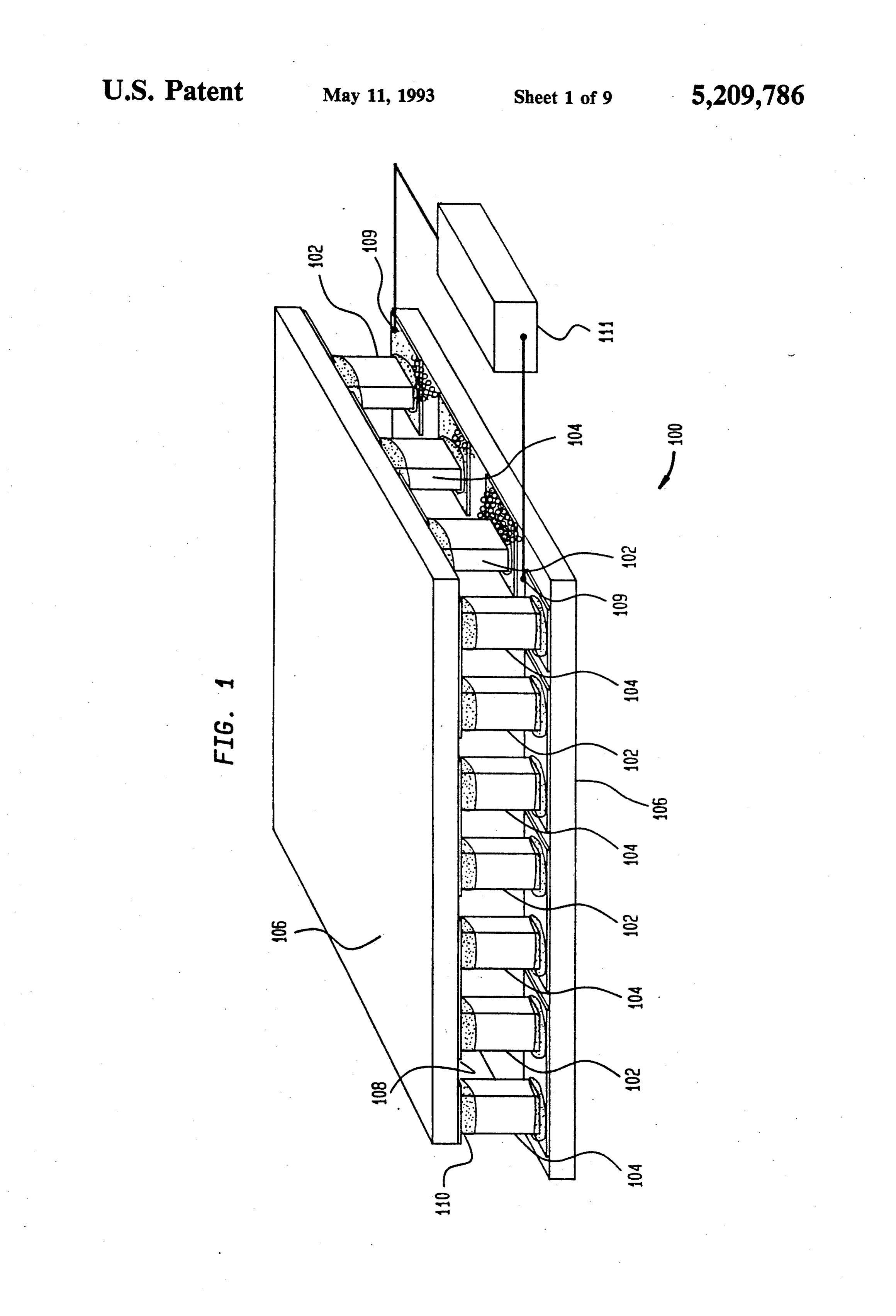
matic association with said legs and plates to form an BRIEF DESCRIPTION OF THE FIGURES embedded thermoelectric device. In a preferred em bodiment of this device the plates are formed of ceramic FIG. 1 is a diagrammatic representation in perspec material and the means for electrically connecting a tive of a type of thermoelectric device currently avail p-doped leg to an n-doped leg includes a metal pad able.
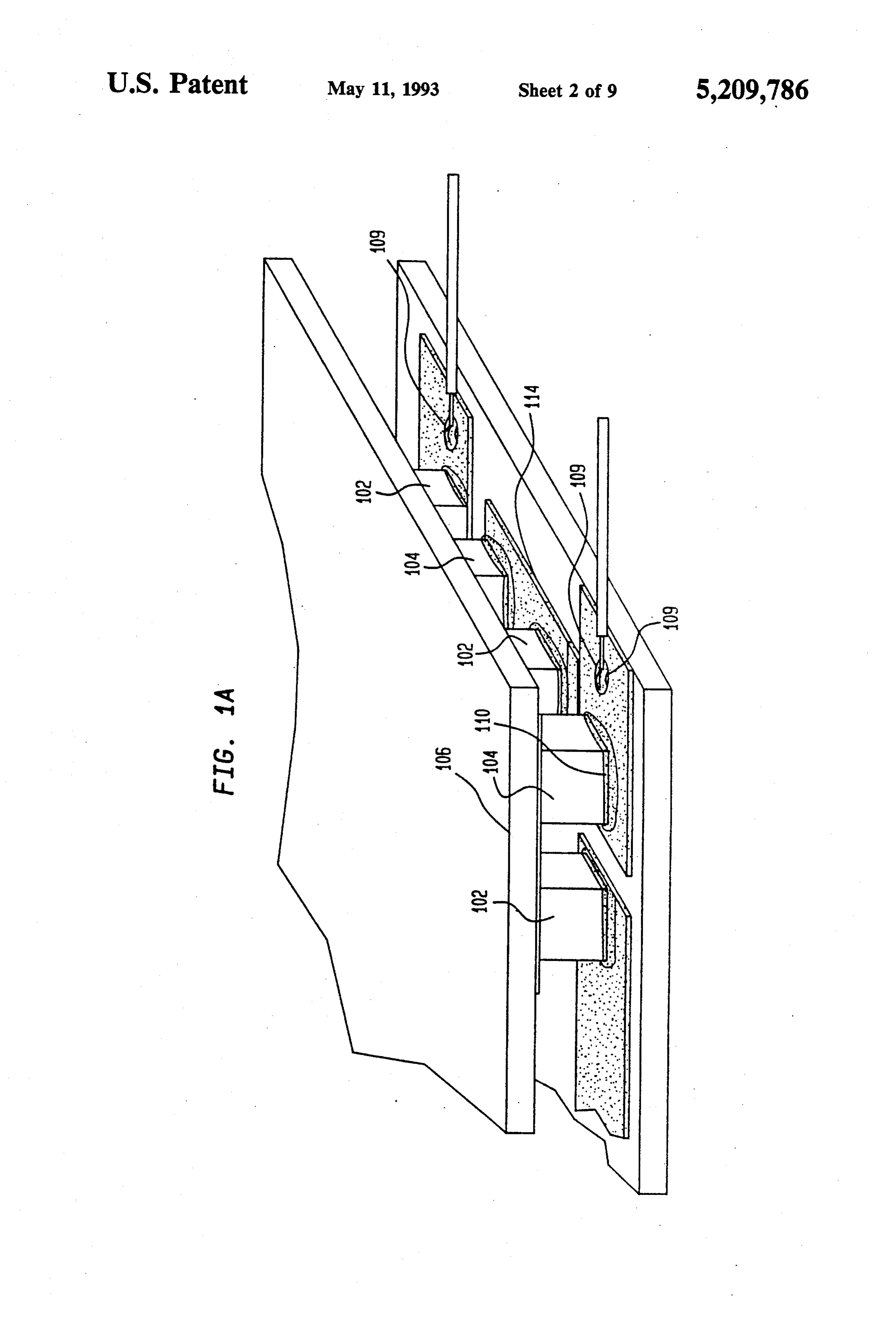
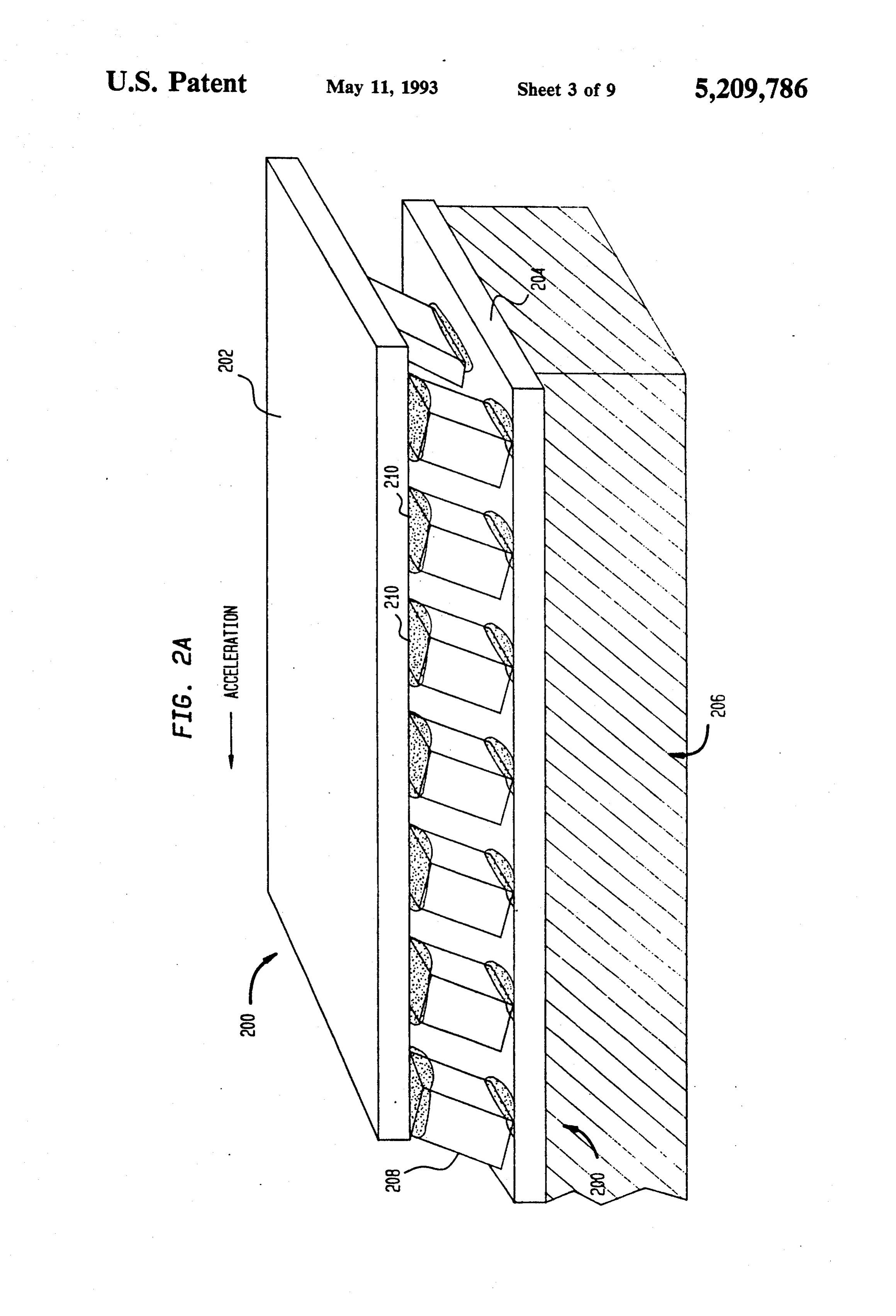
bonded to the surface of the plate defining the inter FIG. 1a is a view in perspective of a portion of a space and to the first end of said p-doped leg and the 65 thermoelectric device similar to that of of FIG. 1. first end of said n-doped leg. In this embodiment the FIG.2a is a view of a thermoelectric device similar to syntactic foam may comprise epoxy resin and also com that of FIG. 1 indicating likely shear failure/fracture prise hollow glass spheres. Preferably, the device fur points.
Page 13
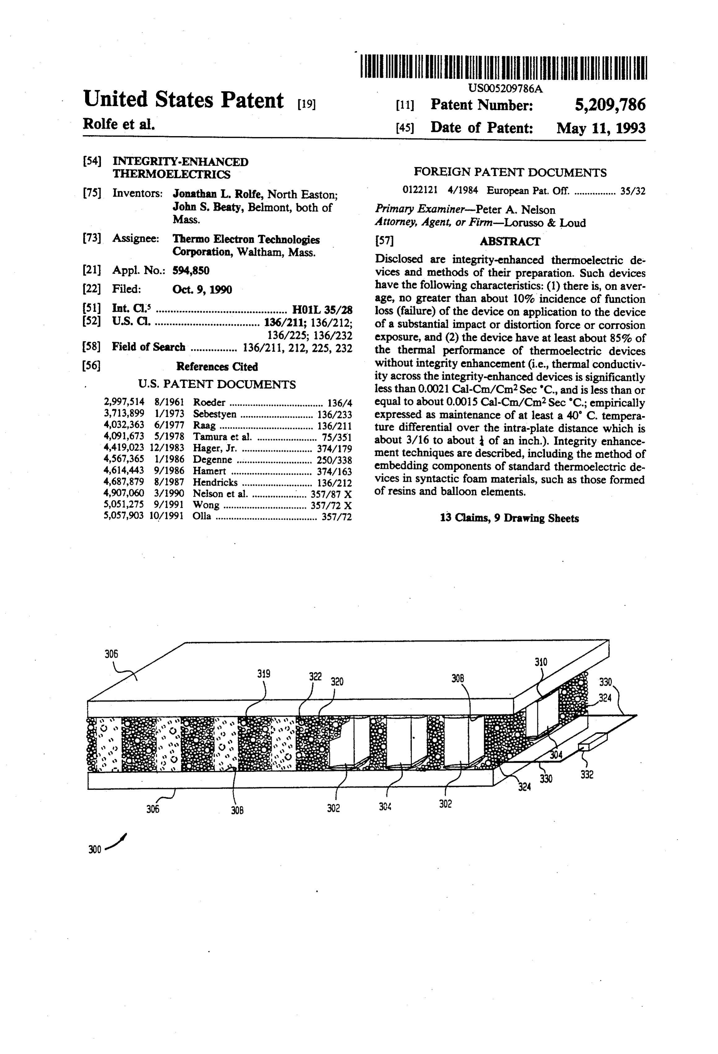
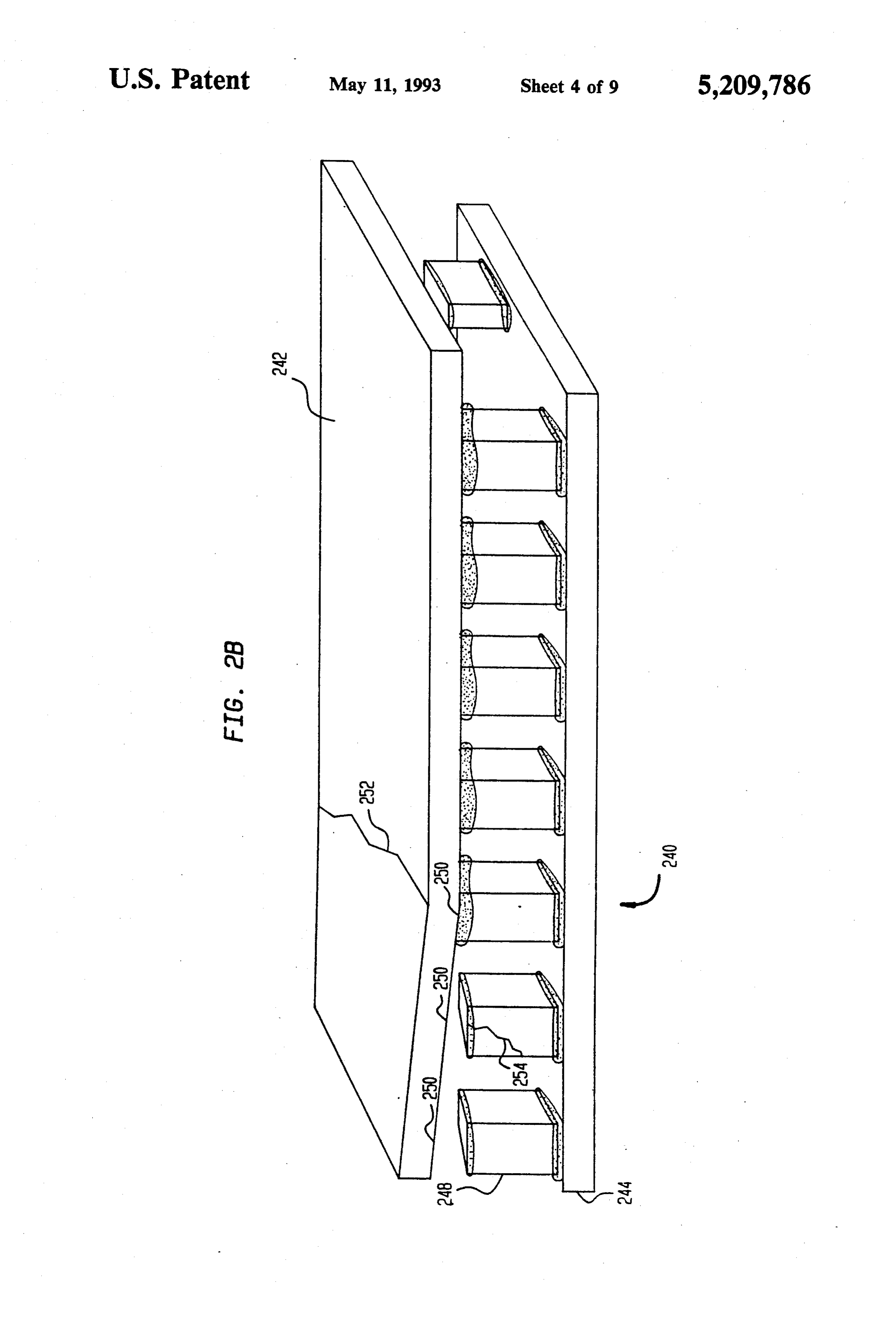
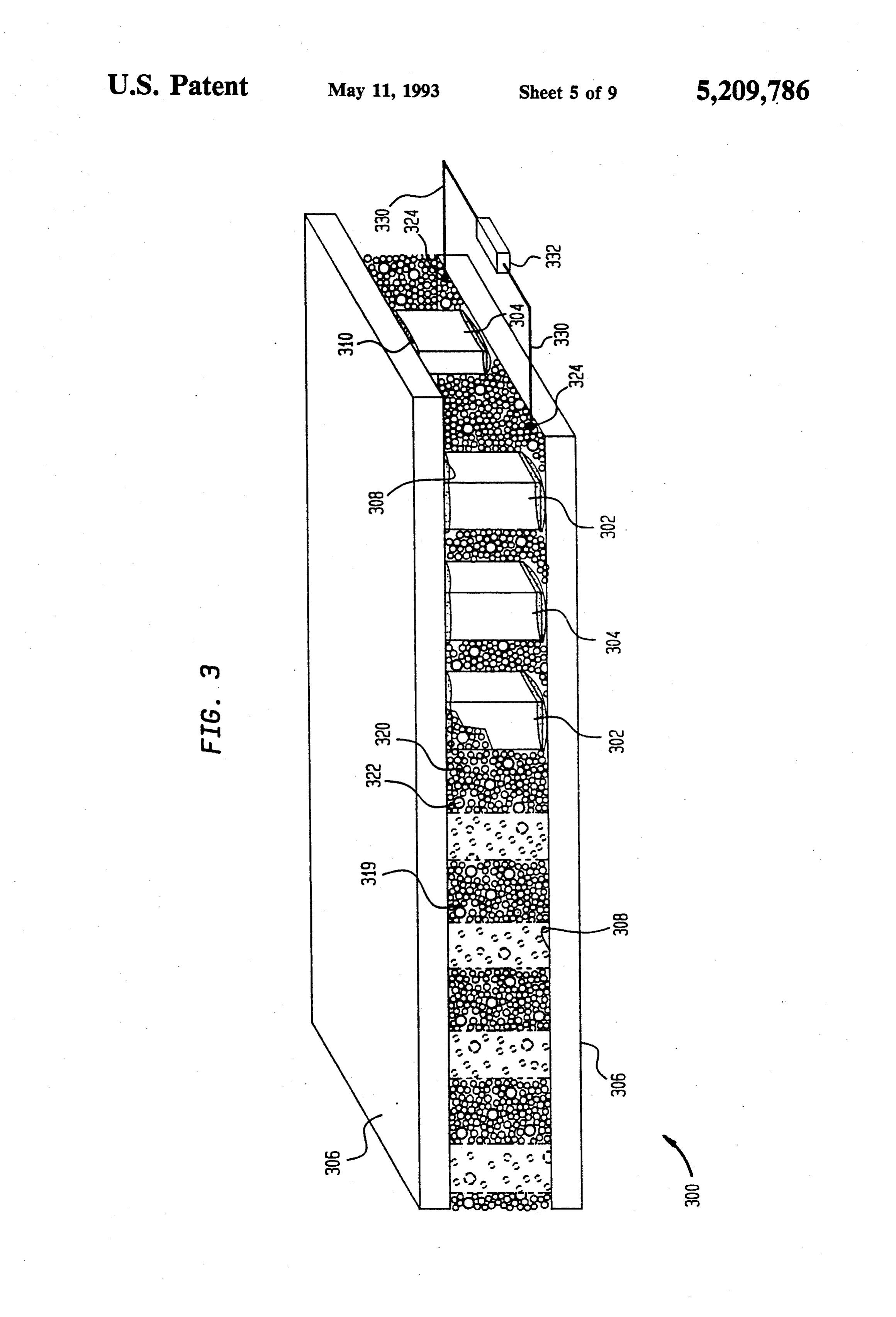
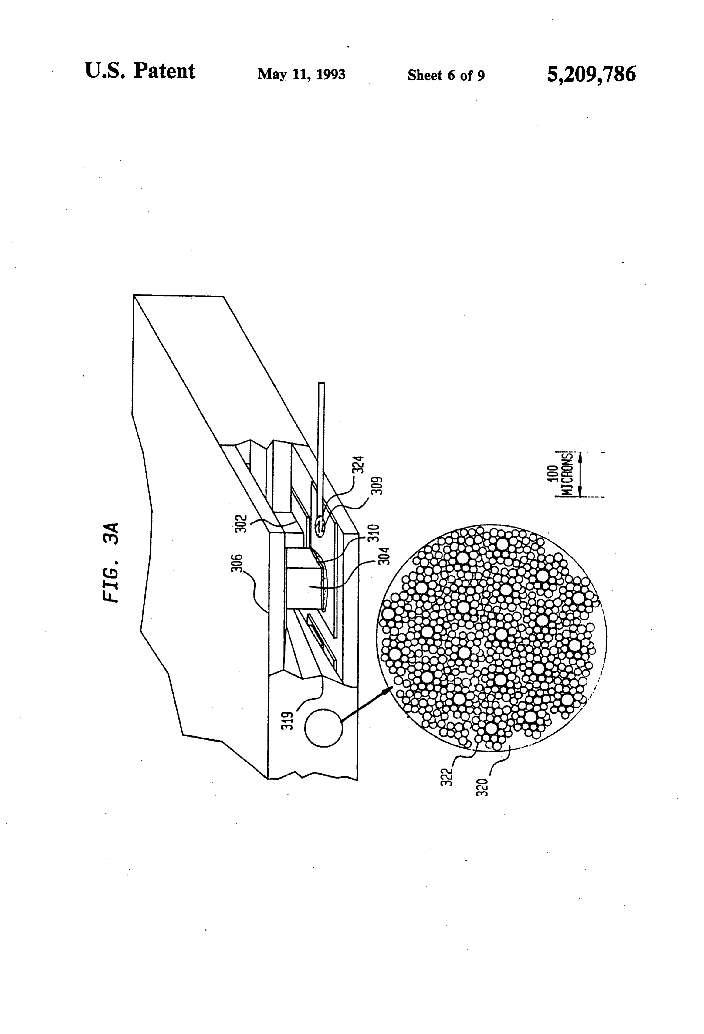
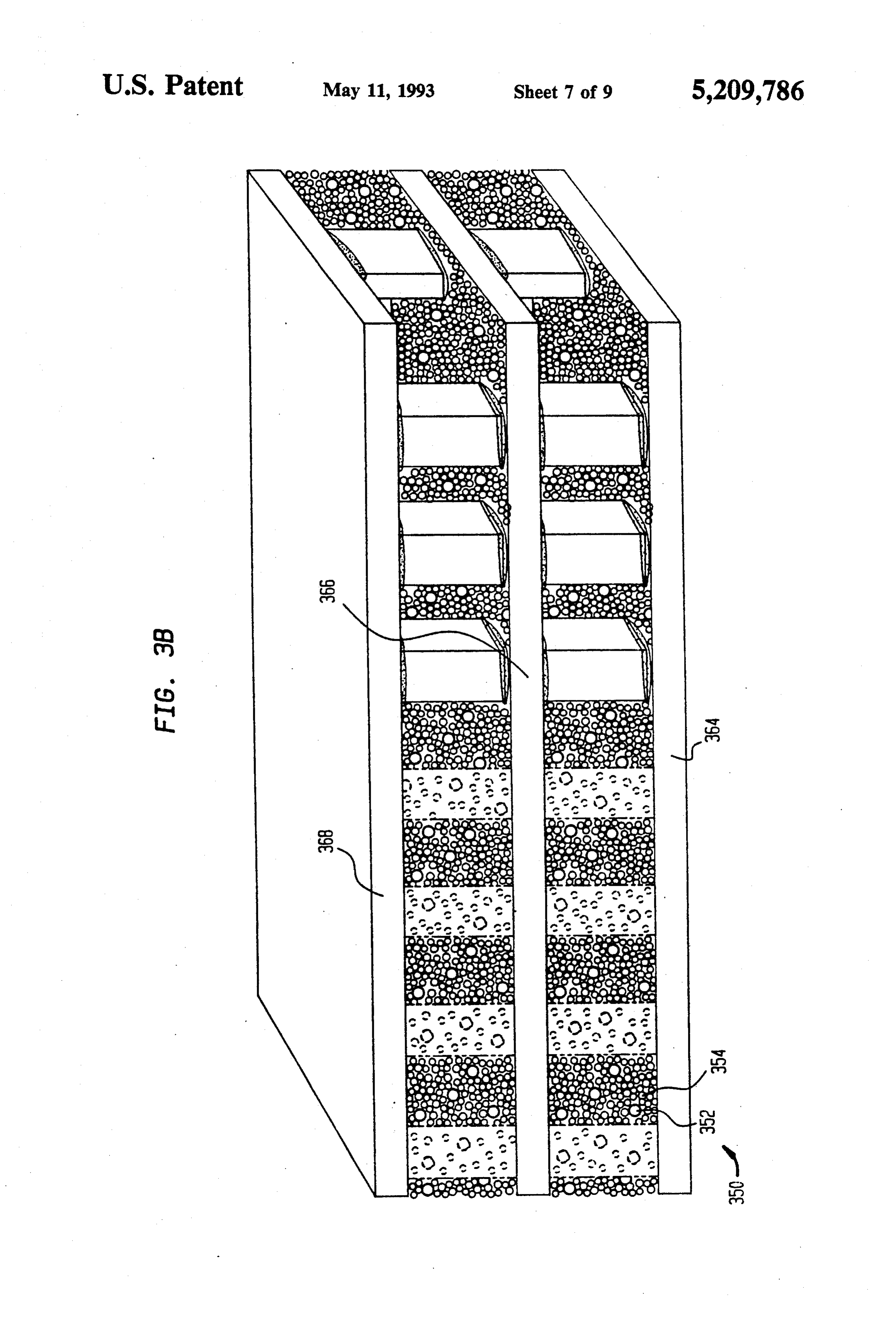
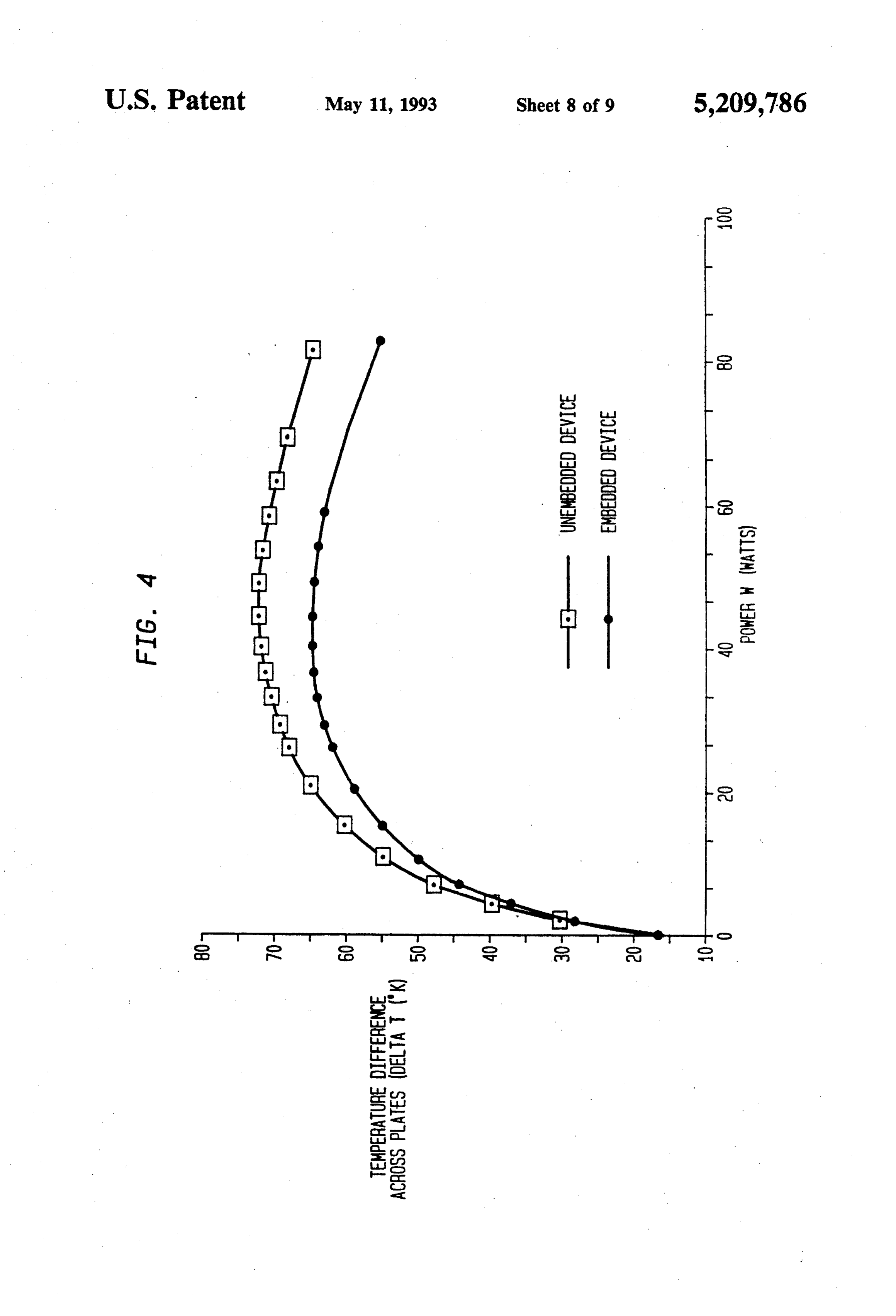
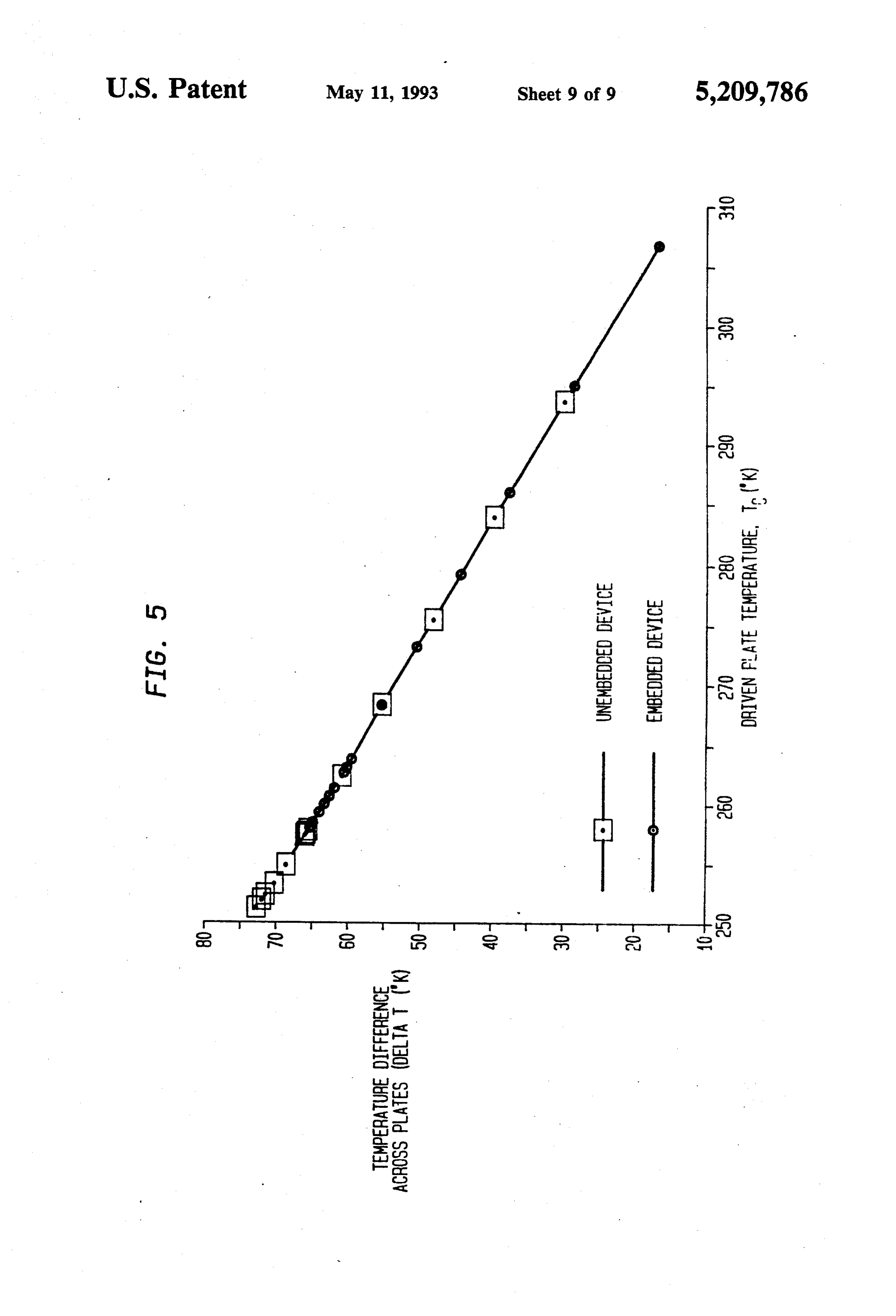
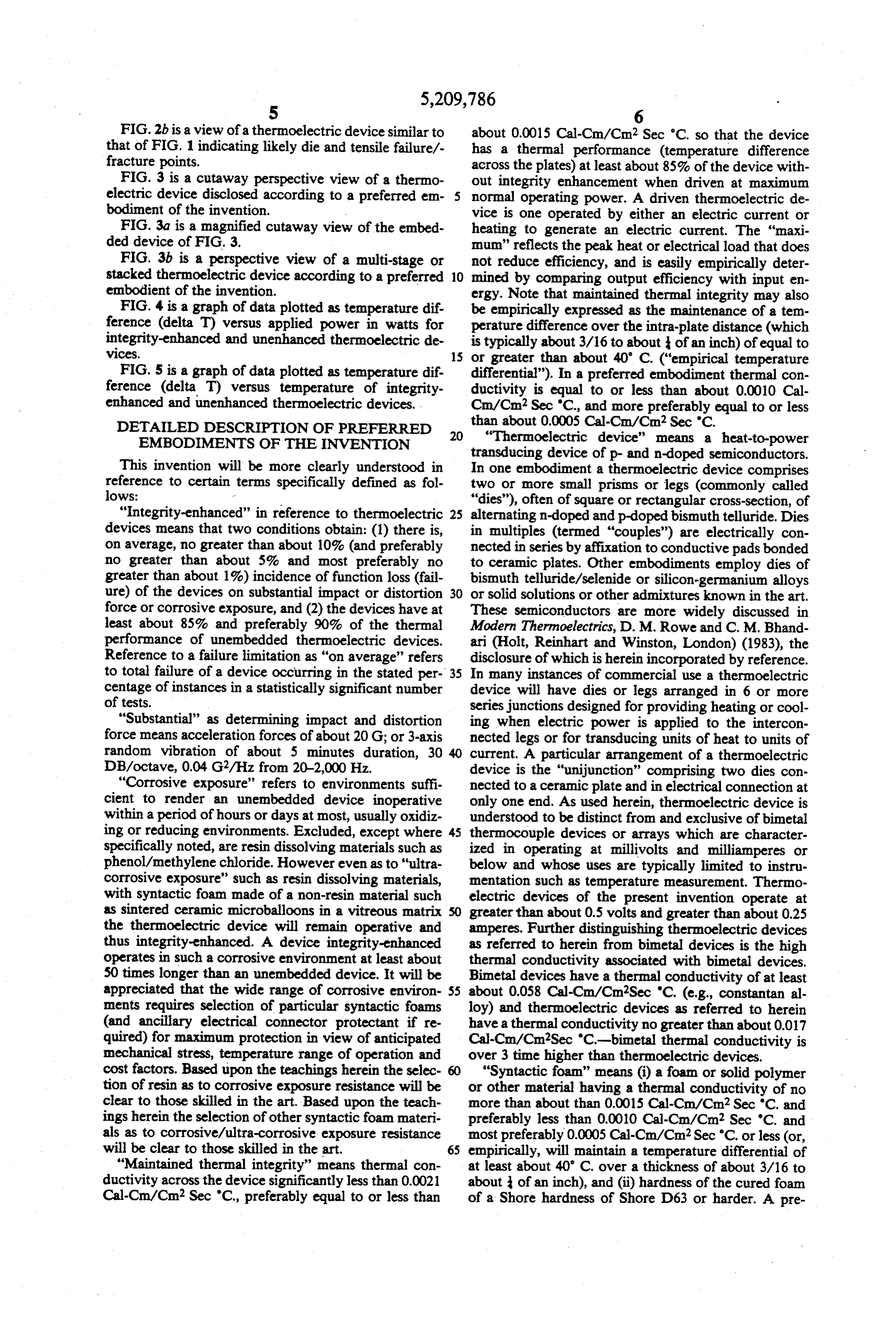
FIG.2b is a view of a thermoelectric device similar to about 0.0015 Cal-Cm/Cm2 Sec 'C. so that the device that of FIG. 1 indicating likely die and tensile failure/-has a thermal performance (temperature difference fracture points. across the plates) at least about 85% of the device with FIG. 3 is a cutaway perspective view of a thermo out integrity enhancement when driven at maximum electric device disclosed according to a preferred em normal operating power. A driven thermoelectric de bodiment of the invention. vice is one operated by either an electric current or FIG. 3a is a magnified cutaway view of the embed heating to generate an electric current. The "maxi ded device of FIG. 3. mum' reflects the peak heat or electrical load that does FIG. 3b is a perspective view of a multi-stage or not reduce efficiency, and is easily empirically deter stacked thermoelectric device according to a preferred 10 mined by comparing output efficiency with input en embodient of the invention. ergy. Note that maintained thermal integrity may also FIG. 4 is a graph of data plotted as temperature dif be empirically expressed as the maintenance of a tem ference (delta T) versus applied power in watts for perature difference over the intra-plate distance (which integrity-enhanced and unenhanced thermoelectric de is typically about 3/16 to about of an inch) of equal to VCS. 15 or greater than about 40' C. ("empirical temperature FIG. 5 is a graph of data plotted as temperature dif differential"). In a preferred embodiment thermal con ference (delta T) versus temperature of integrity ductivity is equal to or less than about 0.0010 Cal enhanced and unenhanced thermoelectric devices. Cm/Cm? Sec 'C., and more preferably equal to or less DETAILED DESCRIPTION OF PREFERRED than about 0.0005 Cal-Cm/Cm2 Sec 'C. EMBODIMENTS OF THE INVENTION 20 "Thermoelectric device' means a heat-to-power transducing device of p- and n-doped semiconductors.
This invention will be more clearly understood in In one embodiment a thermoelectric device comprises reference to certain terms specifically defined as fol two or more small prisms or legs (commonly called lows: "dies'), often of square or rectangular cross-section, of "Integrity-enhanced' in reference to thermoelectric 25 alternating n-doped and p-doped bismuth telluride. Dies devices means that two conditions obtain: (1) there is, in multiples (termed "couples') are electrically con on average, no greater than about 10% (and preferably nected in series by affixation to conductive pads bonded no greater than about 5% and most preferably no to ceramic plates. Other embodiments employ dies of greater than about 1%) incidence of function loss (fail bismuth telluride/selenide or silicon-germanium alloys ure) of the devices on substantial impact or distortion 30 or solid solutions or other admixtures known in the art. force or corrosive exposure, and (2) the devices have at These semiconductors are more widely discussed in least about 85% and preferably 90% of the thermal Modern Thermoelectrics, D. M. Rowe and C. M. Bhand performance of unembedded thermoelectric devices. ari (Holt, Reinhart and Winston, London) (1983), the Reference to a failure limitation as "on average" refers disclosure of which is herein incorporated by reference. to total failure of a device occurring in the stated per 35 In many instances of commercial use a thermoelectric centage of instances in a statistically significant number device will have dies or legs arranged in 6 or more of tests. series junctions designed for providing heating or cool "Substantial' as determining impact and distortion ing when electric power is applied to the intercon force means acceleration forces of about 20 G; or 3-axis nected legs or for transducing units of heat to units of random vibration of about 5 minutes duration, 30 current. A particular arrangement of a thermoelectric DB/octave, 0.04 G2/Hz from 20-2,000 Hz. device is the "unijunction' comprising two dies con "Corrosive exposure' refers to environments suffi nected to a ceramic plate and in electrical connection at cient to render an unembedded device inoperative only one end. As used herein, thermoelectric device is within a period of hours or days at most, usually oxidiz understood to be distinct from and exclusive of bimetal ing or reducing environments. Excluded, except where 45 thermocouple devices or arrays which are character specifically noted, are resin dissolving materials such as ized in operating at millivolts and milliamperes or phenol/methylene chloride. However even as to "ultra below and whose uses are typically limited to instru corrosive exposure' such as resin dissolving materials, mentation such as temperature measurement. Thermo with syntactic foam made of a non-resin material such electric devices of the present invention operate at as sintered ceramic microballoons in a vitreous matrix greater than about 0.5 volts and greater than about 0.25 the thermoelectric device will remain operative and amperes. Further distinguishing thermoelectric devices thus integrity-enhanced. A device integrity-enhanced as referred to herein from bimetal devices is the high operates in such a corrosive environment at least about thermal conductivity associated with bimetal devices. 50 times longer than an unembedded device. It will be Bimetal devices have a thermal conductivity of at least appreciated that the wide range of corrosive environ 55 about 0.058 Cal-Cm/Cm?Sec 'C. (e.g., constantan al ments requires selection of particular syntactic foams loy) and thermoelectric devices as referred to herein (and ancillary electrical connector protectant if re have athermal conductivity no greater than about 0.017 quired) for maximum protection in view of anticipated Cal-Cm/Cm?Sec 'C.-bimetal thermal conductivity is mechanical stress, temperature range of operation and over 3 time higher than thermoelectric devices. cost factors. Based upon the teachings herein the selec "Syntactic foam' means (i) a foam or solid polymer tion of resin as to corrosive exposure resistance will be or other material having a thermal conductivity of no clear to those skilled in the art. Based upon the teach more than about than 0.0015 Cal-Cm/Cm? Sec 'C. and ings herein the selection of other syntactic foam materi preferably less than 0.0010 Cal-Cm/Cm? Sec 'C. and als as to corrosive/ultra-corrosive exposure resistance most preferably 0.0005 Cal-Cm/Cm?Sec "C. or less (or, will be clear to those skilled in the art. 65 empirically, will maintain a temperature differential of "Maintained thermal integrity” means thermal con at least about 40' C. over a thickness of about 3/16 to ductivity across the device significantly less than 0.0021 about of an inch), and (ii) hardness of the cured foam Cal-Cm/Cm? Sec 'C., preferably equal to or less than of a Shore hardness of Shore D63 or harder. A pre
Page 14
ferred quality of the syntactic foam employed in the stantially reduces its mass, permitting rapid temperature integrity-enhanced thermoelectric devices of the pres . adjustment of the driven plate. This permits adjustment ent invention is a dielectric strength of at least 600 or slew on the order of a 40' C. change in less than V/mil and preferably 1000 W/mil or greater. In one about 20 seconds, or more preferably, in less than about embodiment, the above mentioned parameters are 10 seconds. Solid resins could not approach such a rapid achieved by selection of ingredients employed in foam slew rate.
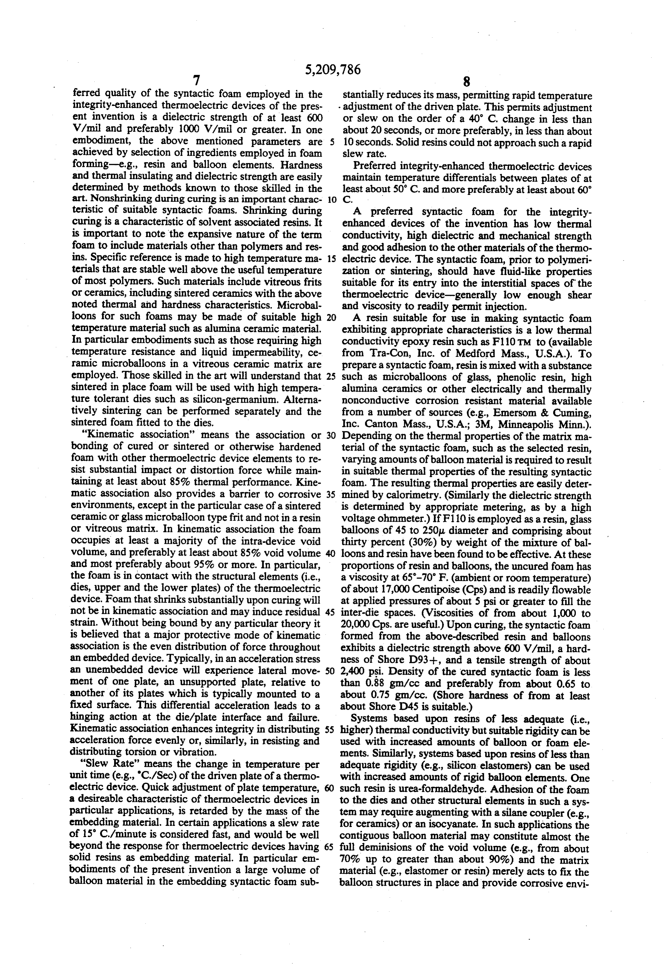
forming-e.g., resin and balloon elements. Hardness Preferred integrity-enhanced thermoelectric devices and thermal insulating and dielectric strength are easily maintain temperature differentials between plates of at determined by methods known to those skilled in the least about 50° C. and more preferably at least about 60' art. Nonshrinking during curing is an important charac O C teristic of suitable syntactic foams. Shrinking during A preferred syntactic foam for the integrity curing is a characteristic of solvent associated resins. It enhanced devices of the invention has low thermal is important to note the expansive nature of the term conductivity, high dielectric and mechanical strength foam to include materials other than polymers and res and good adhesion to the other materials of the thermo ins. Specific reference is made to high temperature ma 15 electric device. The syntactic foam, prior to polymeri terials that are stable well above the useful temperature zation or sintering, should have fluid-like properties of most polymers. Such materials include vitreous frits suitable for its entry into the interstitial spaces of the or ceramics, including sintered ceramics with the above thermoelectric device-generally low enough shear noted thermal and hardness characteristics. Microbal and viscosity to readily permit injection. loons for such foams may be made of suitable high 20 A resin suitable for use in making syntactic foam temperature material such as alumina ceramic material. exhibiting appropriate characteristics is a low thermal In particular embodiments such as those requiring high conductivity epoxy resin such as F110 TM to (available temperature resistance and liquid impermeability, ce from Tra-Con, Inc. of Medford Mass., U.S.A.). To ramic microballoons in a vitreous ceramic matrix are prepare a syntactic foam, resin is mixed with a substance employed. Those skilled in the art will understand that 25 such as microballoons of glass, phenolic resin, high sintered in place foam will be used with high tempera alumina ceramics or other electrically and thermally ture tolerant dies such as silicon-germanium. Alterna nonconductive corrosion resistant material available tively sintering can be performed separately and the from a number of sources (e.g., Emerson & Cuming, sintered foam fitted to the dies. Inc. Canton Mass., U.S.A.; 3M, Minneapolis Minn.). "Kinematic association' means the association or 30 Depending on the thermal properties of the matrix ma bonding of cured or sintered or otherwise hardened terial of the syntactic foam, such as the selected resin, foam with other thermoelectric device elements to re varying amounts of balloon material is required to result sist substantial impact or distortion force while main in suitable thermal properties of the resulting syntactic taining at least about 85% thermal performance. Kine foam. The resulting thermal properties are easily deter matic association also provides a barrier to corrosive 35 mined by calorimetry. (Similarly the dielectric strength environments, except in the particular case of a sintered is determined by appropriate metering, as by a high ceramic or glass microballoon type frit and not in a resin voltage ohmmeter.) If F110 is employed as a resin, glass or vitreous matrix. In kinematic association the foam balloons of 45 to 250 diameter and comprising about occupies at least a majority of the intra-device void thirty percent (30%) by weight of the mixture of bal volume, and preferably at least about 85% void volume loons and resin have been found to be effective. At these and most preferably about 95% or more. In particular, proportions of resin and balloons, the uncured foam has the foam is in contact with the structural elements (i.e., a viscosity at 65-70 F. (ambient or room temperature) dies, upper and the lower plates) of the thermoelectric of about 17,000 Centipoise (Cps) and is readily flowable device. Foam that shrinks substantially upon curing will at applied pressures of about 5 psi or greater to fill the not be in kinematic association and may induce residual 45 inter-die spaces. (Viscosities of from about 1,000 to strain. Without being bound by any particular theory it 20,000 Cps. are useful.) Upon curing, the syntactic foam is believed that a major protective mode of kinematic formed from the above-described resin and balloons association is the even distribution of force throughout exhibits a dielectric strength above 600 W/mil, a hard an embedded device. Typically, in an acceleration stress ness of Shore D93+, and a tensile strength of about an unembedded device will experience lateral move SO 2,400 psi. Density of the cured syntactic foam is less ment of one plate, an unsupported plate, relative to than 0.88 gm/cc and preferably from about 0.65 to another of its plates which is typically mounted to a about 0.75 gm/cc. (Shore hardness of from at least fixed surface. This differential acceleration leads to a about Shore D45 is suitable.) hinging action at the die/plate interface and failure. Systems based upon resins of less adequate (i.e., Kinematic association enhances integrity in distributing 55 higher) thermal conductivity but suitable rigidity can be acceleration force evenly or, similarly, in resisting and used with increased amounts of balloon or foam ele distributing torsion or vibration. ments. Similarly, systems based upon resins of less than "Slew Rate' means the change in temperature per adequate rigidity (e.g., silicon elastomers) can be used unit time (e.g., "C/Sec) of the driven plate of a thermo with increased amounts of rigid balloon elements. One electric device. Quick adjustment of plate temperature, such resin is urea-formaldehyde. Adhesion of the foam a desireable characteristic of thermoelectric devices in to the dies and other structural elements in such a sys particular applications, is retarded by the mass of the ten may require augmenting with a silane coupler (e.g., embedding material. In certain applications a slew rate for ceramics) or an isocyanate. In such applications the of 15 C/minute is considered fast, and would be well contiguous balloon material may constitute almost the beyond the response for thermoelectric devices having 65 full deminisions of the void volume (e.g., from about solid resins as embedding material. In particular en 70% up to greater than about 90%) and the matrix bodiments of the present invention a large volume of material (e.g., elastomer or resin) merely acts to fix the balloon material in the embedding syntactic foam sub balloon structures in place and provide corrosive envi
Page 15
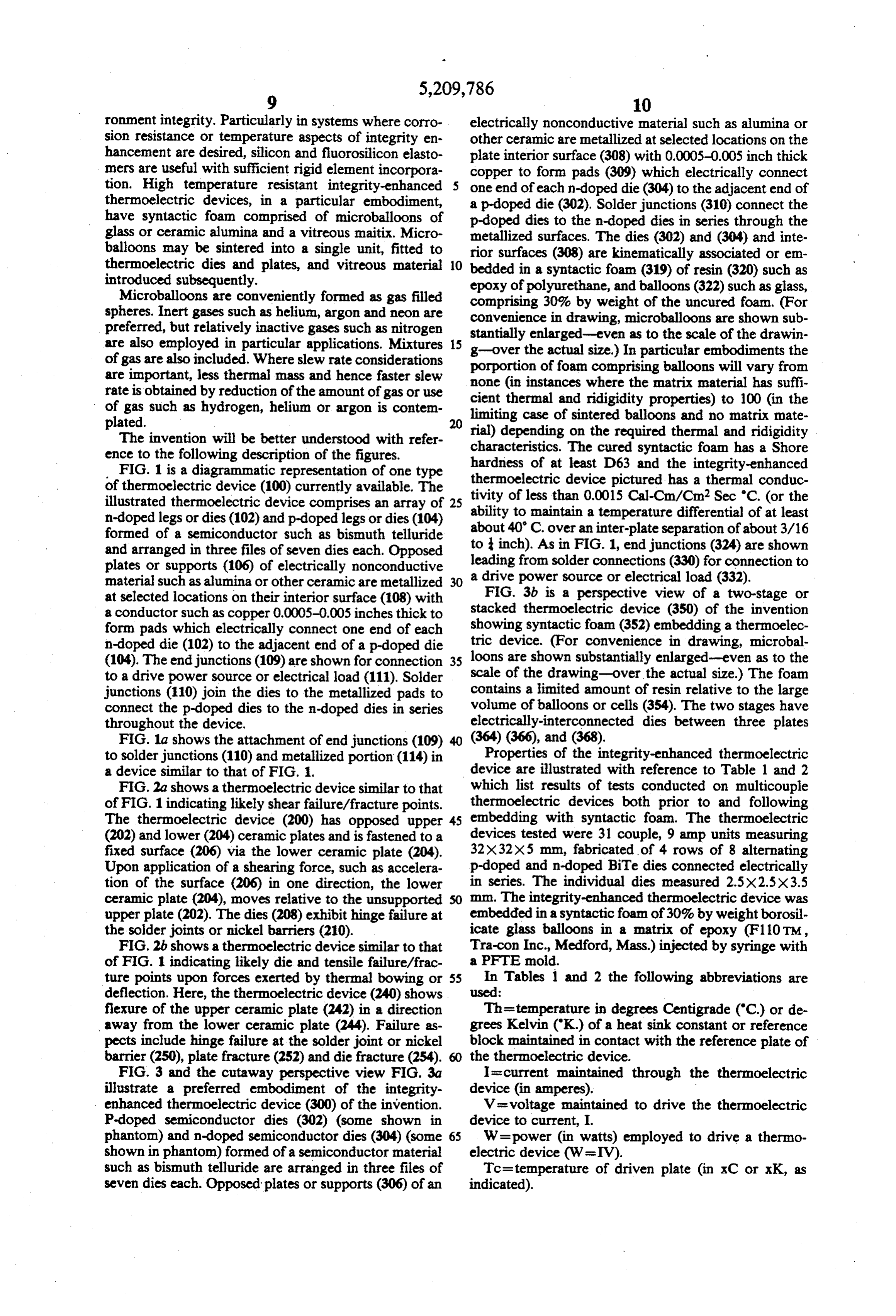
ronment integrity. Particularly in systems where corro electrically nonconductive material such as alumina or sion resistance or temperature aspects of integrity en other ceramic are metallized at selected locations on the hancement are desired, silicon and fluorosilicon elasto plate interior surface (308) with 0.0005–0.005 inch thick mers are useful with sufficient rigid element incorpora copper to form pads (309) which electrically connect tion. High temperature resistant integrity-enhanced one end of each n-doped die (304) to the adjacent end of thermoelectric devices, in a particular embodiment, a p-doped die (302). Solder junctions (310) connect the have syntactic foam comprised of microballoons of p-doped dies to the n-doped dies in series through the glass or ceramic alumina and a vitreous maitix. Micro metallized surfaces. The dies (302) and (304) and inte balloons may be sintered into a single unit, fitted to rior surfaces (308) are kinematically associated or em thermoelectric dies and plates, and vitreous material 10 bedded in a syntactic foam (319) of resin (320) such as introduced subsequently. epoxy of polyurethane, and balloons (322) such as glass, Microballoons are conveniently formed as gas filled comprising 30% by weight of the uncured foam. (For spheres. Inert gases such as helium, argon and neon are convenience in drawing, microballoons are shown sub preferred, but relatively inactive gases such as nitrogen are also employed in particular applications. Mixtures 15 stantially enlarged-even as to the scale of the drawin of gas are also included. Where slew rate considerations porportion ofactual g-over the foam size.) In particular embodiments the comprising balloons will vary from are important, less thermal mass and hence faster slew none (in instances where the matrix material has suffi rate is obtained by reduction of the amount of gas or use cient thermal and ridigidity properties) to 100 (in the of gas such as hydrogen, helium or argon is contem limiting case of sintered balloons and no matrix mate
rial) depending on the required thermal and ridigidity
The invention will be better understood with refer ence to the following description of the figures. characteristics. The cured syntactic foam has a Shore FIG. 1 is a diagrammatic representation of one type hardness of at device least D63 and the integrity-enhanced of thermoelectric device (100) currently available. The thermoelectric tivity of less than pictured has a thermal conduc
illustrated thermoelectric device comprises an array of ability to maintain a temperature
differential of at least n-doped legs or dies (102) and p-doped legs or dies (104) formed of a semiconductor such as bismuth telluride about 40 C. over an inter-plate separation of about 3/16 and arranged in three files of seven dies each. Opposed to inch). As in FIG. 1, end junctions (324) are shown plates or supports (106) of electrically nonconductive leading from solder connections (330) for connection to material such as alumina or other ceramic are metallized 30 a drive power source or electrical load (332). at selected locations on their interior surface (108) with FIG. 3b is a perspective view of a two-stage or a conductor such as copper 0.0005-0.005 inches thick to stacked thermoelectric device (350) of the invention form pads which electrically connect one end of each showing syntactic foam (352) embedding a thermoelec n-doped die (102) to the adjacent end of a p-doped die tric device. (For convenience in drawing, microbal (104). The end junctions (109) are shown for connection 35 loons are shown substantially enlarged-even as to the to a drive power source or electrical load (111). Solder scale of the drawing-over the actual size.) The foam junctions (110) join the dies to the metallized pads to contains a limited amount of resin relative to the large connect the p-doped dies to the n-doped dies in series volume of balloons or cells (354). The two stages have throughout the device. electrically-interconnected dies between three plates FIG. 1a shows the attachment of end junctions (109) (364) (366), and (368).
to solder junctions (110) and metallized portion (114) in Properties of the integrity-enhanced thermoelectric a device similar to that of FIG, . device are illustrated with reference to Table 1 and 2 FIG.2a shows a thermoelectric device similar to that which list results of tests conducted on multicouple of FIG. 1 indicating likely shear failure/fracture points. thermoelectric devices both prior to and following The thermoelectric device (200) has opposed upper 45 embedding with syntactic foam. The thermoelectric (202) and lower (204) ceramic plates and is fastened to a devices tested were 31 couple, 9 amp units measuring fixed surface (206) via the lower ceramic plate (204). 32X32X5 mm, fabricated of 4 rows of 8 alternating Upon application of a shearing force, such as accelera p-doped and n-doped BiTe dies connected electrically tion of the surface (206) in one direction, the lower in series. The individual dies measured 2.5X2.5X3.5 ceramic plate (204), moves relative to the unsupported mm. The integrity-enhanced thermoelectric device was upper plate (202). The dies (208) exhibithinge failure at embedded in a syntactic foam of 30% by weight borosil the solder joints or nickel barriers (210). icate glass balloons in a matrix of epoxy (F110 TM, FIG.2b shows a thermoelectric device similar to that Tra-con Inc., Medford, Mass.) injected by syringe with of FIG. 1 indicating likely die and tensile failure/frac a PFTE mold.
ture points upon forces exerted by thermal bowing or 55 In Tables 1 and 2 the following abbreviations are deflection. Here, the thermoelectric device (240) shows used:
flexure of the upper ceramic plate (242) in a direction Th=temperature in degrees Centigrade (C) or de away from the lower ceramic plate (244). Failure as grees Kelvin (K) of a heat sink constant or reference pects include hinge failure at the solder joint or nickel block maintained in contact with the reference plate of barrier (250), plate fracture (252) and die fracture (254). the thermoelectric device.
FIG. 3 and the cutaway perspective view FIG. 3a I=current maintained through the thermoelectric illustrate a preferred embodiment of the integrity device (in amperes).
enhanced thermoelectric device (300) of the invention. V=voltage maintained to drive the thermoelectric P-doped semiconductor dies (302) (some shown in device to current, I.
phantom) and n-doped semiconductor dies (304) (some W=power (in watts) employed to drive a thermo shown in phantom) formed of a semiconductor material electric device (W=IV).
such as bismuth telluride are arranged in three files of Tc=temperature of driven plate (in xC or xK, as seven dies each. Opposed plates or supports (306) of an indicated).
Page 16
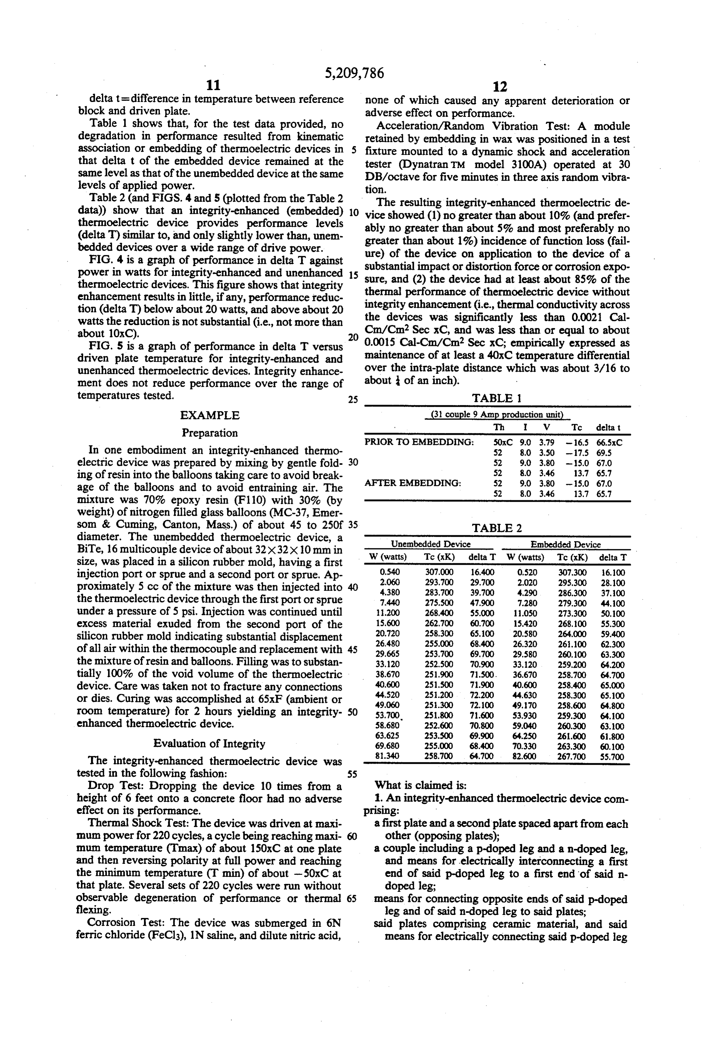
delta t = difference in temperature between reference none of which caused any apparent deterioration or block and driven plate. adverse effect on performance. Table 1 shows that, for the test data provided, no Acceleration/Random Vibration Test: A module degradation in performance resulted from kinematic retained by embedding in wax was positioned in a test association or embedding of thermoelectric devices in fixture mounted to a dynamic shock and acceleration that delta t of the embedded device remained at the tester (Dynatran TM model 3100A) operated at 30 same level as that of the unembedded device at the same DB/octave for five minutes in three axis random vibra levels of applied power. tion.
Table 2 (and FIGS. 4 and 5 (plotted from the Table 2 The resulting integrity-enhanced thermoelectric de data)) show that an integrity-enhanced (embedded) 10 vice thermoelectric device provides performance levels ably showed no (1) no greater than about 10% (and prefer greater than about 5% and most preferably no (delta T) similar to, and only slightly lower than, unem greater than about 1%) incidence of function loss (fail bedded devices over a wide range of drive power.
FIG. 4 is a graph of performance in delta T against substantial impact orondistortion ure) of the device application to the device of a force or corrosion expo power in watts for integrity-enhanced and unenhanced 15 sure, and (2) the device had at least about 85% of the thermoelectric devices. This figure shows that integrity enhancement results in little, if any, performance reduc thermal performance of thermoelectric device without tion (delta T) below about 20 watts, and above about 20 integrity enhancement (i.e., thermal conductivity across watts the reduction is not substantial (i.e., not more than the devices was significantly less than 0.0021 Cal about 10xC). 20 Cm/Cm2 Sec xC, and was less than or equal to about FIG. 5 is a graph of performance in delta T versus 0.0015 Cal-Cm/Cm2 Sec xC; empirically expressed as driven plate temperature for integrity-enhanced and maintenance of at least a 40xC temperature differential unenhanced thermoelectric devices. Integrity enhance over the intra-plate distance which was about 3/16 to ment does not reduce performance over the range of about of an inch).
temperatures tested. 25 TABLE 1 EXAMPLE 31 couple 9 Amp production unit
Preparation
In one embodiment an integrity-enhanced thermo 52 8.0 3.50 - 17.5 69.5 electric device was prepared by mixing by gentle fold 30 52 9.0 3.80 - 15.0 67.0 ing of resin into the balloons taking care to avoid break AFTER EMBEDDING: S2 8.0 3.46 13.7 65.7
age of the balloons and to avoid entraining air. The 52 8.0 3.46 13.7 65.7 mixture was 70% epoxy resin (F110) with 30% (by weight) of nitrogen filled glass balloons (MC-37, Emer som & Cuming, Canton, Mass.) of about 45 to 250f 35 TABLE 2 diameter. The unembedded thermoelectric device, a Unenbedded Device Embedded Device BiTe, 16 multicouple device of about 32X32x10 mm in W (watts) Tc (xK) delta T W (watts) Tc (xK) delta T size, was placed in a silicon rubber mold, having a first injection port or sprue and a second port or sprue. Ap 0,540 3.07.000 16.400 0.520 307.300 6..100 proximately 5 cc of the mixture was then injected into 40 2.060
the thermoelectric device through the first port or sprue 7.440 275,500 47.900 7.280 279.300 44,100 under a pressure of 5 psi. Injection was continued until 1.200 268,400 SS.000 11.050 273.300 50.00 excess material exuded from the second port of the 1S,600
silicon rubber mold indicating substantial displacement 26.480 255.000 68,400 26.320 26.100 62.300 of all air within the thermocouple and replacement with 45 29,665 253.700 69,700 29,580 260.100 63.300 the mixture of resin and balloons. Filling was to substan 33.20 252.500 70,900 33.120 259,200 64.200 tially 100% of the void volume of the thermoelectric 38.670 251.900 71.500. 36,670 258.700 64.700 device. Care was taken not to fracture any connections 40,600 251.500 71.900 40.600 258.400 6S,000 or dies. Curing was accomplished at 65xF (ambient or 44.520 251.200 72.200 44.630 258.300 65.00
room temperature) for 2 hours yielding an integrity 50 53.700. 251.800 71.600. 53.930 259,300 64.00 enhanced thermoelectric device. 58,680 252.600 70,800 59.040 260.300 63.00
Evaluation of Integrity 69.680 255.000 68.400 70.330 263.300 60.100
The integrity-enhanced thermoelectric device was tested in the following fashion: 55
Drop Test: Dropping the device 10 times from a What is claimed is:
height of 6 feet onto a concrete floor had no adverse 1. An integrity-enhanced thermoelectric device com effect on its performance. prising:
Thermal Shock Test: The device was driven at maxi a first plate and a second plate spaced apart from each mum power for 220 cycles, a cycle being reaching maxi 60 other (opposing plates); mum temperature (Tmax) of about 150xC at one plate a couple including a p-doped leg and a n-doped leg, and then reversing polarity at full power and reaching and means for electrically interconnecting a first the minimum temperature (T min) of about -50xC at end of said p-doped leg to a first end of said n that plate. Several sets of 220 cycles were run without doped leg;
observable degeneration of performance or thermal 65 means for connecting opposite ends of said p-doped flexing. leg and of said n-doped leg to said plates; Corrosion Test: The device was submerged in 6N said plates comprising ceramic material, and said ferric chloride (FeCl3), 1N saline, and dilute nitric acid, means for electrically connecting said p-doped leg
Page 17
to said n-doped leg, comprising a metal pad bonded end of said p-doped leg to a first end of said n to the surface of the plate defining the interspace, doped leg;
and in electrical connection with a first end of said means for connecting opposite ends of said p-doped p-doped leg and a first end of said n-doped leg; leg and of said n-doped leg to said plates; at least two of said couples electrically connected in at least two of said couples electrically connected in series and having opposed ends connected to the series and having opposed ends connected to said opposing plate; plates;
said plates and said legs defining an interspace be said plates and said legs defining an interspace be tween said plates; tween said plates;
syntactic foam occupying said interspace and in kine 10 syntactic foam occupying said interspace and in kine matic association with said legs and plates to form matic association with said legs and plates to foam an embedded thermoelectric device; and an embedded thermoelectric device; and said syntactic foam comprising resin and hollow glass said syntactic foam comprising resin and hollow sin balloons which have about 180 to about 250p diam tered ceramic microballoons and comprising at eter and comprising at least about 30% by weight 15 least about 30% by weight of the mixture of bal of the mixture of balloons and resin, said hollow glass balloons being filled with one of inactive loons and resin, said hollow sintered ceramic mi gases or mixtures thereof. croballoons being filled with one of inactive gases 2. The device of claim 1 wherein said inactive gases or mixtures thereof.
comprise nitrogen. 20 8. The device of claim 7 wherein said inactive gases 3. The device of claim 1 wherein said inactive gases comprise nitrogen.
comprise inert gases. 9. The device of claim 7 wherein said inactive gases 4. The device of claim 3 wherein said inert gases comprise inert gases.
comprise helium, argon or neon. 10. The device of claim 9 wherein said inert gases 5. The device of claim 1 wherein said resin comprises 25 comprise helium, argon and neon. urea-formaldehyde. 11. The device of claim 7 wherein said resin com 6. The device of claim 1 wherein said resin comprises prises urea-formaldehyde.
epoxy resin. 12. The device of claim 7 wherein said resin con 7. An integrity-enhanced thermoelectric device com prises epoxy resin.
prising: a first plate and a second plate spaced apart 30 13. The device of claim 7 wherein said sintered ce from each other (opposing plates); ramic microballoons comprise high alumina ceramic a couple including a p-doped leg and a n-doped leg, microballoons.
and means for electrically interconnecting a first k is
Provenance
- Collection
- Cited prior art
- Original PDF
- patentimages.storage.googleapis.com →
- Filed
- 1990-10-09
- Pages
- 17
- Method
- pdftotext (the PDF's own text layer) + pdftoppm 300dpi page scans
- Source
- Google Patents bibliographic record
- Granted
- 1993-05-11
- Inventors
- Jonathan L. Rolfe; John S. Beaty; Thermo Electron Technologies Corp
- Transcribed from
- patentimages.storage.googleapis.com →