patent · US4157290
Coating arrangement
5 June 1979
Page 1 — bibliographic record
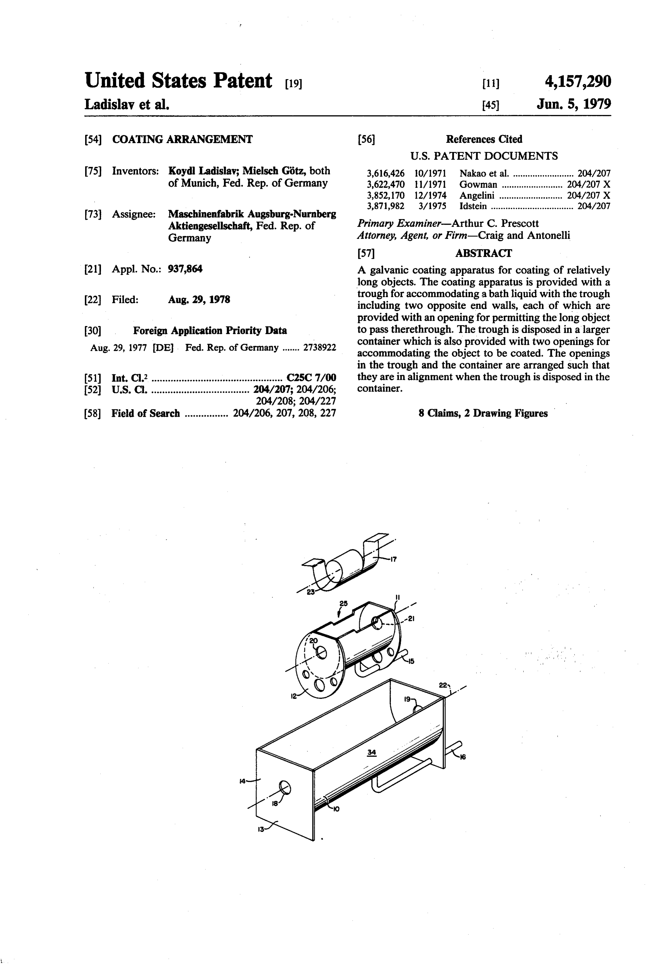
United States Patent 19 11) 4,157,290 Ladislav et al. 45) Jun. 5, 1979 (54) COATING ARRANGEMENT (56) References Cited
75 Inventors: Koyd Ladislav; Mielsch Götz, both 3,616,426 10/1971 Nakao et al. ......................... 204/2O7 of Munich, Fed. Rep. of Germany 3,622,470 1/1971 Gowman ...... ... 204/207 X 3,852,170 12/1974 Angelini ... ... 204/207 X 3,871,982 3/1975 Idstein .................................. 204/207 73 Assignee: Maschinenfabrik Augsburg-Nurnberg
Aktiengesellschaft, Fed. Rep. of Primary Examiner-Arthur C. Prescott
Germany Attorney, Agent, or Firm-Craig and Antonelli
(21) Appl. No.: 937,864 A galvanic coating apparatus for coating of relatively long objects. The coating apparatus is provided with a 22 Filed: Aug. 29, 1978 trough for accommodating a bath liquid with the trough including two opposite end walls, each of which are provided with an opening for permitting the long object 30 Foreign Application Priority Data to pass therethrough. The trough is disposed in a larger Aug. 29, 1977 DE, Fed. Rep. of Germany ....... 2738922 container which is also provided with two openings for accommodating the object to be coated. The openings in the trough and the container are arranged such that 51) Int. Cl’................................................ C25C 7/OO they are in alignment when the trough is disposed in the 52 U.S. C. .................................... 204/207; 204/206; container.
58 Field of Search ................ 204/206, 207,208, 227 8 Claims, 2 Drawing Figures
Page 2
Drawing sheet — no readable text.
Page 3
In situations wherein a particular coating is brittle or
COATING ARRANGEMENT wherein a coated surface must not be damaged, in order to avoid transporting such coated objects, according to
The present invention relates to a coating arrange yet another feature of the present invention, a series of ment and, more particularly, to a galvanic coating ar 5 the electrolytic cells may be divided into small-sized rangement for coating relatively long objects, which cells and combined with necessary assemblies so as to arrangement includes a trough or container for accom form a portable unit. By virtue of such an arrangement, modating a bath fluid. the coating process could be performed at any given To effect glavanic coating, it has been proposed to location. This is particularly advantageous and favor provide a container or, with relatively larger objects, a O able when installing "parabolic' solar collector arrays, so-called trough, filled with an electrolyte. The object for such arrays utilize long chrome-plated absorber to be coated is submerged in the electrolyte and con tubes which could then be chrome-plated directly on nected to an electrical circuit as a cathode. A disadvan the location where the solar array is to be erected, tage of this proposed coating construction resides in the thereby eliminating the need for careful packing of the fact that the container or trough must at least have the 15 absorber tubes to protect the relatively brittle chro dimensions of the object to be coated. mium coating during shipment.
The aim underlying the present invention essentially Advantageously, according to the present invention, resides in providing a coating apparatus for coating rinsing cells as well as de-greasing cells, pickling cells objects having a length which is larger than the cross and other cells may be interposed between the dual sectional dimensions of the object, with the length of 20 troughed electrolytic cells or the divided electrolytic the container or trough being independent of the length cells so that the total process, including the pre-treat of the object to be coated. 3. ment and intermediate treatment required for galvanic According to advantageous features of the present process, as well as for single and multiple coating, re invention, a container or trough is provided which duces the cost of the process to a significant degree by includes openings provided flush in two opposite walls 25 comparison with previous methods of processing. with the openings accommodating the object to be Moreover, with a coating apparatus constructed in coated. The trough or container is disposed in a larger accordance with the present invention, the heretofore trough or container which is also provided with two necessary devices for gripping the object and submerg openings in opposite end walls thereof, which two ing the same into a bath, subsequently lifting the object openings align with the openings in the first trough 30 out of the bath, transporting the object to adjacent cells, when the first trough is arranged in the second trough and subsequently dipping the transported object in the or container. adjacent cells, are eliminated. By virtue of the construction of a coating apparatus Accordingly, it is an object of the present invention in accordance with the features of the present invention, to provide a coating apparatus which avoids, by simple it is possible to, for example, process pipes in a relatively 35 means, drawbacks and disadvantages encountered in small container regardless of the length of such pipes, the prior art.
thereby resulting in a considerable savings with respect Another object of the present invention resides in to dimensions of the trough or container since such providing a coating apparatus wherein the dimensions dimensions are no longer dependent upon the length of of the trough or container are not dependent upon the the object to be coated. Moreover, by processing the 40 lengths of the objects to be coated. relatively long objects in relatively small containers or A further object of the present invention resides in troughs, a considerable reduction of the required bath providing a coating apparatus wherein a multiple coat volume is also realized. ing of an object is greatly facilitated. In accordance with the present invention, an object Yet another object of the present invention resides in passes through the aligned openings in the two troughs 45 providing a coating apparatus which significantly re or containers and is pulled through the electrolyte. Any duces the overall costs of a coating process. electrolyte which escapes through slot openings in the Still a further object of the present invention resides first trough or container drips into the second trough or in providing a coating apparatus which is simple in container and may be simultaneously and continuously construction and, therefore, inexpensive to manufac recycled to the top trough by an appropriate feed. By 50 tre.
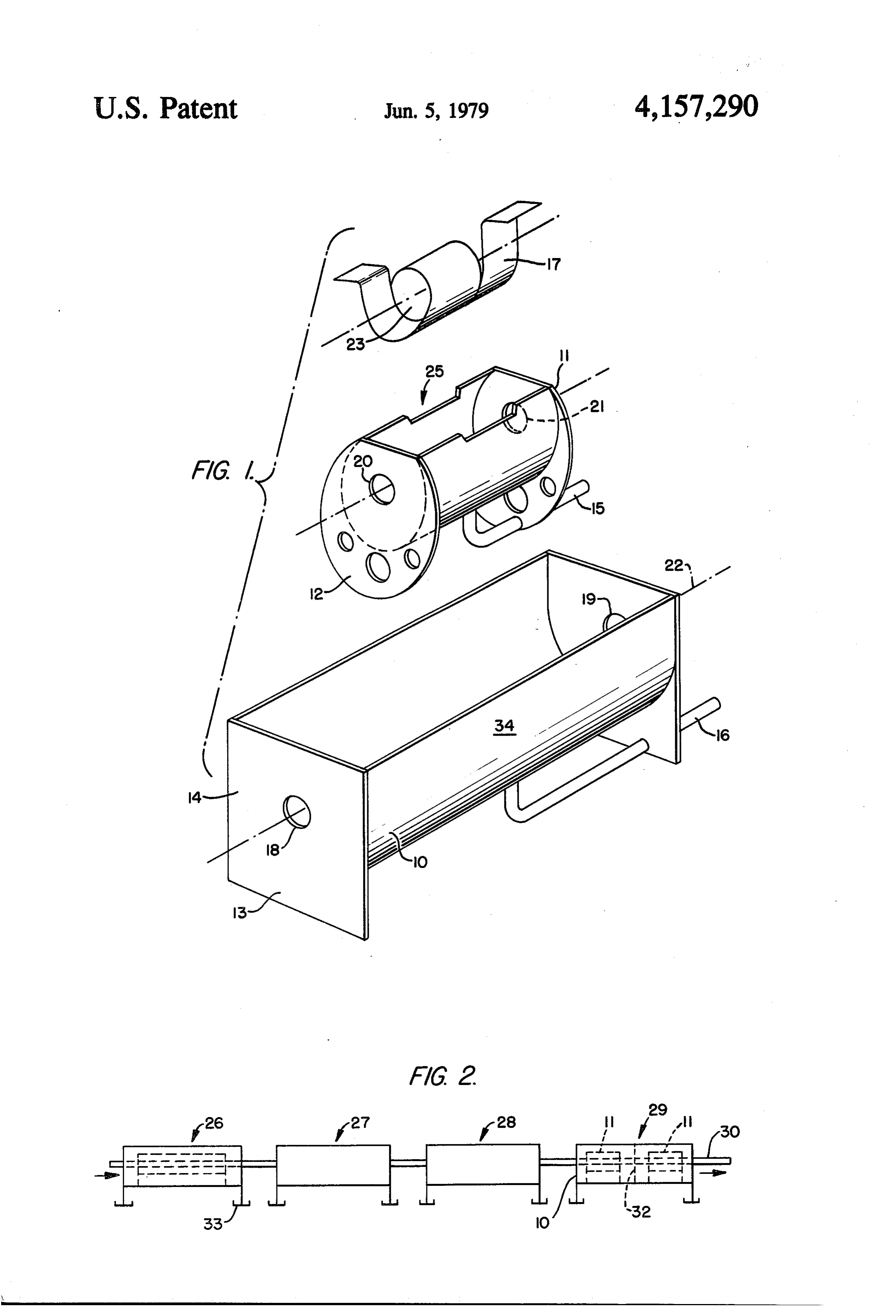
such an arrangement, a careful sealing of the first An additional object of the present invention resides trough or container is unnecessary, thereby simplifying in providing a coating apparatus which functions reli the manufacturing of the trough so as to provide addi ably under all operating conditions. tional cost reductions. These and other objects, features and advantages of According to the present invention, the second 55 the present invention will become more apparent from trough, may advantageously function as a supply tank the following description when taken in connection for the electrolytic solution with the electrolytic solu with the accompanying drawings which show, for the tion being recycled back into the bath formed in the first purpose of illustration only, one embodiment in accor trough in dependence upon the leak rate. dance with the present invention, and wherein: In situations wherein multiple coating is required as, FIG. 1 is an exploded perspective view of a coating for example, in black chrome plating of absorber tubes apparatus in accordance with the present invention; and for solar collectors wherein the absorber tubes are inti FIG. 2 is a schematic representation of a series con tially nickel-plated to make them accept a radiation nection of a plurality of coating apparatus such as illus absorbent chromium layer, according to a further fea trated in FIG. 1.
ture of the present invention, a plurality of dual-trough 65 Referring now to the drawings wherein like refer electrolytic cells may be connected in series so that an ence numerals are used in both views to designate like object to be coated can be guided in one pass through a parts and, more particularly, to FIG. 1, a coating trough series of baths. or container 11 is adapted to be installed or mounted in
Page 4
a larger collecting trough or container 10 with the A simplification from the manufacturing standpoint trough 11 being provided with downwardly projecting can be achieved by disposing the respective plates 13 in end walls 12. The trough 10 is mounted on plates 13 pans 33 which, for example, may be constructed of a which simultaneously form the end walls of the trough plastic material with the pans serving to catch any leaks or container 10. Conduits or pipes 15, 16 are connected from glued or welded seams between end walls 14 and at the deepest point of the respective containers 11, 10. a housing 34 of the container or trough 10. By virtue of The conduits or pipes 15, 16 may be connected to a this arrangement, a great degree of care need not be suitable pump (not shown) and/or a fluid supply (not exercised in the manufacturing of the trough or con shown) so that the respective pipes serve to both fill and O tainer 10.
empty the troughs 10, 11. A cylindrical anode 17 is bodimentwe While have shown and described only one em in accordance with the present invention, it is suspended in the coating trough 11.
The end walls 12 of the container or trough 11 are understood of that the same is not limited thereto, but is provided with aligned openings 20, 21 and the end walls susceptible numerous changes and modifications as 13 of the container or trough 12 are also provided with S we therefor do nothaving known to a person ordinary skill in the art, and wish to be restricted to the details aligned openings 18, 19. The openings 18, 19, 20, 21 are shown and described herein, but intend to cover all adapted to receive the object to be coated. When the containers or troughs 10, 11 are assembled, the openings such changes and modifications as are encompassed by the scope of the appended claims.
18, 19, 20, 21 are in alignment and are concentric with We claim:
respect to a longitudinal axis 22 and coaxial with respect 20 1. A galvanic coating apparatus for coating relatively to the opening 23 of the cylindrical anode 17. long objects, characterized in that a trough means is As shown most clearly in FIG. 2, a long object such provided for accommodating a liquid bath, said trough as, for example, a pipe 30, passes through the openings means including two oppositely disposed end walls, 18, 19, 20, 21 with the pipe 30 being submerged length each of said end walls is provided with an opening wise in the bath contained in the coating trough or 25 therein, a container means for accommodating said container 11. If an electrolytic solution is provided in trough means, said container means included oppositely the trough or container 11, the pipe 30 is coated by disposed end walls with each of said end walls of said supplying an electric current to the coating apparatus in container means being provided with openings therein, accoventional manner. the openings in the end walls of the trough means and In use, the appropriate fluid is supplied to the trough 30 the openings in the end walls of the container means 11 so as to completely fill the same. A portion of the being arranged so as to be in alignment when the trough fluid continuously flows into the trough or container 10 means is disposed in the container means so that an through a space which results between the edges of the object to be coated is permitted to pass through the end openings 20, 21 and the outer peripheral surface of the walls of the trough means and container means. object being coated. To compensate for the leak rate of 35 2. An apparatus according to claim 1, characterized fluid, additional fluid may be continuously added in that the container means is constructed as a supply through the pipe 15 so that the fluid flows completely container for supplying the liquid bath to the trough around that portion of the object which is accommo e3S.
dated in the trough or container 11. The bath may be 3. An apparatus according to one of claims 1 or 2, topped by adding fresh medium as is necessary, for characterized in that a plurality of container means are example, when rinsing the object. provided, each of said container means accommodating Depressions generally designated by the reference at least one of said trough means, and in that said con numeral 25 may be provided along an upper edge of the ings tainer means are arranged in series such that the open trough or container 11 so as to allow for directed flow 45 containerin the respective end walls of the trough means and of the fluid from above. The fluid which runs off into means lie in a straight line forming a longitu the lower trough 10 is carried away by the pipe or dinal central axis of the coating apparatus. conduit 16. In case of an electrolyte bath, the liquid in 4.that An apparatus according to claim 3, characterized at least one of the plurality of container means from the container 10 may be utilized to refresh the includes supply of electrolytic solution in the trough or con 50 5. An aapparatus rinsing bath.
according to claim 4, characterized tainer 11. in that at least another one of said plurality of container As shown in FIG. 2, individual cells generally desig means includes a de-greasing bath. nated by the reference numerals 26, 27, 28 and 29 may 6. An apparatus according to claim 5, characterized be connected or arranged in series with each of the cells in that means are provided for connecting said plurality being filled with an appropriate medium for, for exam 55 of container means so as to form a portable unit. ple, de-greasing, repeated rinsing and coating in one 7. An apparatus according to claim 3, characterized sequence. The long object such as the pipe 30 is guided in that each of said plurality of container means accom at a predetermined speed through aligned openings in modates an appropriate liquid bath so as to effect a all of the cells and is processed accordingly in each complete coating process in the coating apparatus. section in sequence. 8. An apparatus according to claim 1, characterized Additionally, as indicated in the cell 29, at least one in that a hollow cylindrical anode is accommodated in partition 32 may be provided in the trough or container said trough means, and in that said openings in the re 10 so that a plurality of troughs or containers 11 can be spective end walls of the trough means and the con disposed in a single container or trough 10. Such parti tainer means are coaxial with respect to a longitudinal tioning of a cell would not be required for a rinsing 65 axis of the cylindricalk anode.
operation. : s: k e
Provenance
- Collection
- Cited prior art
- Original PDF
- patentimages.storage.googleapis.com →
- Filed
- 1978-08-29
- Pages
- 4
- Method
- pdftotext (the PDF's own text layer) + pdftoppm 300dpi page scans
- Source
- Google Patents bibliographic record
- Granted
- 1979-06-05
- Inventors
- Koydl Ladislav; Mielsch Gotz; MAN Maschinenfabrik Augsburg Nuernberg AG
- Transcribed from
- patentimages.storage.googleapis.com →