patent · US4147204
Compressed-air storage installation
3 April 1979
Page 1 — bibliographic record
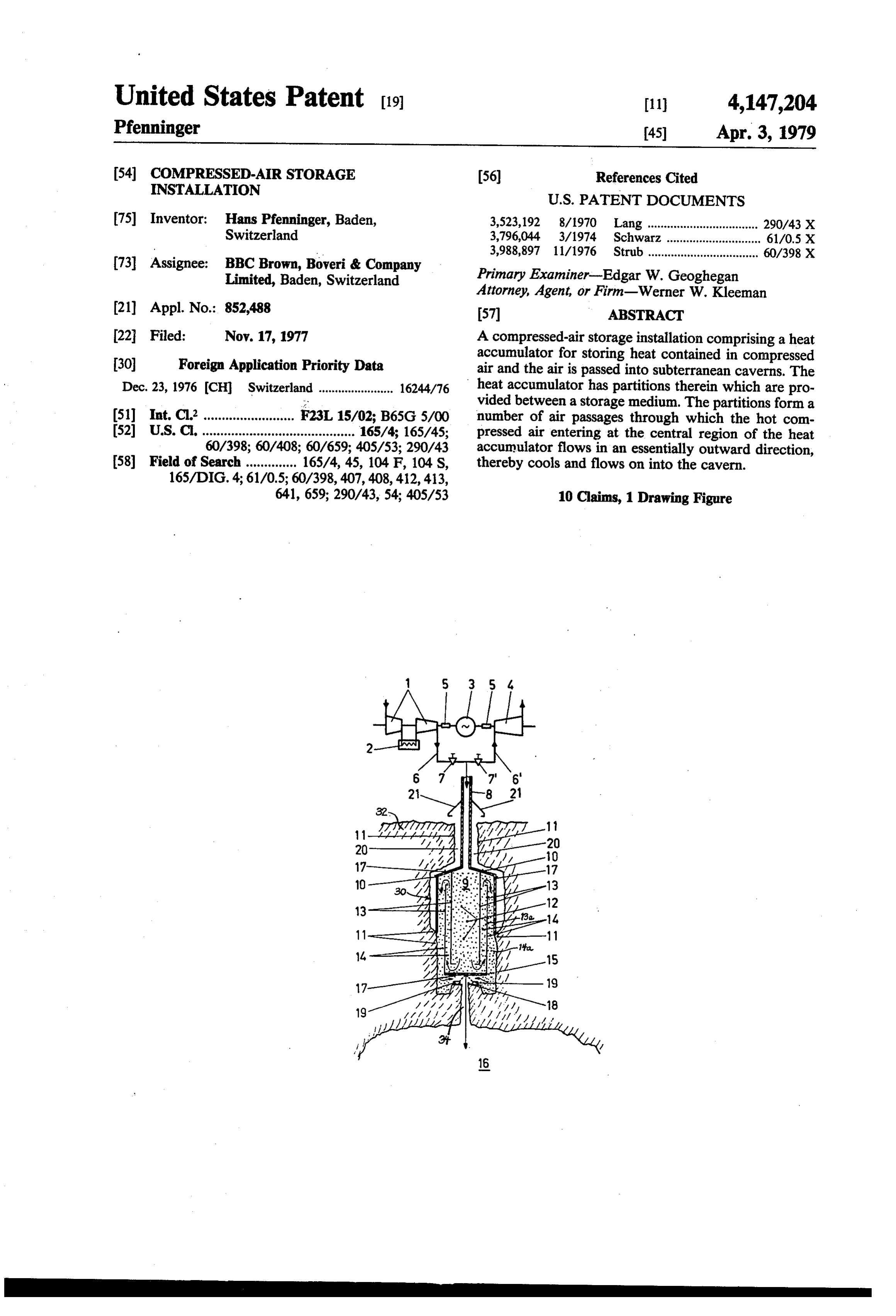
United States Patent (19) 11 4,147,204 Pfenninger 45) Apr. 3, 1979 54 COMPRESSED-AIRSTORAGE (56) References Cited
NSTALLATION
75) Inventor: Hans Pfenninger, Baden, 3,523,192 8/1970 Lang.................................. 290/43X Switzerland 3,796,044 3/1974 Schwarz. ... 61/0.5 X 3,988,897 11/1976 Strub .................................. 60/398 X 73 Assignee: BBC Brown, Boveri & Company
Limited, Baden, Switzerland Primary Examiner-Edgar W. Geoghegan
Attorney, Agent, or Firm-Werner W. Kleeman (21) Appl. No.: 852,488 57 ABSTRACT (22 Filed: Nov. 17, 1977 A compressed-air storage installation comprising a heat 30 Foreign Application Priority Data accumulator for storing heat contained in compressed air and the air is passed into subterranean caverns. The
Dec. 23, 1976 (CH) Switzerland....................... 16244/76 heat accumulator has partitions therein which are pro vided between a storage medium. The partitions form a 51) Int, Cl” ......................... F23L 15/02; B65G 5/00 number of air passages through which the hot com 52 U.S.C. .......................................... 165/4; 165/45; pressed air entering at the central region of the heat 60/398; 60/408; 60/659; 405/.53; 290/43 accumulator flows in an essentially outward direction, 58) Field of Search .............. 165/4, 45, 104 F, 104 S, thereby cools and flows on into the cavern.
641, 659; 290/43, 54; 405/.53 10 Claims, 1 Drawing Figure
Lil
aZe
JAZA
Page 2
Drawing sheet — no readable text.
Page 3
in an essentially outward direction, thereby cools and
COMPRESSED-AIRSTORAGE INSTALLATION flows on into the cavern.
One important advantage of the present invention
BACKGROUND OF THE INVENTION resides in the fact that the partition walls or parititions between the storage medium, in particular between
The present invention relates to a new and improved stones, are so arranged that the incoming air is forced to construction of a compressed-air storage installation flow through the storage medium in an outward direc having a heat accumulator for storing heat contained in tion and gives up its heat to the medium. compressed air, with the compressed air being passed According to another advantageous construction of into subterranean caverns. 10 the invention, the air passages are arranged in such a It is already known to employ compressed air instead manner that a rock wall serves as the outer bounding of liquids as a storage medium for storing energy. The surface of the last passage.
state-of-the-art compressed-air storage installations The consequence of this arrangement is that the air store compressed air at times of low load and utilize it at flowing around the partition walls or partitions has times of peak load to generate additional peak load 15 given up the heat contained in it to the storage medium energy. by the time it reaches the rock wall, and hence the rock With these known installations, in order to increase wall remains relatively cool, i.e., attains a maximum the stored energy while the air is expanding, the air is temperature of 40 C. to 80 C. Due to these measures, heated by combustion of liquid or gaseous fuels before there is avoided crumbling of the rock wall due to the entering an expansion turbine. 20 thermal effects, and thus, there is ensured that the un Compared with hydraulic pump storage stations, this derground chamber of the heat accumulator retains its technique has the disadvantage that additional energy in freedom from leaks, in other words remains leak-tight. the form of a fuel is required for the storage of energy. Furthermore, it is advantageous if the partition walls It has also been proposed not cooling the air during 25 are formed of sheet metal and are thermally insulated at the compression process, in order to thereby obtain as places having large temperature gradients or differ high as possible compressor discharge temperature, and ences between the individual air passages. that the compressed air then should be passed into a It has proved to be of special benefit if the aforemen heat accumulator which removes heat from the air. tioned partition walls are provided with thermal insula After the heat is removed, the cold air then can be 30 tion at places with large temperature differences, in stored in a compressed-air store. Before the air expands particular at the hot air inlet into the heat accumulator in the gas turbine it is heated in the same heat accumula and also opposite the outlet from the heat accumulator to the cavern.
tor in the reverse flow direction.
Since the air usually has a pressure of 30 to 60 bar in According to another construction of the invention these known installations, the outlay for storage above 35 there are provided artificially calcined and hardened ground is too great and too expensive. It is for this stones as the storage medium.
reason that there are presently used subterranean cav Through the use of artificially calcined and hardened erns for storing air. Upon leaving the compressor the air stones as a storage medium it is possible to fill the inte rior of the heat accumulator with uniform interstices which is to be stored has a temperature of about 300' C allowing to 500' C. The rock strata forming the cavern will not cined andthe passage of air, because the artificially cal hardened stones can be shaped according to withstand such temperatures, and even a lining of rock of relatively high heat resistance would be costly to requirements.
It has been found to be especially beneficial if in the maintain, especially since additional temperature fluctu heat accumulator of the invention the minimum ratio of ations occur in the heat accumulator during such time as the accumulator length to the accumulator diameter is the storage cavern is being charged and discharged. 45 about 2:1.
SUMMARY OF THE INVENTION It is furthermore advantageous if there is provided Therefore, with the foregoing in mind it is a primary between the same an air inlet pipe and the rock wall surrounding a gap in which, by means of natural air circula object of the present invention to provide an improved tion, the heat compressed-air storage installation which is not associ 50 be removed topassing through the thermal insulation can the outside.
ated with the aforementioned drawbacks and limita tions of the prior art proposals. This avoids heating of the rock outside the central, Another and more specific object of the present in in the hot airrock.
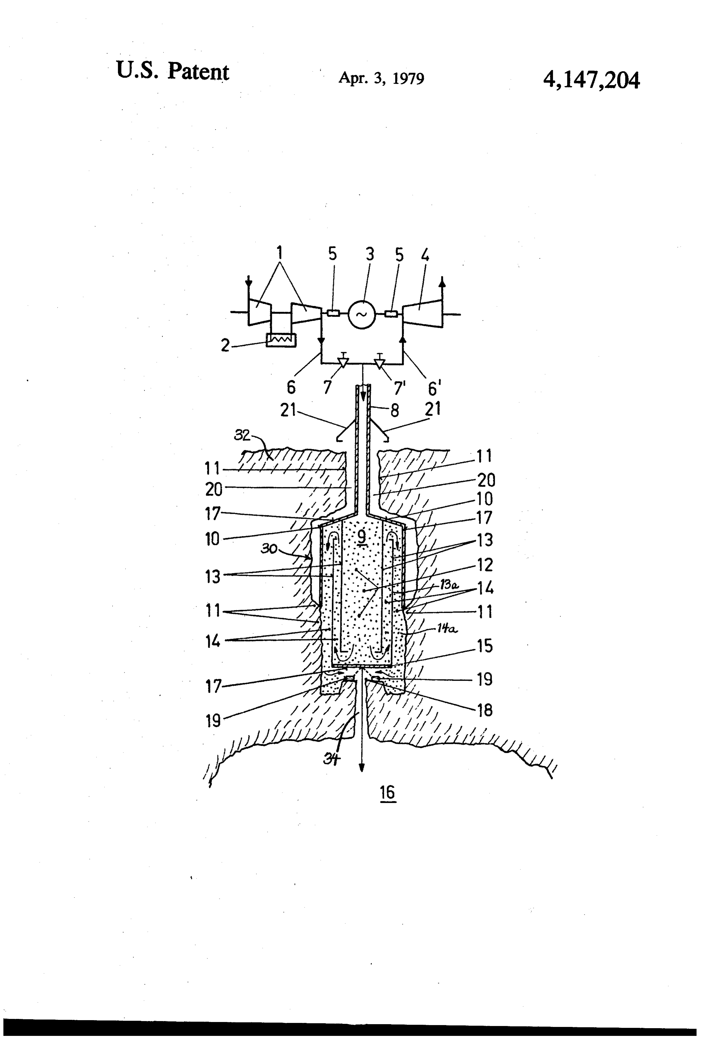
inlet pipe, and the occurrence of thermal stresses vention aims at creating a compressed-air storage instal lation with heat accumulator which is operated without 55 BRIEF DESCRIPTION OF THE DRAWING additional fuel and which is simple and cheap to con The invention will be better understood and objects struct and arranged such that no high temperatures and other than those set forth above will become apparent temperature fluctuations occur in the rock wall. when consideration is given to the following detailed Now in order to implement these and still further description thereof. Such description makes reference objects of the invention, which will become more to the annexed drawing wherein the single FIGURE readily apparent as the description proceeds, the com schematically illustrates, partially in sectional view, a pressed-air storage installation of the present develop compressed-air storage installation constructed accord ment is manifested by the features that partitions are ing to the teachings of the present invention. provided within the heat accumulator between a stor age medium, in particular stones. These partitions or DETAILED DESCRIPTION OF THE partition members form a number of air passages PREFERRED EMBODIMENTS through which the hot compressed air entering at the Describing now the drawing, an exemplary embodi center or central region of the heat accumulator flows ment of the invention is shown schematically and par
Page 4
tially in sectional view in the single FIGURE, wherein and the stop valve 7 in the pipe 6 is open. The air which reference character 1 denotes two compressors between has been compressed and heated in the compressors 1 which there can be located a cooler 2. Between the passes along the pipe 6 and the open stop valve 7 and compressors 1 and one side of a motor-generator 3 and through the insulated pipe 8 into the center or central the other side of the motor-generator 3 and a gas turbine region of the storage medium 12 contained in the subter 4 there are provided couplings 5 by means of which the ranean heat accumulator 9. This air is forced between gas turbine 4 can be selectively coupled with the motor the partition walls or partitions 13 into the air passages generator 3 or the motor-generator 3 can be coupled 14 and thus flows in a generally outward direction, with the compressors 1, as required. Between the gas while giving-up the heat contained in it to the storage turbine 4 and the compressors 1, there are pipes or 10 medium 12. In the last air passage 14a such air flows conduits 6 and 6' which incorporate shutoff elements in downwards between the rock wall 11 and the last parti the form of stop valves 7 and 7", respectively. The pipes tion wall 13a, flows through the heat-loss coolers 19, 6 and 6 are joined to an insulated pipe or conduit 8 where it surrenders any remaining heat, and passes which leads into a subterranean heat accumulator 9. through the air outlet 18 and passage 34 into the com Now the subterranean heat accumulator 9 is prefera 15 pressed-air storage cavern 16.
bly of such a form that it consists of a cavern, generally At times of peak load with additional demand for indicated by reference character 30, cut out of the natu energy, the air stored in the subterranean cavern 16 rally occurring rock32. The insulated pipe or conduit 8 passes upward through the heat accumulator 8, where carries heated air coming from the compressors 1 to the upon it must again flow through the air passages 14, but center or central region of the heat accumulator 9. The 20 in the opposite direction. In doing so it absorbs heat heat accumulator 9 is covered at the top by a cover 10 which has been stored in the storage medium 12 and is connected in any appropriate manner with the insulated led through the insulated pipe 8 and the now open stop pipe 8. It is advantageous if the cover 10 is extended valve 7" in the pipe 6 to the gas turbine 4 which now is further downwards until it encounters a rock wall 11 to coupled to the motor-generator 3 by way of the related which it is anchored, forming a seal in the upward di 25 coupling 5.
rection. The compressed-air storage installation with heat Inside of the subterranean heat accumulator 9 there is accumulator as described above is not restricted to what a storage medium 12, preferably stones or artificially has been shown in the drawing. For example, there can calcined and hardened stones, between which there are be provided a pipe system filled with liquid instead of a arranged the partition walls or partitions 13. Between 30 solid storage medium 12, which may consist of natural the spaced partition walls 13 there are formed air pas stones or of artificially calcined and hardened stones, sages 14 through which the hot air flows in a generally and so forth. Furthermore, not particularly illustrated outward direction, in other words in the direction of the non-return valves could be arranged at the heat-loss indicated arrows. The air passages 14 are provided in coolers 19 so that the compressed air flowing into the such a manner that the last passage, here indicated by 35 cavern 16 is passed through the residual heat coolers 19, reference character 14a, is formed between one of the whereas when the flow is reversed the compressed air partition walls 13 and the rock wall 11. At places with from the cavern 16 by-passes the residual heat coolers particularly large temperature differences, for example 19. Non-return valves of this kind would reduce a rela at the air inlet, i.e., the region where the air travelling tively large drop in pressure of the compressed air. through the insulated pipe 8 enters the heat accumulator 40 While there are shown and described present pre 9, and at a baffle device 15 closing off the cavern 30 of ferred embodiments of the invention, it is to be dis the heat accumulator 9 from a compressed-air storage tinctly understood that the invention is not limited cavern 16, the partition walls 13, the cover or cover thereto, but may be otherwise variously embodied and member 10 and the baffle device 15 are provided with practiced within the scope of the following claims. thermal insulation 17. Located at an air outlet 18 from 45 Accordingly, the heat accumulator 9 into the compressed-air storage What I claim is:
cavern 16 are heat-loss coolers 19 which absorb any 1. A compressed-air storage installation comprising: heat losses still present before the inlet 34 into the com aheat accumulator for storing heat contained in com pressed-air storage cavern 16. pressed air moving through said heat accumulator; Between the insulated pipe 8 carrying air into the at least one subterranean cavern into which there is heat accumulator 9, and also the cover 10 and the rock passed the air moving through the heat accumula wall 11 surrounding the cover 10 and the insulated pipe tor;
8, there is provided a gap or intermediate space 20 a storage medium disposed within said heat accumu where the heat passing through the thermal insulation lator for the storage of the heat of the compressed 17 can be removed to the outside by natural air circula 55 air moving through the heat accumulator; tion. Furthermore, a protective cover 21 is located on partition means arranged in the storage medium for the insulated pipe 8 and this protective cover 21 pre forming a number of air passages through which vents rain or snow from entering the gap or intermedi hot compressed air flows in an essentially outward ate space 20 and hence passing into the heat accumula 60 direction;
tor 9. means for infeeding the hot compressed air to the The compressed-air storage installation with heat heat accumulator;
accumulator as contemplated by the present invention said hot compressed air which flows in an essentially functions in the following manner: outward direction through said air passages cool At times of low load demand, the motor-generator 3 ing due to heat transfer to the storage medium and is coupled by way of coupling 5 to the compressors 1 65 then flowing on into said subterranean cavern. and drives the latter. At the same time, coupling 5 be 2. The compressed-air storage installation as defined tween the motor-generator 3 and the gas turbine 4 is in claim 1, wherein:
disengaged, and the stop valve 7" in the pipe 6 is closed, said storage medium comprises stones.
Page 5
3. The compressed-air storage installation as defined said storage medium comprises artificially calcined in claim 1, wherein: and hardened stones.
said partition means comprises partition walls form 8. The compressed-air storage installation as defined ing a number of said air passages. in claim 1, wherein:
4. The compressed-air storage installation as defined 5 saidlength heat accumulator has a minimum ratio of its to its diameter which amounts to about 2:1.
the partition means forming the air passages are ar in claim 7, wherein: storage installation as defined 9. The compressed-air ranged in a manner such that a rock wall of the said means for infeeding the hot compressed air com cavern serves as an outer bounding surface of the 10 prises an air inlet pipe at least partially surrounded outermost passage of said air passages. by a rock wall;
5. The compressed-air storage installation as defined said air inlet pipe being dispositioned in relation to the in claim 1, wherein: rock wall surrounding it such that there is provided said partition means comprise partition walls formed 15 a gap by means of which through natural air circu of sheet metal. lation the heat passing through the thermal insula 6. The compressed-air installation as defined in claim tion means can be removed to the outside. 5, wherein: 10. The compressed-air storage installation as defined in claim 1, wherein:
said partition walls are provided with thermal insula tion means at places possessing large temperature 20 saidmeans;
heat accumulator is provided with air outlet and differences between the individual air passages. heat-loss cooler means located at the region of said air 7. The compressed-air installation as defined in claim outlet means.
Provenance
- Collection
- Cited prior art
- Original PDF
- patentimages.storage.googleapis.com →
- Filed
- 1977-11-17
- Pages
- 5
- Method
- pdftotext (the PDF's own text layer) + pdftoppm 300dpi page scans
- Source
- Google Patents bibliographic record
- Granted
- 1979-04-03
- Inventors
- Hans Pfenninger; BBC Brown Boveri AG Switzerland
- Transcribed from
- patentimages.storage.googleapis.com →