patent · US2241718
Compressor or vacuum pump
13 May 1941
Page 1
Drawing sheet — no readable text.
Page 2
Patented May 13, 1941 2241,718
UNITED STATES PATENT OFFICE
COMPRESSOR OR WACUUMPUMP
Elmer Peter Meixsell, Allentown, Pa., assignor to
Fuller Company, Catasauqua, Pa., a corpora tion of Delaware
Application April 23, 1940, Serial No. 331,077
This invention relates to rotary air compressors livered to the moving parts. Moreover, in such and pumps which include a stator casing housing apparatus, the lubricating oil has not been de an eccentrically mounted rotor which carries a livered into the air stream in such manner and plurality of sliding vanes making contact cen in such relation to the position of the moving trifugally with the casing wall. More particu parts as to obtain maximum efficiency from the larly, the invention is concerned with a novel lubricant being used and certain of the devices referred to are not susceptible of control of the compressor or pump of the sliding vane type which includes improved means for lubricating amount of lubricant being supplied and are, there the relatively moving parts thereof so that the fore, unreliable in operation and likely to be apparatus is adapted for high speed and high 0 uneconomical.
pressure operation. The present invention is, accordingly, directed Compressors and pumps of the sliding vane to the provision of a novel compressor or vacuum type have been used for many years and the pump of the sliding vane type in which means problem of lubricating the vanes has become in are provided for delivering controlled quantities of lubricant to the moving parts with uniform dis creasingly difficult of solution with the demands tribution for machines capable of operation at higher of the lubricant thereon. The desired speeds and pressures. In the operation of such Supply result is obtained by making use of a lubricant a machine, the vanes, which are mounted in slots ing within means which has a discharge orifice ly in the rotor, move in and out as the latter rotates the incoming air stream, and is so and unless the vanes are covered with a thin film 20 Constructed that the lubricant being delivered is of oil over their entire surfaces, they become ex form atomized and thus entrained by the air in the tremely hot and are likely to stick in the slots. of a fine mist or spray. The position of Also, if the lubrication is incomplete or non the discharge is such as to insure the delivery of uniform, the outward movement of the vanes lubricant to the vanes as they approach their after they pass the point of nearest approach to 25 Outermost positions and the supply is under posi tive control so that only such amount of lubri the stator Wall may be delayed momentarily after which, the vanes move outward very rapidly and cant is used as is required and waste is thereby strike the stator wall with great violence. If the avoided.
vanes are made of a hard material, such as theThe new compressor and vacuum pump include Swedish steel, the continued hammering action 30 boreusual stator casing provided with a central having one or more air inlets on one side and referred to forms longitudinal ridges in the stator an air outlet on the other side. The bore is wall, while if the vanes are made of a synthetic cylindrical and within it is eccentrically mounted resin or like material, the outer edges of the a rotor having radial slots in which are mounted vanes are damaged by the hammering. In either sliding vanes. The eccentricity of the mounting . . case, the efficiency of the apparatus is impaired. 35 of the rotor is such that at one point between Various attempts have been made heretofore to lubricate the vanes and stator walls of these the inlet and outlet ports, the surface of the machines, as, for example, the Pfeiffer Patent No. androtor lies close to the inner wall of the stator 1,890,003 discloses the introduction of lubricant with this arrangement, there is a crescent at the base of the rotor slots in controlled 40 shaped space between the rotor and stator which is Subdivided into compartments by the vanes.
amounts. While this method of lubrication is satisfactory in devices operating at low speeds The lubricant is delivered into the incoming and pressures, it is inadequate and expensive air stream by a quill discharge device so con when used in high speed and pressure apparatus. Structed that the lubricant discharged therefrom It is also objectionable in that its use necessitates is atomized by the air and picked up and carried the provision of special means for removing ex along thereby. The inlet port in the apparatus cess lubricant. For this purpose, grooves lead posed is eccentric relative to the rotor axis, being dis ing to the discharge port are formed in the stator on the side of the axis opposite to the wall, but such grooves produce serious wear on Seal, and the discharge point for the oil is at the the Vanes, so that frequent replacement is re 50 Side Seal.
of the axis of the inlet port opposite to the
The incoming air stream carrying the lubri quired. Moreover, in common with other meth ods of lubrication, the patented system does not cant, accordingly, impinges upon the vanes as produce uniform distribution of the oil, so that they are more or less exposed beyond the slots uneconomical quantities of the latter must be and the oil comes in contact with the entire ex employed. ' . . . . 55 posed portions of the vanes as the rotor rotates. Another expedient that has been proposed in The vanes returning to the innermost positions volves utilizing the incoming air as a carrier for carry the oil therewith and the surfaces of the the lubricant, but the prior apparatus of this type Vanes and the walls of the slots are thereby . with which I am familiar has not been successful covered with a film of the lubricating material. because the lubricant has not been uniformly de 60 For a better understanding of the invention,
Page 3
reference may be had to the accompanying draw to supply an excess of oil until the parts become
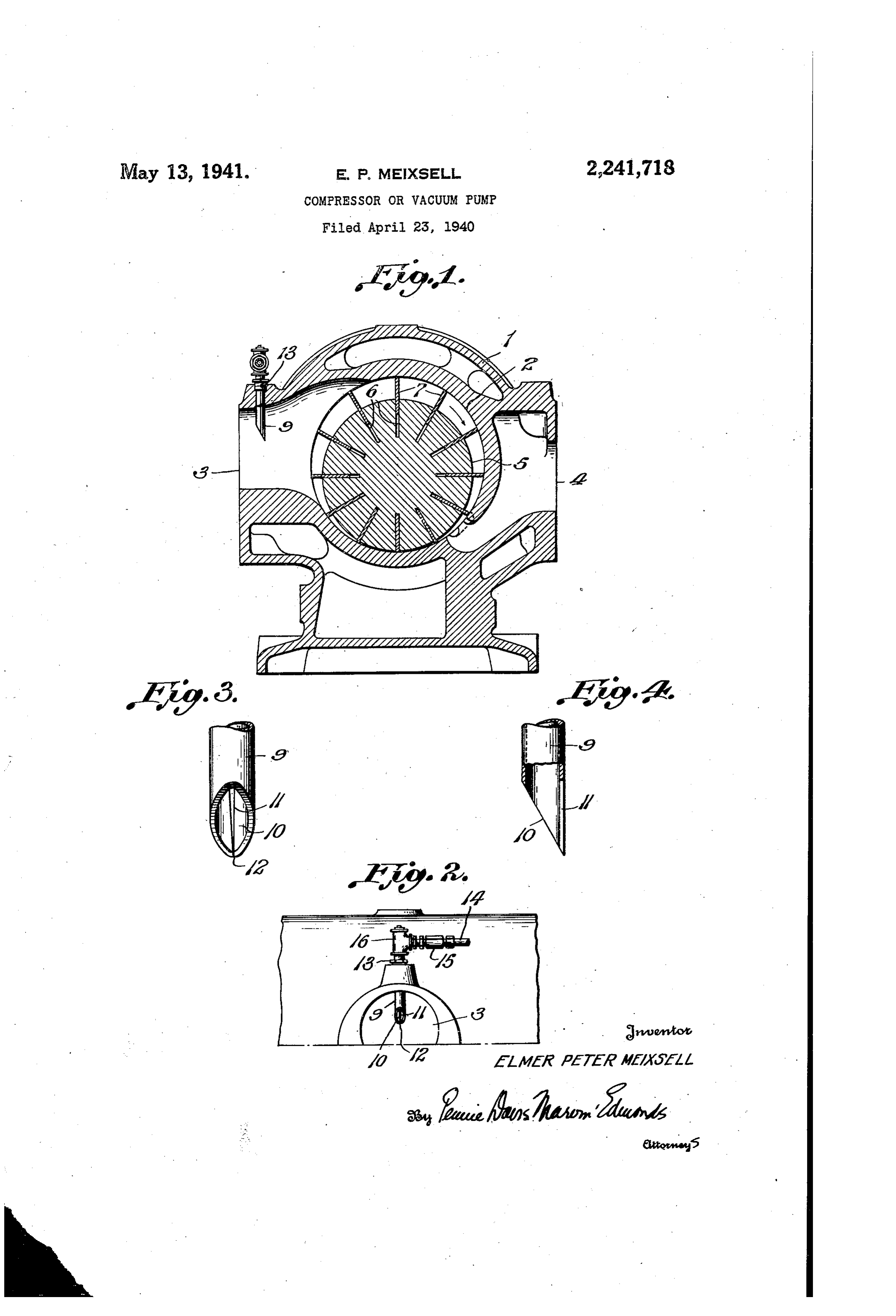
Fig. 1 is a view in transverse section of one well lubricated, after which the feed is cut down form of the apparatus embodying the invention; and throughout the remainder of the operation, Fig. 2 is a fragmentary elevation of the inlet the oil is Supplied in the Small amounts indi side of the apparatus; cated. Because of the small quantity of oil re Fig. 3 is a view in elevation of the end por quired with the new device, it is unnecessary to tion of the lubricating tube; and provide means for taking care of excess lubri cant.
Fig. 4 is an elevational view, partly in section, at right angles to Fig. 3. I claim:
0. 1. A rotary compressor comprising a stator
The machine illustrated in the drawing com prises a stator casing f having a cylindrical bore providedhaving casing with a central bore, a cylindrical rotor radial slots, vanes slidable within 2 and air inlet and outlet openings 3 and 4 on the slots, the rotor being arranged eccentrically opposite sides of the bore. A rotor 5 is mounted eccentrically Within the bore and has a plurality 5 Within the bore between heads at each end of the casing, thereby forming a seal between the of radial slots 6 in which are mounted sliding inner casing Wall at One point and a crescent Vanes . The eccentric mounting of the rotor shaped space opposite the Seal, Said casing hav Withirt the bore is such that the Surfaces of the ing a passage at that side of the rotor where the rotor and the wall of the bore lie so close together Crescent shaped Space is increasing in magni at one point as to form an air seal in accordance 20. tude, in the direction of rotation of the rotor, Said With the usual practise. The air inlet port com passage terminating in an inlet port for said Cres municates with the Crescent-shaped air space be cent shaped space continuously communicating tween the Wall of the bore and the surface of the therewith at Substantially its point of greatest rotor remote from the seal, and the axis of the port is on the side of the axis of the rotor op 25 magnitude, said casing having an outlet port on the opposite side, lubricating means within Said posite to the seal. The air entering the port thus passes directly to the crescent-shaped passage having its outlet spaced from the walls chamber and impinges upon the side of the thereof and to the side of the longitudinal axis Vanes while they are moving outward. Of the passage adjacent the point of maximum magnitude of the Crescent shaped Space, whereby
Mounted in an opening through the wall of lubricant is atomized by the incoming gases paSS the inlet port and extending into the interior 30 ing through said passage and continuously is of the port is a lubricator 9 which may con carried to the Crescent shaped Space and depos Veniently take the form of a tube having its low ited on the back of the vanes when said vanes er end cut off at an angle to its axis to provide are positioned at Substantially their point of an elliptical opening 10 which faces the incom ing air. In the Wall opposite the opening is a 35 maximum extension.
2. A rotary compressor comprising a stator
V-shaped orifice f f which may be formed by cut casing having a central bore, a cylindrical rotor ting a lengthwise slot in the wall of the tube and provided with radial slots, vanes slidable with forcing the end walls of the slot together, as indicated at 2. The lubricator tube is held in 40 trically withinthe in the slots, rotor being arranged eccen the bore between heads at each place in any suitable manner as by a nut 3 and it is Supplied with lubricant through a line 4 end of the casing, thereby forming a Seal be tween the inner casing Wall at One point and a
Which communicates With the tube 9 through a Crescent shaped space opposite the seal, said check valve 5 and a suitable fitting 6. The casing having a passage at that side of the rotor lubricant is forced through the line 4 by any Where the crescent shaped space is increasing in Suitable feed device which can be controlled and magnitude, in the directition of rotation of the the check valve is employed to prevent escape rotor, said paSSage terminating in an inlet port ofInairthe or gas backward into the line 4.
operation of the apparatus, the lubri for said crescent shaped space continuously communicating therewith at substantially its cant flows down the inner wall of the tube 9 50 point of greatest magnitude, the passage having into the path of that portion of the air stream its longitudinal axis substantially perpendicular Which enters the Opening 0 and escapes through to a plane through the longitudinal axis of the the opening . Because of the relatively small rotor and the point of maximum magnitude of size of opening ill, air pressure is built up on the the crescent shaped space and the axis of the incoming Side thereof and the oil or other lubri 55 passage being positioned to the side of the longi cant employed is forced through opening and tudinal axis of the rotor adjacent the crescent atomized. As a result of the increased velocity shaped Space, said casing having an outlet port which the air flowing through opening at on the opposite side, lubricating means within tains, the atomized oil is dispersed throughout the passage having its outlet space substantially the air stream and is thus distributed on the
Vanes, rotor, and inner cylinder bore. 60 midway between the wall thereof and the longi It Will be observed that the lower end of the tudinal axis of the passage at the side of the lubricator 9 lies above the axis of the port 3 paSSage adjacent the crescent shaped space, said and preferably the center of the opening O lies lubricating means comprising a tubular conduit approximately half way between that axis and terminating in an elliptical opening formed by the upper Wall of the port. With this arrange 65 cutting the tubular conduit at an acute angle to ment, the lubricant is properly distributed on its longitudinal axis, a narrow longitudinal air the desired Surfaces and important savings in passa'eway in the wall of the tube opposite the elliptical opening extending from a point ad lubricant are effected. Thus, one type of Com jacent its extremity, whereby lubricant is atom pressor provided with the new lubricating device 70 ized by the incoming gases passing through said requires four drops of oil per minute, While a passage and continuously is carried to the cres compressor of the Pfeiffer type, Operated under cent shaped Space and deposited on the back of Y the same conditions, requires eighteen drops of the vanes when said vanes are positioned at lubricant per minute. At the start of Operations Substantially their point of maximum extension. of the new device, the feed is ordinarily adjusted 5 EIMER PETER MEXSELL,
Provenance
- Collection
- Cited prior art
- Original PDF
- patentimages.storage.googleapis.com →
- Filed
- 1940-04-23
- Pages
- 3
- Method
- pdftotext (the PDF's own text layer) + pdftoppm 300dpi page scans
- Source
- Google Patents bibliographic record
- Granted
- 1941-05-13
- Inventors
- Meixsell Elmer Peter; Fuller Co
- Transcribed from
- patentimages.storage.googleapis.com →