patent · US4611857
Solar powered focusing and directing apparatus for cutting, shaping, and polishing
16 September 1986
Page 1 — bibliographic record
United States Patent (19) 11 Patent Number: 4,611,857 Watkins 45 Date of Patent: Sep. 16, 1986 (54). SOLAR POWERED FOCUSING AND Primary Examiner-Stephen J. Novosad DIRECTING APPARATUS FOR CUTTING, Assistant Examiner-Thomas J. Odar SHAPING, AND POLISHING Attorney, Agent, or Firm-Albert Watkins 76) Inventor: Ivan W. Watkins, 1530 Kilian Blvd., (57) ABSTRACT St. Cloud, Minn. 56301 (21) Appl. No.: 635,445 A solar powered cutting, shaping, and polishing device is disclosed. In the preferred embodiment a large con 22 Filed: Jul. 30, 1984 cave parabolic reflector is mounted on an X and Y axis 51) Int. Cl. ................................................ E21B 7/14 rotatable (telescope type) mount and directed towards (52) U.S. C. ...................................... 299/14; 350/620; the sun. A smaller convex parabolic reflector is 299/10 mounted on an adjustable support structure attached to 58) Field of Search ...................... 299/10, 14; 175/11, the large concave reflector such that the two reflectors 175/12, 13, 14, 15, 16; 350/505, 567,568, 620; can be made to share, or nearly share, the same focal 237/1 R point. Mounted between the large and small parabolic reflectors on an additional rotatable mount is a flat re 56) References Cited flector. The large and small parabolic reflectors are
3,532,410 2/1968 La Roche ....................... 350/505 X able focal point. The flat reflector can then be used to 3,544,165 4/1967 Snedden .............. ... 175/16 X direct the concentrated energy across a material in an 4,066,138 1/1978 Salisbury et al. ... ... 299/14 X operator-determined pattern. Depending on certain 4,090,572 5/1978 Welch ................. ... 299/14 X factors associated with the material and the positioning 4,270,844 6/1981 Cobble et al. ....................... 350/620 of the focal point, the material can then be cut, shaped, 4,395,095 7/1983 Horton ............................ 350/567 X or polished as the user desires. Also disclosed is the use
OTHER PUBLICATIONS of lenses to perform the concentrating function. Wyatt, Stanley P., Principles of Astronomy, Allyn and
Bacon, Inc., Boston, 1964, pp. 103-104. 19 Claims, 4 Drawing Figures
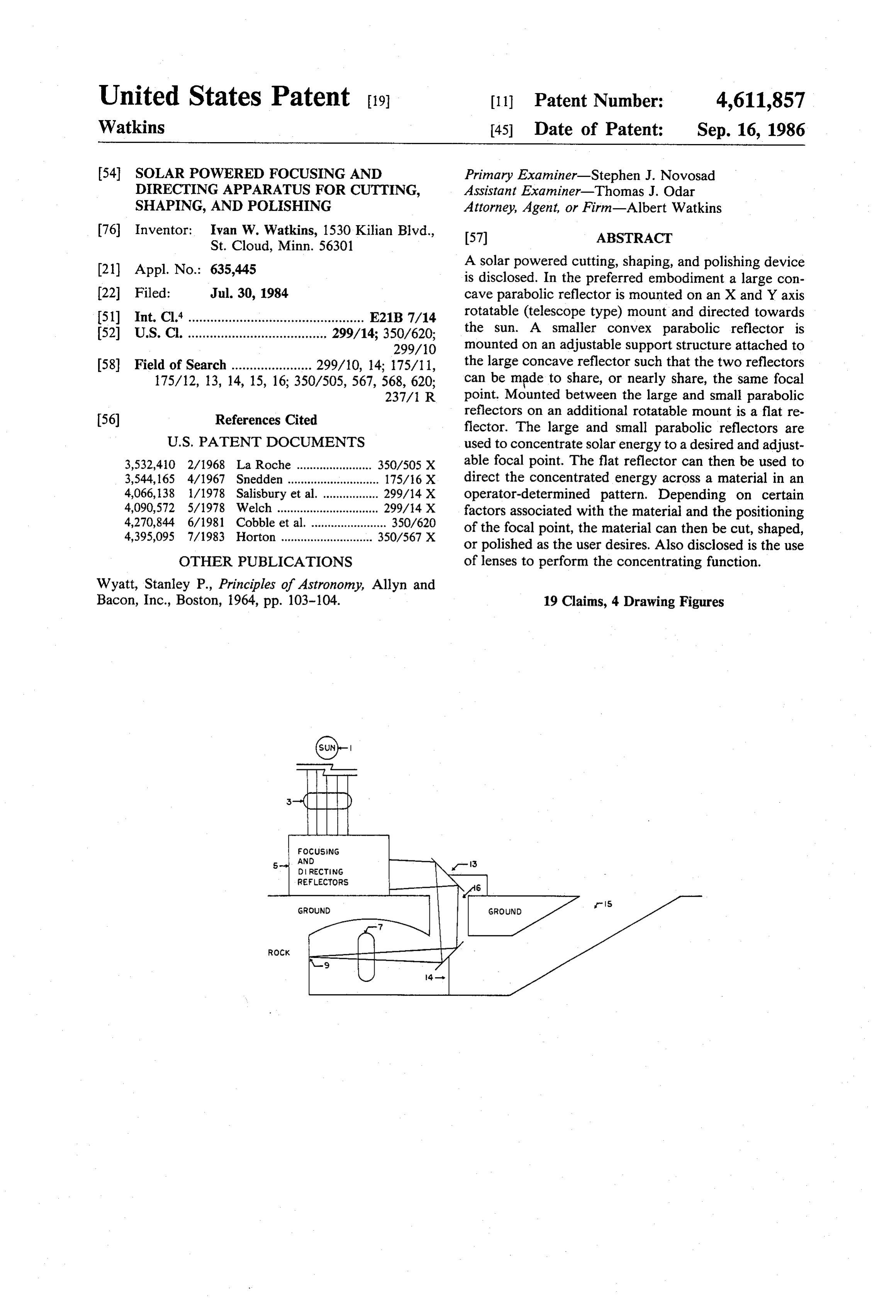
FOCUSING
AND
DIRECTING
RefLECTORS
GROUND
Page 2
Drawing sheet — no readable text.
Page 3
Drawing sheet — no readable text.
Page 4
Drawing sheet — no readable text.
Page 5
Drawing sheet — no readable text.
Page 6
radiation while simultaneously cutting, shaping, or pol
SOLAR POWERED FOCUSING AND DIRECTING ishing materials.
APPARATUS FOR CUTTING, SHAPING, AND These and other objects are achieved through the use POLISHING of a focusing and directing apparatus which controlla bly concentrates and directs solar radiation to a material
BACKGROUND OF THE INVENTION where, depending upon characteristics of the material Prior art cutting, shaping, and polishing techniques and the degree of focus, cutting, shaping, or polishing generally fall into three broad categories including may be performed. The applications of such an appara guided or unguided cracking, abrasive forming, and 10 tus include metalwork, rock work, road and tunnel localized heating. building, and mining to name only a few possibilities. Cracking may be done without an external guide, for BRIEF DESCRIPTION OF THE DRAWINGS example by following internal faults or, depending on the material, by following a cleavage plane. Guided FIG. 1 shows the preferred embodiment of the pres cracking may be done in the case of rock by predrilling 15 ent invention.
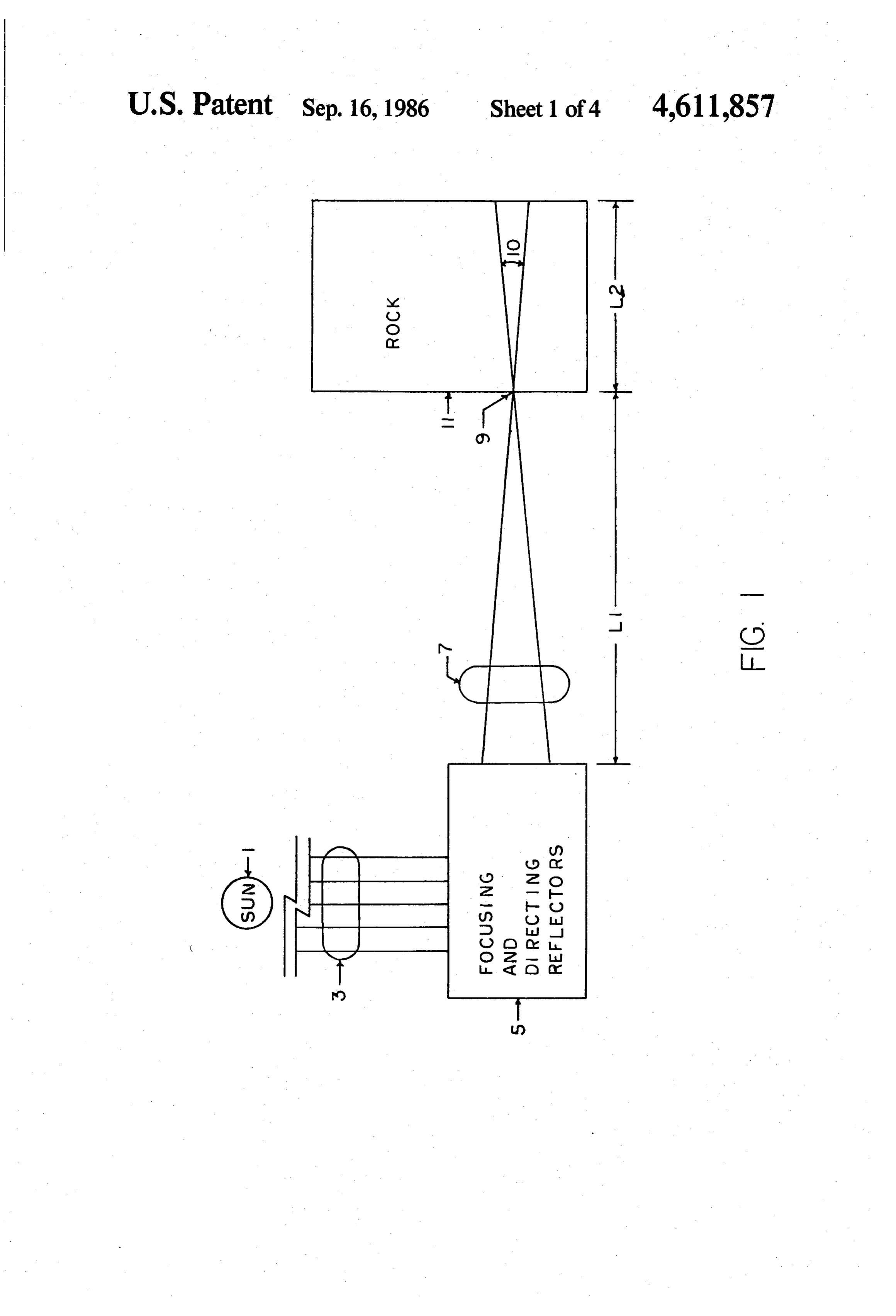
to create weak spots and then cracking between the FIG. 2 shows the preferred embodiment of the pres drilled holes another example of guided cracking is ent invention as applied to mine shaft operation or road tunnel.
glass cutting, where a weak line is formed by a glass FIG. 3 shows the focusing and directing apparatus of Cutter.
the
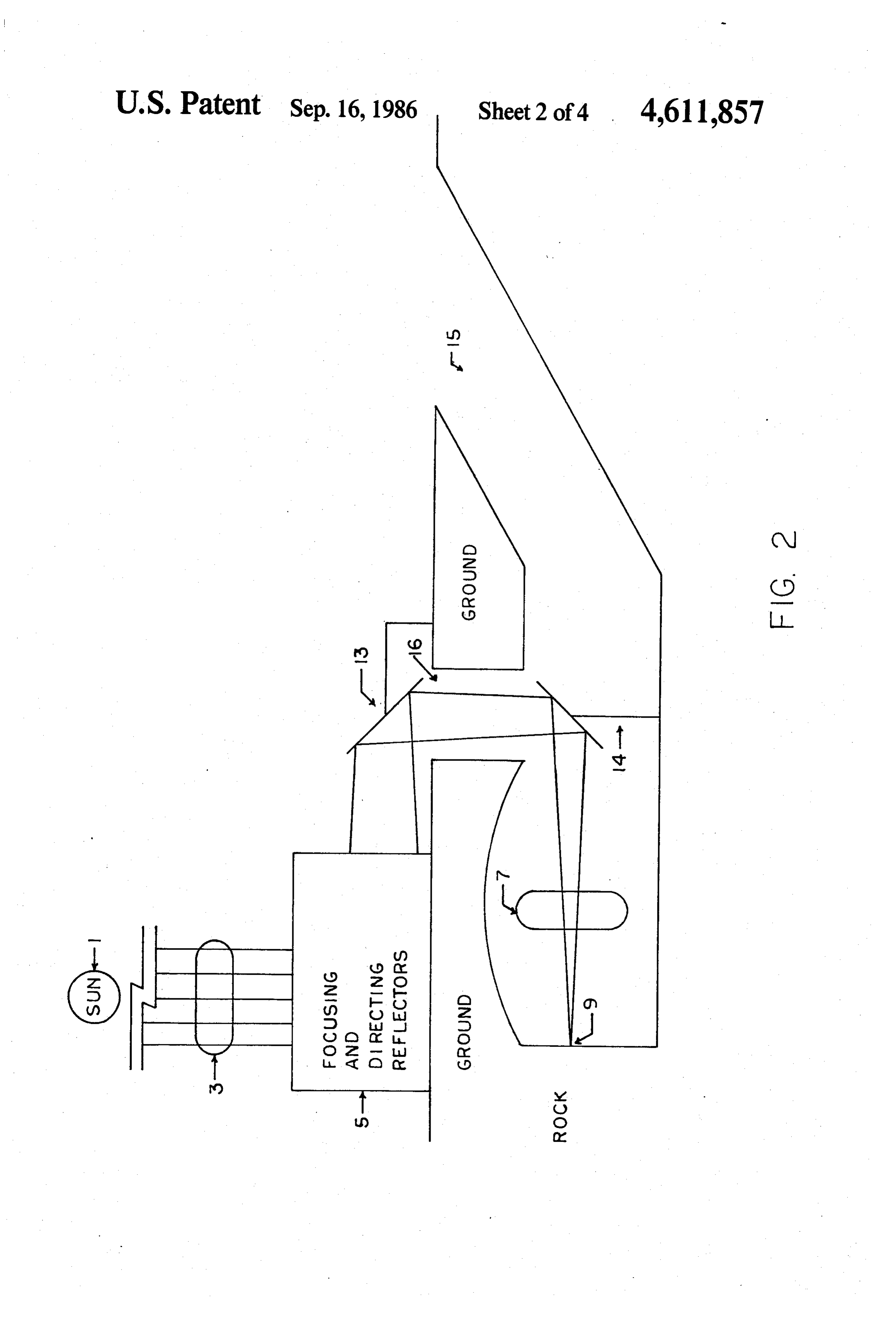
Abrasive forming is perhaps the most commonly used 20 FIG. preferred embodiment.
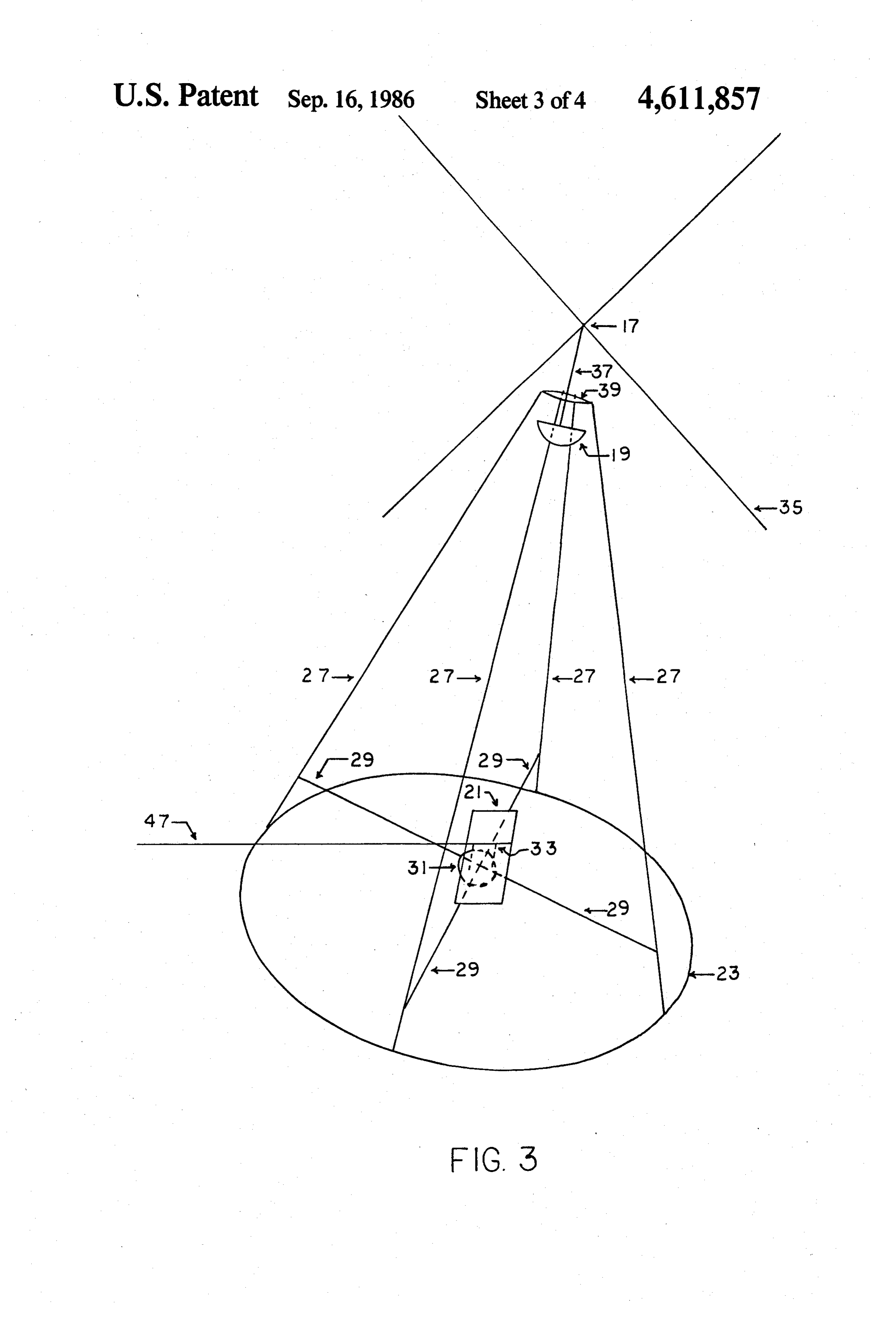
cutting, shaping and polishing technique. Included in 4 shows the focusing and directing apparatus in this category are sawing, drilling, sanding, grinding, operation, with all support structure removed for clar buffing and other techniques which are too numerous to ity.
mention. DETAILED DESCRIPTION OF THE Localized heating is often used in cutting and shaping 25 INVENTION metals by melting such as with a torch. Cutting of rock such as granite is also often done this way, by using a invention and its bestthemode
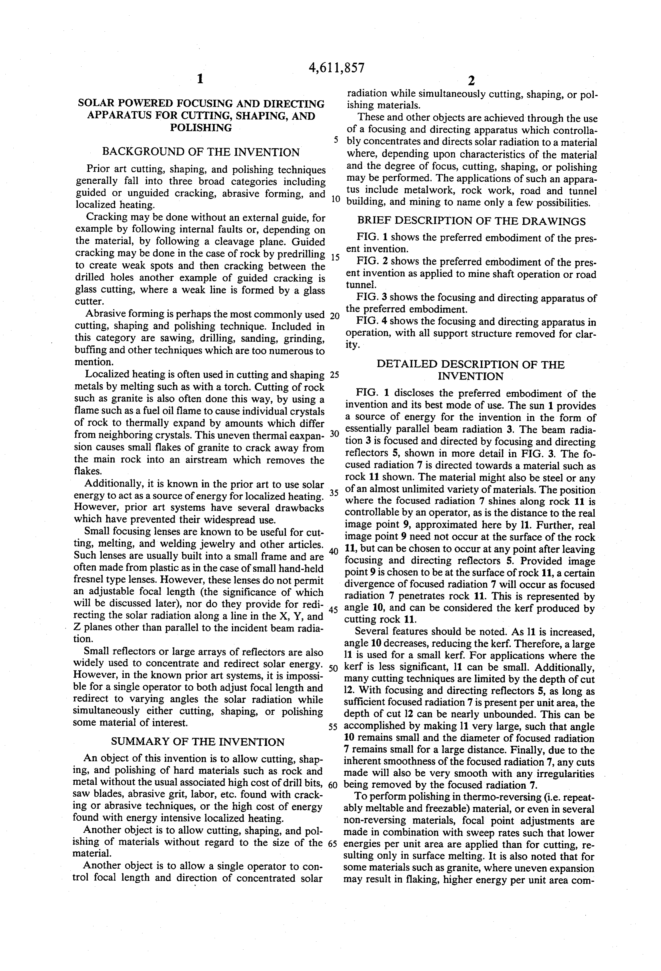
FIG. 1 discloses preferred embodiment of the flame such as a fuel oil flame to cause individual crystals a source of energy for the ofinvention use. The sun 1 provides in the form of of rock to thermally expand by amounts which differ essentially parallel beam radiation 3. The beam radia from neighboring crystals. This uneven thermal eaxpan 30 tion 3 is focused and directed by focusing and directing sion causes small flakes of granite to crack away from reflectors 5, shown in more detail in FIG. 3. The fo the main rock into an airstream which removes the cused radiation 7 is directed towards a material such as flakes.
rock 11 shown. The material might also be steel or any
Additionally, it is known in the prior art to use solar 35 of energy to act as a source of energy for localized heating. an almost unlimited variety of materials. The position However, prior art systems have several drawbacks where the focused radiation 7 shines along rock 11 is which have prevented their widespread use. controllable by an operator, as is the distance to the real Small focusing lenses are known to be useful for cut imageimage point 9, approximated here by 11. Further, real ting, melting, and welding jewelry and other articles. 11, butpoint 9 need not occur at the surface of the rock Such lenses are usually built into a small frame and are focusing and chosen can be to occur at any point after leaving directing reflectors 5. Provided image often made from plastic as in the case of small hand-held point 9 is chosen to be at the surface of rock 11, a certain fresnel type lenses. However, these lenses do not permit an adjustable focal length (the significance of which divergence radiation 7 of focused radiation 7 will occur as focused penetrates rock 11. This is represented by will be discussed later), nor do they provide for redi 45 angle 10, and can be considered the kerf produced by recting the solar radiation along a line in the X, Y, and cutting rock 11.
Z planes other than parallel to the incident beam radia Several features should be noted. As 11 is increased, tion.
angle 10 decreases, reducing the kerf. Therefore, a large
Small reflectors or large arrays of reflectors are also 11 is used for a small kerf. For applications where the widely used to concentrate and redirect solar energy. 50 kerf is less significant, 11 can be small. Additionally, However, in the known prior art systems, it is impossi many cutting techniques are limited by the depth of cut ble for a single operator to both adjust focal length and 12. With focusing and directing reflectors 5, as long as redirect to varying angles the solar radiation while sufficient focused radiation 7 is present per unit area, the simultaneously either cutting, shaping, or polishing depth of cut 12 can be nearly unbounded. This can be some material of interest. 55 accomplished by making 11 very large, such that angle SUMMARY OF THE INVENTION 10 remains small and the diameter of focused radiation 7 remains small for a large distance. Finally, due to the
An object of this invention is to allow cutting, shap inherent smoothness of the focused radiation 7, any cuts ing, and polishing of hard materials such as rock and made will also be very smooth with any irregularities metal without the usual associated high cost of drill bits, 60 being removed by the focused radiation 7. saw blades, abrasive grit, labor, etc. found with crack To perform polishing in thermo-reversing (i.e. repeat ing or abrasive techniques, or the high cost of energy ably meltable and freezable) material, or even in several found with energy intensive localized heating. non-reversing materials, focal point adjustments are Another object is to allow cutting, shaping, and pol made in combination with sweep rates such that lower ishing of materials without regard to the size of the 65 energies per unit area are applied than for cutting, re material. sulting only in surface melting. It is also noted that for Another object is to allow a single operator to con some materials such as granite, where uneven expansion trol focal length and direction of concentrated solar may result in flaking, higher energy per unit area com
Page 7
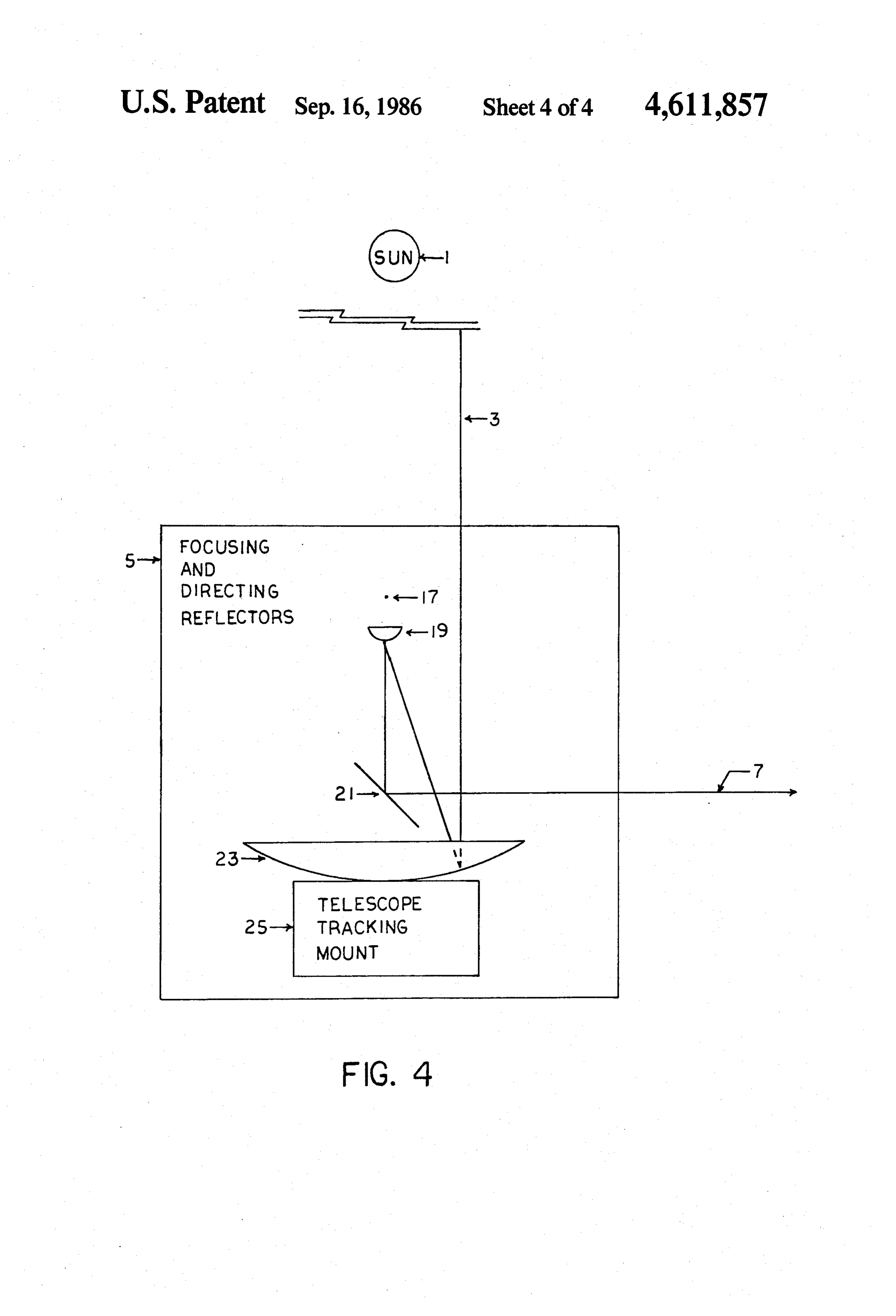
bined with a high sweep rate may be required to melt rected by reflector 21. Telescope tracking mount 25 is the surface before flaking can occur. any one of a number of commercially available tracking FIG. 2 discloses typical application of the preferred mounts, also described by Wyatt, PP. 103-4. Mount 25 embodiment to a mine shaft. It applies equally to the assures continuous focusing of beam radiation 3. After formation of a road tunnel. The sun 1 provides essen assembly of focusing and directing reflectors 5 reflec tially parallel beam radiation 3 to the focusing and di tors 19 and 23 should share focal point 17 (properly recting reflectors 5 which provide focused radiation 7 aligned). This is equivalent to an image distance 11 of for use in cutting, shaping and polishing operations. infinity. The operator then sets the image distance 11 to Focused radiation 7 is directed to the large adjustable a desired distance by rotating adjuster 35. This results in flat reflector 13. The reflectors 13 and 14 are rotatable 10 rotation of threaded rod 37 through the threaded hole in through two axes on a mount such as the telescope plate 39. The net result is a raising or lowering of reflec mounting disclosed by Wyatt in Principles of Astronomy, tor 19 changing the image distance 11. It is advised that 1964, P. 103. Once focused radiation 7 is directed to the an additional stop be provided such that rod 37 can not first reflector 13, reflector 13 is then adjusted to direct be rotated beyond a point where the image distance 11 focused radiation 7 into a mine shaft 15 towards a sec 15 approaches zero. This can be done by stripping the ond reflector 14. Reflector 14 is then used to direct the threads on rod 37 at the appropriate point. This is to focused radiation 7 as desired to perform cutting, shap prevent focusing too much radiation onto too small a ing, and polishing. As shown, ventilation shaft 16 is used point of reflector 21, which could cause burned spots on to conduct focused radiation 7 into mine shaft 15. This reflector 21. As the operator selects image distance 11, is thought to provide an extra safety factor since main 20 The operator simultaneoulsy directs the radiation by entrance 15 is then left completely open to access. Fo either rotating adjuster 47 in the holes of vertical rods cused radiation 7 could similarly be directed near the 33, which raises or lowers focused radiation 7, or by ceiling of mine shaft 15 through the main entrance. rotating the entire apparatus (47,33,21, and top plate of These safety precautions are similar to industrial laser 31) on the lazy susan 31, which moves focused radiation safety practice. While additional reflectors 13 and 14 25 7 back and forth. Connecting rods 27 form natural stops are required, it is noted that the focal length can be very for adjuster 47, preventing reflector 21 from being di large since the extra reflectors provide a long path for rected towards connecting rods 27. Additionally, lazy focused radiation 7. Reflectors 13 and 14 can addition susan 31 forms a natural stop preventing reflector 21 ally be used above ground, where insufficient space is from being directed towards reflector 23. Finally, an available otherwise, to gain extra focal length. 30 additional stop could be mounted on lazy Susan 31 in the
FIG. 3 discloses the preferred embodiment of the form of a vertical rod to prevent reflector 21 from being focusing and directing reflectors 5. Large parabolic directed towards reflector 19. concave reflector 23 is attached to the four connecting The materials used for assembly are not critical so rods 27. The proposed connection is to thread the ends long as, where used for support, they are of sufficient of rods 27, drill four appropriate holes in reflector 23, 35 strength and screw mount one nut on each side (inside and out suggestedtotocarry the load. Reflectors 19,21, and 23 are side) of reflector 23. The use of such attachment allows plate (electroplate, leaf,ofpaint, be made some form of polished gold ...), due to the excellent preliminary alignment. However, any common method reflectivity of gold at the wavelengths of interest and to of attachment is sufficient provided reflectors 23 and 19 the excellent resistance to aging and weathering are in proper alignment to be discussed later. Connect 40 tion, corrosion, ...) shown by gold. However, any(oxida ing rods 27 are welded to a circular disk of approxi able reflector can be used provided the individualsuit re mately inch plate metal 39. In the center of disk 39 is flectors are not overloaded.
a threaded hole. Through the threaded hole is mounted threaded rod 37. Fixedly attached at one end of rod 37 ingThe power available for cutting, shaping, and polish is adjuster 35. Adjuster 35 is of sufficient length and 45 Forisreflector limited only by the size of the reflectors selected.
4 meters in diameter the available energy shape to be reached by an operator standing next to reflector 23. Fixedly attached at the other end of rod 37 at Asea= level can be approximated as follows:
is small parabolic convex reflector 19. Additionally S=Solar radiation at sea level as 1 Kw/m2 attached to connecting rods 27 are connecting rods 29.
At the center of the "X" formed by rods 29 is a lazy 50 E=Efficiency st90% (5% reflective loss and 5% miscellaneous shading) susan 31. Lazy susan 31 is comprised of a bottom plate which is attached to rods 29, a top plate, and a circular AsP-Power=A'S'East noted, the entire
energy content can be focused to a bearing separating the two plates. Mounted to the top small real image 9.
plate of lazy susan 31 are two vertical rods 33. The rods The foregoing is not intended to be limiting in any 33 have holes in the top which accomodate adjuster 47. 55 way
Fixedly attached to adjuster 47 if flat reflector 21. The ment but rather is presented as the preferred embodi operation of the apparatus of FIG. 3 can be understood lenses could invention of the to enable others. It is noted that be substituted for the reflectors shown, or in conjunction with FIG. 4.
FIG. 4 discloses the apparatus of FIG. 3 with all a combination of lenses and reflectors. However, due to support structure removed for clarity. Additionally, 60 the possibly large size and correspondingly large power FIG. 4 shows the telescope type tracking mount 25 to levels being controlled, the cost and limitations of lenses appear to be greater than those of reflectors. Addition which reflector 23 is mounted. The operation of the ally, where operations require a great distance between system is as follows. The sun 1 provides essentially focusing and directing reflectors 5 and image point 9, or parallel beam radiation 3. Radiation 3 is reflected by where access to reflectors 5 is difficult, as in FIG. 2, it reflector 23 towards focal point 17. When reflectors 19 and 23 are in proper alignment, they share (or nearly isusepossible to set image distancell equal to infinity and a second set of focusing and directing reflectors to share) focal point 17. The net result is a focusing of refocus and redirect incoming radiation. In the case of beam radiation 3. The focused radiation 7 is then di
FIG. 2 this would be accomplished by setting image
Page 8
distance 11 (from FIG. 1) to infinity (or just less than), and directed solar energy wherein adjustment of said and replace reflector 14 with a second set of focusing real image distance by said adjusting means results in a and directing reflectors. This would allow a single oper selection of either cutting, shaping, or polishing of said ator to control both focal length and direction of light material.
from within a mine shaft or road tunnel. Additionally, 5 9. The apparatus of claim 8 wherein said material is a while not discussed, it would be apparent to one of metal or metal alloy.
ordinary skill that, in the event that an excess of energy 10. The apparatus of claim 8 wherein said material is was available, such excess could be controlled either by rock.
shading or some form of misalignment of telescope 11. The apparatus of claim 8 wherein said real image tracking mount 25. 10 distance and said direction are simultaneously adjust I claim: able by a single person.
1. An apparatus for focusing and directing solar en 12. The apparatus of claim 8 wherein said real image ergy comprising means for focusing and directing solar distance and said direction are independently and simul energy, said focusing and directing means having a real taneously adjustable.
image distance, and adjusting means for enabling simul 15 13. The apparatus of claim 12 wherein said real image taneous adjustment of both said real image distance and distance and said direction are independently and simul said direction of focused and directed solar energy. taneously adjustable by a single person, while said sin 2. The apparatus of claim 1 wherein said adjusting gle person is simultaneously performing cutting, shap means further provides control of said real image dis ing, or polishing of said material.
tance independent of said direction. 20 14. The apparatus of claim 8 wherein said focusing 3. The apparatus of claim 2 wherein said adjusting and directing means comprises first focusing means, means further provides control of said direction inde second directing means, and means for rotating said pendent of said real image distance. second directing means about two different axes, said 4. The apparatus of claim 3 wherein said adjusting rotation occurring without corresponding movement of means is fully adjustable by a single person. 25 said first focusing means.
5. The apparatus of claim 1 wherein said focusing and 15. A method for cutting, shaping, and polishing directing means comprises a first concave parabolic comprising the steps of focusing and directing a suffi reflector, a second convex parabolic reflector, and a cient quantity of solar energy at a variable real image third plane reflector. distance and variable direction to enable cutting, shap 6. The apparatus of claim 5 wherein said second re 30 ing, and polishing of a material, adjusting said flector is aligned so as to be, if so adjusted by an adjust variable real image distance to a desired distance ing means, able to share the same focal point as said first while simultaneously either cutting, shaping, or reflector, said adjusting means enabling movement of polishing said material by simultaneously adjusting said second reflector closer to, or further from said first said variable direction to obtain a desired position reflector. 35 and movement of a real image. 7. The apparatus of claim 6 wherein said focusing and 16. The method of claim 15 wherein the step of ad directing means further comprises means for rotating justing is performed by a single person. said third plane reflector about two different axes, said 17. The method of claim 16 wherein said material is rotation occurring without corresponding movement of comprised of rock.
said first reflector. 40 18. The method of claim 16 comprising the additional 8. An apparatus for cutting, shaping, and polishing steps of removing said material which has been cut, and comprising means for focusing and directing a sufficient cutting additional material in a predetermined pattern but not excessive quantity of solar energy to perform which will result in the formation of a road tunnel. the processes of cutting, shaping, and polishing on a 19. The apparatus of claim 1 wherein said focusing material, any of said processes being selectable by an 45 and directing means consists of a first concave parabolic operator at any given instant independent of any possi reflector, a second convex parabolic reflector, and a ble previous selection, said focusing and directing third plane reflector, and wherein said adjusting means means having a real image distance, and adjusting consists of a mechanical moving means for moving said means for enabling simultaneous adjustment of both second reflector and for moving said third reflector. said real image distance and said direction of focused 50 xk sk k xt
Provenance
- Collection
- Cited prior art
- Original PDF
- patentimages.storage.googleapis.com →
- Filed
- 1984-07-30
- Pages
- 8
- Method
- pdftotext (the PDF's own text layer) + pdftoppm 300dpi page scans
- Source
- Google Patents bibliographic record
- Granted
- 1986-09-16
- Inventors
- Ivan W. Watkins
- Transcribed from
- patentimages.storage.googleapis.com →