patent · US4142873
Method and apparatus for cleaning a filter bed
6 March 1979
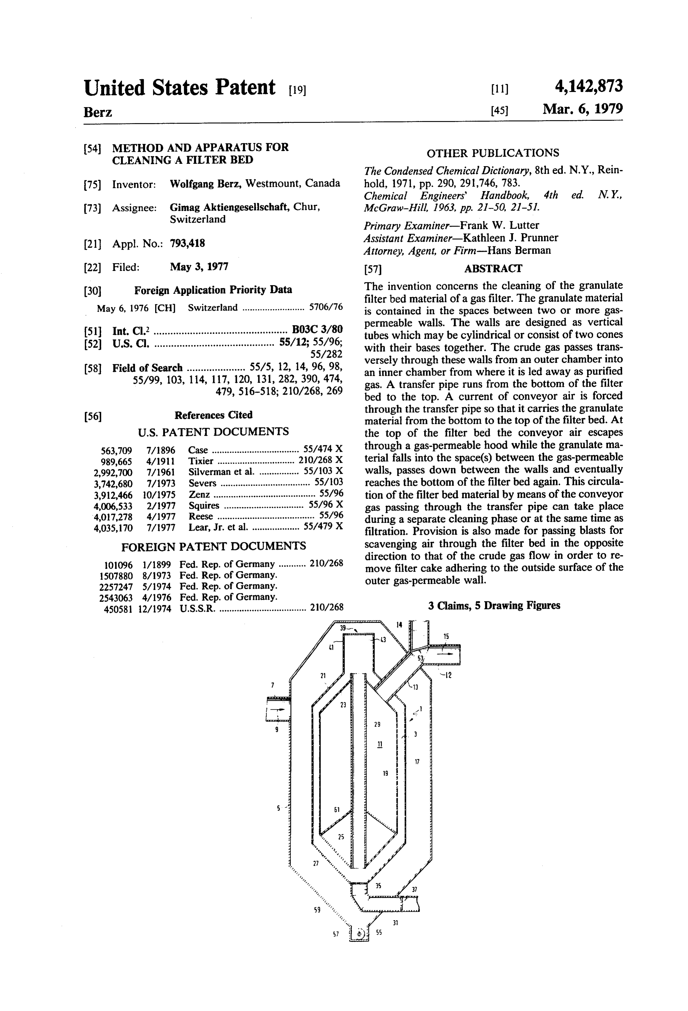
Page 1 — bibliographic record
United States Patent (19) 11) 4,142,873 Berz, 45 Mar. 6, 1979
54 METHOD AND APPARATUS FOR OTHER PUBLICATIONS
CLEANING A FILTER BED
The Condensed Chemical Dictionary, 8th ed. N.Y., Rein 75) Inventor: Wolfgang Berz, Westmount, Canada hold, 1971, pp. 290, 291,746, 783. Chemical Engineers' Handbook, 4th 73) Assignee: Gimag Aktiengesellschaft, Chur, McGraw-Hill, 1963, pp. 21-50, 21-51. Switzerland
Primary Examiner-Frank W. Lutter (21) Appl. No.: 793,418 Assistant Examiner-Kathleen J. Prunner Attorney, Agent, or Firm-Hans Berman (22 Filed: May 3, 1977 57 ABSTRACT (30) Foreign Application Priority Data The invention concerns the cleaning of the granulate filter bed material of a gas filter. The granulate material
May 6, 1976 (CH) Switzerland ......................... 5706/76 is contained in the spaces between two or more gas permeable walls. The walls are designed as vertical 51 Int. Cl. ................................................ B03C 3/80 tubes which may be cylindrical or consist of two cones 52 U.S. C. ........................................... 55/12; 55/96; with their bases together. The crude gas passes trans 55/282 versely through these walls from an outer chamber into 58) Field of Search ..................... 55/5, 12, 14, 96, 98, an inner chamber from where it is led away as purified 55/99, 103, 114, 117, 120, 131, 282,390, 474, gas. A transfer pipe runs from the bottom of the filter 479, 516-518; 210/268, 269 bed to the top. A current of conveyor air is forced 56 References Cited through the transfer pipe so that it carries the granulate material from the bottom to the top of the filter bed. At
563,709 7/1896 Case ................................... 55/474 X through a gas-permeable hood while the granulate ma 989,665 4/1911 Tixier ............... 20/268 X terial falls into the space(s) between the gas-permeable 2,992,700 7/1961 Silverman et al. .. 55/103 X walls, passes down between the walls and eventually 3,742,680 7/1973 Severs .................................... 55/103 reaches the bottom of the filter bed again. This circula 3,912,466 10/1975 Zenz ......................................... 55/96 tion of the filter bed material by means of the conveyor 4,006,533 2/1977 Squires . 55/96 X gas passing through the transfer pipe can take place 4,017,278 4/1977 Reese ....................................... 55/96 during a separate cleaning phase or at the same time as 4,035,170 7/1977 Lear, Jr. et al. ................... 55/479 X filtration. Provision is also made for passing blasts for FOREIGN PATENT DOCUMENTS scavenging air through the filter bed in the opposite 1.01096 1/1899 Fed. Rep. of Germany ........... 210/268 direction to that of the crude gas flow in order to re 1507880 8/1973 Fed. Rep. of Germany. move filter cake adhering to the outside surface of the 2257247 5/1974 Fed. Rep. of Germany. outer gas-permeable wall.
45058 12/1974 U.S.S.R. ................................... 210/268 3 Claims, 5 Drawing Figures
Page 2
Drawing sheet — no readable text.
Page 3
Drawing sheet — no readable text.
Page 4
Drawing sheet — no readable text.
Page 5
Drawing sheet — no readable text.
Page 6
permeable walls, the granulate material subsequently
METHOD AND APPARATUS FOR CLEANING A falling into the space between the gas permeable walls FILTER BED and finally returning between the gas-permeable walls to within the range of influence of the stream of con
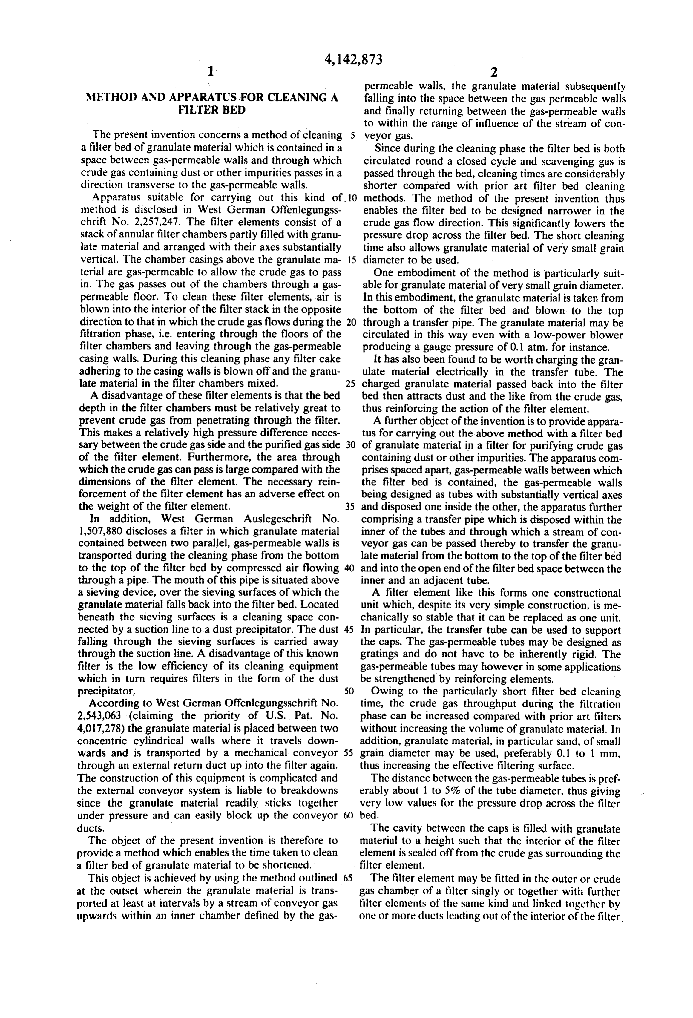
The present invention concerns a method of cleaning 5 veyor gas.
a filter bed of granulate material which is contained in a Since during the cleaning phase the filter bed is both space between gas-permeable walls and through which circulated round a closed cycle and scavenging gas is crude gas containing dust or other impurities passes in a passed through the bed, cleaning times are considerably direction transverse to the gas-permeable walls. shorter compared with prior art filter bed cleaning Apparatus suitable for carrying out this kind of 10 methods. The method of the present invention thus method is disclosed in West German Offenlegungss enables the filter bed to be designed narrower in the chrift No. 2,257,247. The filter elements consist of a crude gas flow direction. This significantly lowers the stack of annular filter chambers partly filled with granu pressure drop across the filter bed. The short cleaning late material and arranged with their axes substantially time also allows granulate material of very small grain vertical. The chamber casings above the granulate ma 15 diameter to be used.
terial are gas-permeable to allow the crude gas to pass One embodiment of the method is particularly suit in. The gas passes out of the chambers through a gas able for granulate material of very small grain diameter. permeable floor. To clean these filter elements, air is In this embodiment, the granulate material is taken from blown into the interior of the filter stack in the opposite the bottom of the filter bed and blown to the top direction to that in which the crude gas flows during the 20 through a transfer pipe. The granulate material may be filtration phase, i.e. entering through the floors of the circulated in this way even with a low-power blower filter chambers and leaving through the gas-permeable producing a gauge pressure of 0.1 atm. for instance. casing walls. During this cleaning phase any filter cake It has also been found to be worth charging the gran adhering to the casing walls is blown off and the granu ulate material electrically in the transfer tube. The late material in the filter chambers mixed. 25 charged granulate material passed back into the filter A disadvantage of these filter elements is that the bed bed then attracts dust and the like from the crude gas, depth in the filter chambers must be relatively great to thus reinforcing the action of the filter element. prevent crude gas from penetrating through the filter. A further object of the invention is to provide appara This makes a relatively high pressure difference neces tus for carrying out the above method with a filter bed sary between the crude gas side and the purified gas side 30 of granulate material in a filter for purifying crude gas of the filter element. Furthermore, the area through containing dust or other impurities. The apparatus com which the crude gas can pass is large compared with the prises spaced apart, gas-permeable walls between which dimensions of the filter element. The necessary rein the filter bed is contained, the gas-permeable walls forcement of the filter element has an adverse effect on being designed as tubes with substantially vertical axes the weight of the filter element, 35 and disposed one inside the other, the apparatus further In addition, West German Auslegeschrift No. comprising a transfer pipe which is disposed within the 1,507,880 discloses a filter in which granulate material inner of the tubes and through which a stream of con contained between two parallel, gas-permeable walls is veyor gas can be passed thereby to transfer the granu transported during the cleaning phase from the bottom late material from the bottom to the top of the filter bed to the top of the filter bed by compressed air flowing 40 and into the open end of the filter bedspace between the through a pipe. The mouth of this pipe is situated above inner and an adjacent tube.
a sieving device, over the sieving surfaces of which the A filter element like this forms one constructional granulate material falls back into the filter bed. Located unit which, despite its very simple construction, is me beneath the sieving surfaces is a cleaning space con chanically so stable that it can be replaced as one unit. nected by a suction line to a dust precipitator. The dust 45 In particular, the transfer tube can be used to support falling through the sieving surfaces is carried away the caps. The gas-permeable tubes may be designed as through the suction line. A disadvantage of this known gratings and do not have to be inherently rigid. The filter is the low efficiency of its cleaning equipment gas-permeable tubes may however in some applications which in turn requires filters in the form of the dust be strengthened by reinforcing elements. precipitator. 50 Owing to the particularly short filter bed cleaning According to West German Offenlegungsschrift No. time, the crude gas throughput during the filtration 2,543,063 (claiming the priority of U.S. Pat. No. phase can be increased compared with prior art filters 4,017,278) the granulate material is placed between two without increasing the volume of granulate material. In concentric cylindrical walls where it travels down addition, granulate material, in particular sand, of small wards and is transported by a mechanical conveyor 55 grain diameter may be used, preferably 0.1 to 1 mm, through an external return duct up into the filter again. thus increasing the effective filtering surface. The construction of this equipment is complicated and The distance between the gas-permeable tubes is pref. the external conveyor system is liable to breakdowns erably about 1 to 5% of the tube diameter, thus giving since the granulate material readily sticks together very low values for the pressure drop across the filter under pressure and can easily block up the conveyor bed.
ducts. The cavity between the caps is filled with granulate The object of the present invention is therefore to material to a height such that the interior of the filter provide a method which enables the time taken to clean element is sealed off from the crude gas surrounding the a filter bed of granulate material to be shortened. filter element.
This object is achieved by using the method outlined The filter element may be fitted in the outer or crude at the outset wherein the granulate material is trans gas chamber of a filter singly or together with further ported at least at intervals by a stream of conveyor gas filter elements of the same kind and linked together by upwards within an inner chamber defined by the gas one or more ducts leading out of the interior of the filter
Page 7
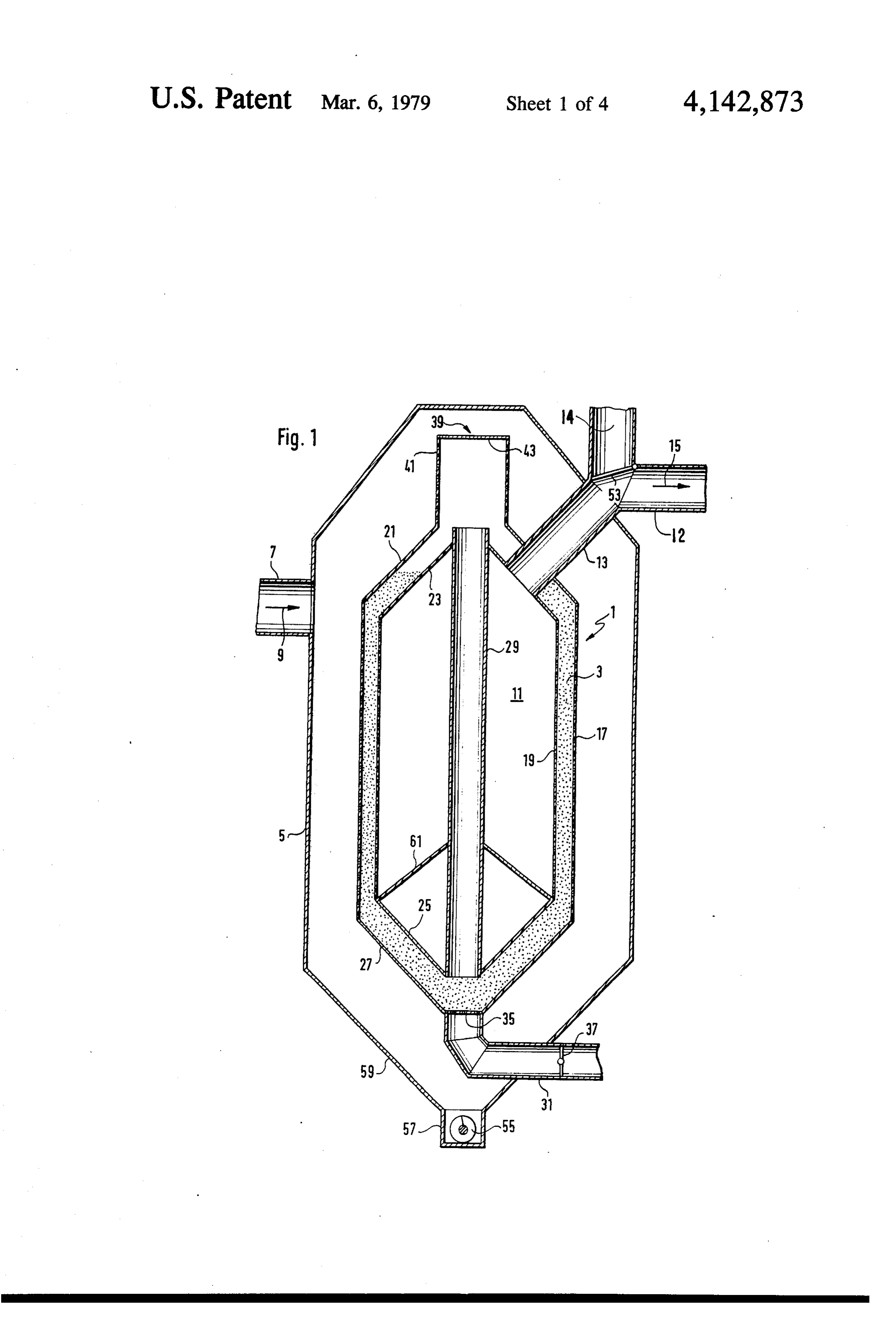
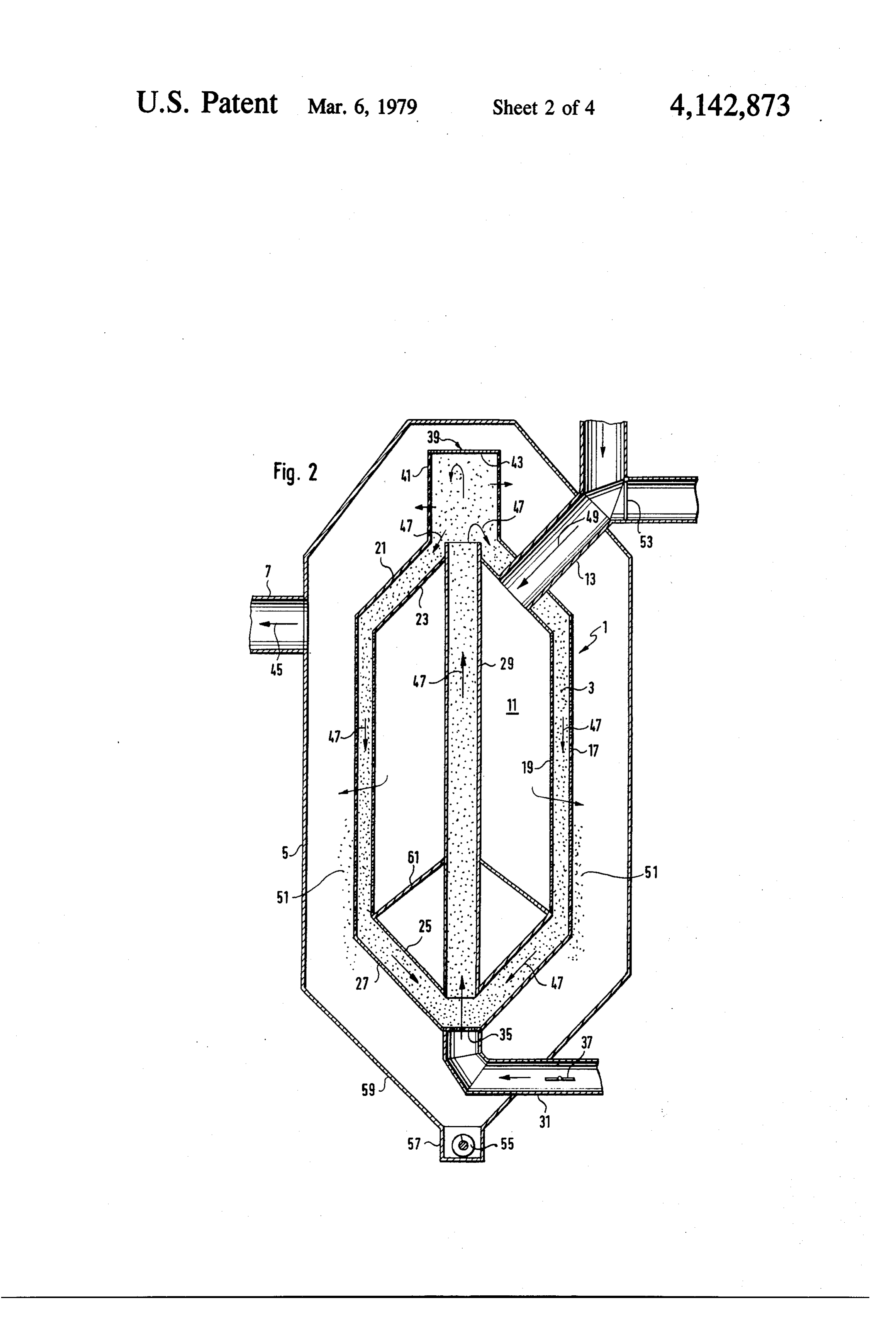
FIG. 1 shows a crude element. During the filtration phase the crude gas is element according to the invention gas filter incorporating a filter passed through the gas-permeable walls of the tubes phase, during the filtration into the interior of the filter element and the purified gas FIG. 2 shows the filter element of FIG. 1 during the led away through the duct leading out of the interior of the filter element. During the cleaning phase, scaveng 5 cleaning phase,
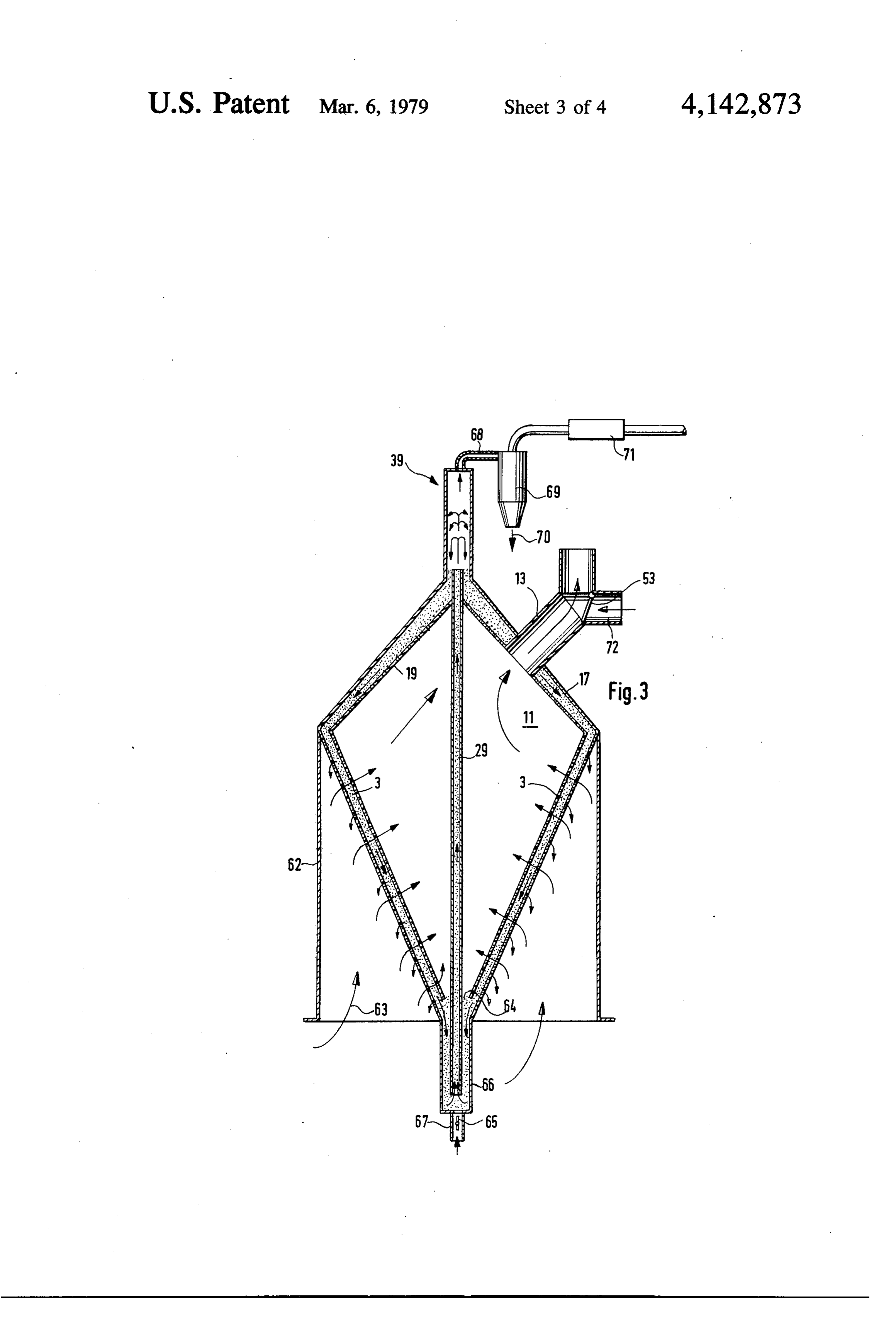
FIGS. 3-5 show further embodiments in section.
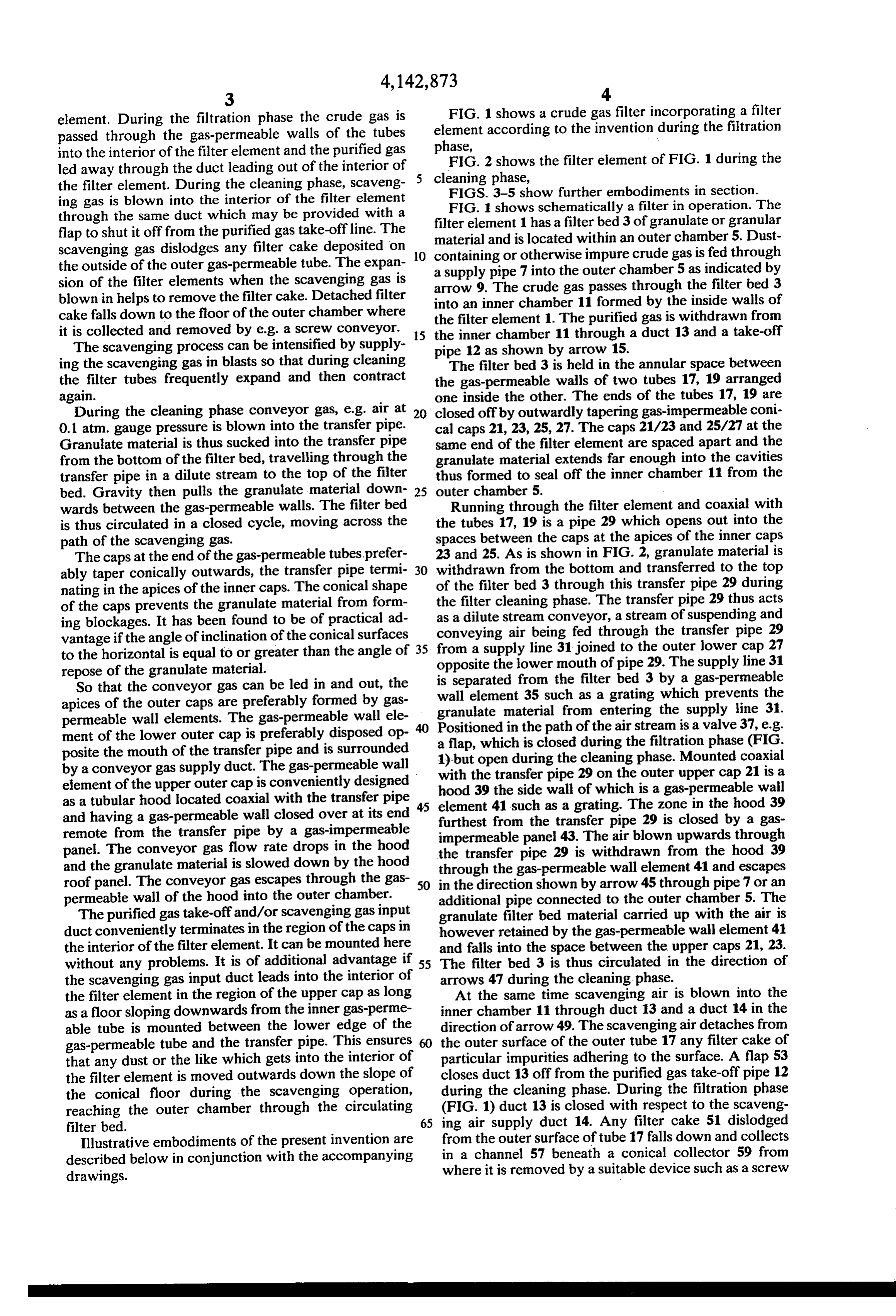
ing gas is blown into the interior of the filter element FIG. 1 shows schematically a filter in operation. The through the same duct which may be provided with a filter element 1 has a filter bed 3 of granulate or granular flap to shut it off from the purified gas take-offline. The material and is located within an outer chamber 5. Dust scavenging gas dislodges any filter cake deposited on 10 containing or otherwise impure crude gas is fed through the outside of the outer gas-permeable tube. The expan a supply pipe sion of the filter elements when the scavenging gas is arrow 9. The 7crude into the outer chamber 5 as indicated by gas passes through the filter bed 3 blown in helps to remove the filter cake. Detached filter into an inner chamber 11 formed by the inside walls of cake falls down to the floor of the outer chamber where the filter element 1. The purified gas is withdrawn from it is collected and removed by e.g. a screw conveyor. 5 the inner chamber 11 through a duct 13 and a take-off The scavenging process can be intensified by supply ing the scavenging gas in blasts so that during cleaning pipe 12 as shown by arrow 15. The filter bed 3 is held in the annular space between the filter tubes frequently expand and then contract the gas-permeable walls of two tubes 17, 19 arranged again. one inside the other. The ends of the tubes 17, 19 are During the cleaning phase conveyor gas, e.g. air at 20 closed off by outwardly tapering gas-impermeable coni 0.1 atm. gauge pressure is blown into the transfer pipe. cal caps 21, 23, 25, 27. The caps 21/23 and 25/27 at the Granulate material is thus sucked into the transfer pipe same end of the filter element are spaced apart and the from the bottom of the filter bed, travelling through the granulate material extends far enough into the cavities transfer pipe in a dilute stream to the top of the filter thus formed to seal off the inner chamber 11 from the bed. Gravity then pulls the granulate material down 25 outer chamber 5.
wards between the gas-permeable walls. The filter bed Running through the filter element and coaxial with is thus circulated in a closed cycle, moving across the the tubes 17, 19 is a pipe 29 which opens out into the path of the scavenging gas. spaces between the caps at the apices of the inner caps The caps at the end of the gas-permeable tubes prefer 23 and 25. As is shown in FIG. 2, granulate material is ably taper conically outwards, the transfer pipe termi 30 withdrawn from the bottom and transferred to the top nating in the apices of the inner caps. The conical shape of the filter bed 3 through this transfer pipe 29 during of the caps prevents the granulate material from form the filter cleaning phase. The transfer pipe 29 thus acts ing blockages. It has been found to be of practical ad as a dilute stream conveyor, a stream of suspending and vantage if the angle of inclination of the conical surfaces 35 conveying air being fed through the transfer pipe 29 from a supply line 31 joined to the outer lower cap 27 to the horizontal is equal to or greater than the angle of opposite the lower mouth of pipe 29. The supply line 31 repose of the granulate material.
So that the conveyor gas can be led in and out, the iswall separated from the filter bed 3 by a gas-permeable element 35 such as a grating which prevents the apices of the outer caps are preferably formed by gas granulate permeable wall elements. The gas-permeable wall ele Positioned material in the from entering the supply line 31.
path of the air stream is a valve 37, e.g.
ment of the lower outer cap is preferably disposed op posite the mouth of the transfer pipe and is surrounded a1)-but flap, which is closed during the filtration phase (FIG. open during the cleaning phase. Mounted coaxial by a conveyor gas supply duct. The gas-permeable wall with the transfer pipe 29 on the outer upper cap 21 is a element of the upper outer cap is conveniently designed hood 39 the side wall of which is a gas-permeable wall as a tubular hood located coaxial with the transfer pipe 45 element 41 such and having a gas-permeable wall closed over at its end furthest from theastransfer a grating. The zone in the hood 39 remote from the transfer pipe by a gas-impermeable impermeable panel 43. Thepipe 29 is closed by a gas air blown upwards through panel. The conveyor gas flow rate drops in the hood the transfer pipe 29 is withdrawn from the hood 39 and the granulate material is slowed down by the hood through the gas-permeable wall element 41 and escapes roof panel. The conveyor gas escapes through the gas 50 in the direction shown by arrow 45 through pipe 7 or an permeable wall of the hood into the outer chamber. additional pipe connected to the outer chamber 5. The The purified gas take-off and/or scavenging gas input granulate filter bed material carried up with the air is duct conveniently terminates in the region of the caps in however retained by the gas-permeable wall element 41 the interior of the filter element. It can be mounted here and falls into the space between the upper caps 21, 23. without any problems. It is of additional advantage if 55 The filter bed 3 is thus circulated in the direction of the scavenging gas input duct leads into the interior of arrows 47 during the cleaning phase.
the filter element in the region of the upper cap as long At the same time scavenging air is blown into the as a floor sloping downwards from the inner gas-perme inner chamber 11 through duct 13 and a duct 14 in the able tube is mounted between the lower edge of the direction of arrow 49. The scavenging air detaches from gas-permeable tube and the transfer pipe. This ensures 60 the outer surface of the outer tube 17 any filter cake of that any dust or the like which gets into the interior of particular impurities adhering to the surface. A flap 53 the filter element is moved outwards down the slope of closes duct 13 off from the purified gas take-off pipe 12 the conical floor during the scavenging operation, during the cleaning phase. During the filtration phase reaching the outer chamber through the circulating (FIG. 1) duct 13 is closed with respect to the scaveng filter bed. 65 ing air supply duct 14. Any filter cake 51 dislodged Illustrative embodiments of the present invention are from the outer surface of tube 17 falls down and collects in a channel 57 beneath a conical collector 59 from described below in conjunction with the accompanying drawings. where it is removed by a suitable device such as a screw
Page 8
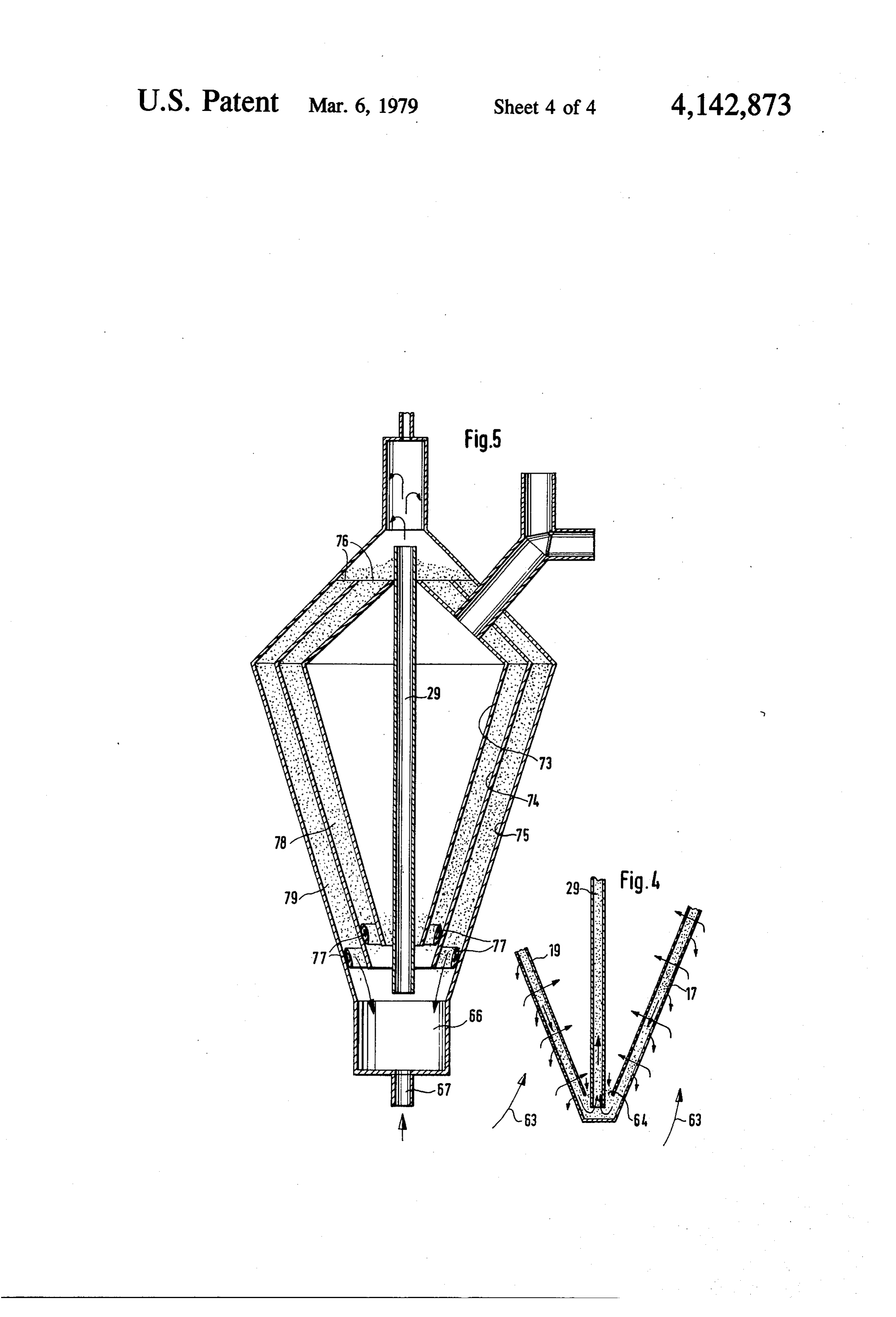
conveyor 55. Located between lower end of the inner A further embodiment of the filter of the invention is tube 19 and the transfer pipe 29 is a conical floor 61 shown in FIG. 3 in which parts already mentioned are sloping downwards from transfer pipe. 29. Any dust or denoted by the same reference numerals as in FIGS. 1 the like which has penetrated into the inner chamber 11 and 2. In this embodiment, too, the filter has an inner and collected on this floor is conveyed by the scaveng tube 19 and an outer tube 17. The transfer pipe 29 is ing air through the filter bed 3 into the outer chamber 5. again concentric with the two tubes 17 and 19 and ter Since during the cleaning phase air both circulates minates under a hood 39. Each of the two tubes is how and flows through the filter bed 3, cleaning times are ever made up of two cone-shaped sections with their particularly short. It is therefore possible to use granu bases placed together, a cylindrical or polygonal casing late material of very small grain size, e.g. 0.5 to 1 mm. 10 62 extending down from the circular joint between the Sand is the preferred granulate material. The width of two sections of the outer tube 17. The lower section of the filter bed 3 in the crude gas flow direction is very the inner tube 19 does not extend right down to the small, e.g. 10 to 15 mm. Transfer pipe 29 running transfer pipe 29, leaving a gap 64. The lower end of the through the inner chamber 11 reinforces the filter ele 15 transfer pipe 29 projects into a chamber 66 in which an ment 1 so that they can be replaced together as a single air supply line 67 with a valve 65 terminates. component. In this embodiment, the air stream circulates the filter The filter element 1 is preferably cylindrical. Its di bed by sucking the granulate material from between the ameter may be 10 cm to 1 m. The diameter and length tubes 17 and 19 through chamber 66 into the transfer of the tubes 17, 19 are chosen to suit the desired crude pipe 29 and carrying it up into the hood 39 where it falls gas throughput. FIGS. 1 and 2 show a filter with only 20 down between the tubes 17 and 19 again. The dustladen one filter element 1. If required, however, the outer conveyor air passes from the hood 39 through a duct 68 chamber 5 may contain several filter elements. The into a precipitator 69 where the already partly aggre transfer pipe 29 can also be made of electrically insulat gated dust particles are precipitated in the direction of ing material such as a plastic. The filter bed granules 25 arrow 70.
blown through the transfer pipe 29 during the cleaning Any dust particles still adhering to the granulate phase become electrically charged by frictional contact material fall inwards into the inner chamber 11 as the granulate material passes down between the upper sec with the transfer pipe 29, thus enhancing their ability to tions trap dust particles. When the granular material is quartz of tube 17 and 19, but is retained in the filter bed as the granulate passes down between the lower sections gravel, at least the inner surface of the pipe 29 is made 30 of of hard rubber. the tubes owing to the inwards-flowing crude gas. The dust which falls into the inner chamber 11 is sucked
During the cleaning phase, the scavenging air can be downwards passed into the inner chamber 11 in a continuous stream. through the gap 64, which is filled with The scavenging process can however be intensified by granulate material, and travels further with the granu supplying the scavenging air in blasts. The tubes 17, 19 35 lateThe material.
are preferably made of wire meshing and are shaken or device air 71 supply line 67 could be replaced by a suction positioned on the side of the dust precipitator set in vibration by the pulses of scavenging air so that 69 remote from the filter. Purified gas would be sucked any foreign bodies adhering to the outer surface of tube out of the inner chamber 11 through the gap 64 and into 17 are detached.
Supplying the scavenging air in blasts gives an addi 40 the transfer pipe 29, carrying the granulate material with it. The lower part of the filter could in this case be tional advantage however. Continuous operation can designed as shown in FIG. 4.
give rise to a situation in which the granulate material is In the embodiment of FIG. 3, therefore, the cleaning carried up through the transfer pipe 29 and deposited as a relatively loose bed between the two tubes 17 and 19. and filtration phases progress simultaneously, i.e. the granulate material is circulated continuously. The crude
Hence in normal operating conditions faults can occur, 45 gas flows in under the casing in the direction indicated particularly on starting up, since the gas to be filtered by arrow 63, passes through the filter bed 3 and finally favours the loosely packed areas of lower resistance. emerges from the filter as purified gas through duct 13. Not only does this lead to incomplete gas purification To enable the filter to be scavenged occasionally a but also to cavity formation and cave-ins in the filter scavenging air pipe 72 fitted with a shut-off device 53 bed. As is well known to those in the art, the filter bed 50 may be connected to duct 13. The scavenging air pipe material should in fact remain static during operation. 72 is not however necessary in small crude gas filters. The problem outlined above can however be com pletely overcome by supplying the scavenging air in down between the tubes 17 and 19material The cleaning of the granulate as it passes is of course further blasts. This causes the granulate material to vibrate and improved by decreasing the angle of the conical tubes, settle down snugly within the filter element. Even bet 55 i.e. by increasing the gravitational component acting on ter results are obtained if the blasts of scavenging air are the granules. The dust precipitator 69 is preferably a continued for a while, e.g. to 2 minutes, at the end of cyclone precipitator.
the cleaning phase after discontinuing the circulation of The degree of purification of the gas is even further the granular material. improved in the embodiment of FIG. 5. This embodi Although the caps 21/23 and 25/27 are gas-imperme 60 ment includes three tubes 73, 74, 75 similar in shape to able in the preferred embodiment of the invention, this the tubes 17, 19 in FIG. 3 and defining therebetween is not absolutely necessary. The lower caps 25/27 could annular chambers 78,79 having open upper ends 76 and be made of a gas-permeable material, particularly as the filled with granular filtering material. Located in the conical floor 61 seals off the inner chamber 11 from the lower conical sections of the chambers 78, 79 are shut outer chamber 5 at this end of the tubes 17, 19. If all or 65 off members 77 which enable either of the chambers 78 parts of the upper caps 21/23 are gas-permeable, care and 79 to be closed off or opened up as required. While must be taken that the granulate material fills the spaces the granulate material is passing down through chamber behind the gas-permeable parts. 78 into chamber 66, it can be stationary in chamber 79,
Page 9
thus ensuring that the crude gas is filtered thoroughly. (b) withdrawing the purified gas from said second After operating for a certain time like this, the proce wall during each filtration phase; dure is reversed so that chamber 78 is closed off and (c) withdrawing the granular material from said bot tom portion during each of a plurality of filter bed chamber 79 opened up. The shut-off members 77 may cleaning phases alternating with said filtration pha be inflatable annular tubes for instance. The perfora ses by suspending the granular material in a stream tions of the tubes 73,74, 75 and other features common of conveying gaseous material flowing toward a to the apparatus of FIG. 3 and FIG. 5 have been omit Zone above said top portion during each cleaning ted from FIG. 5. phase;
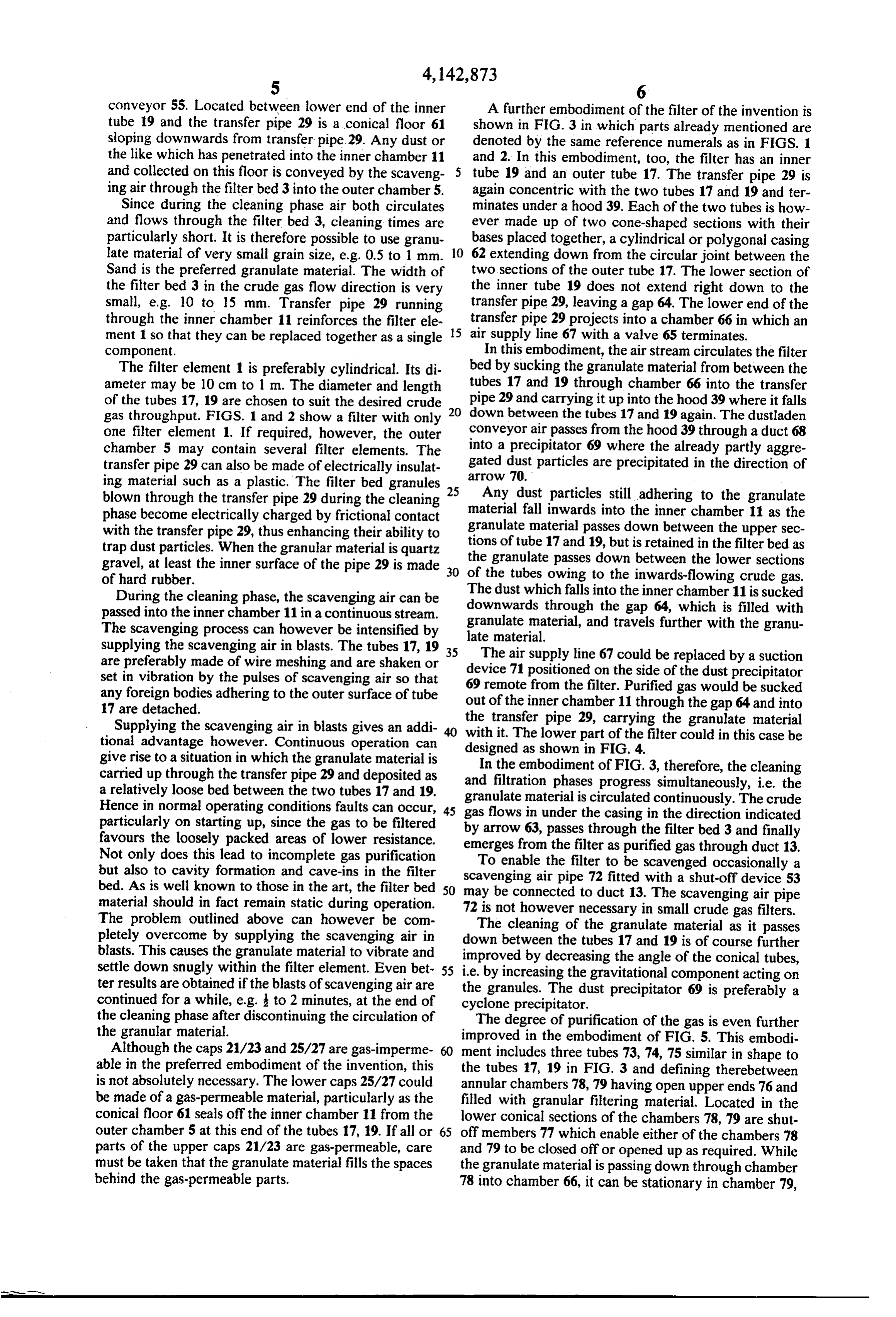
What is claimed is: 10 (d) separating the suspended granular material in said 1. A method of purifying a gas of solid suspended Zone from said stream during each cleaning phase; particles which comprises: (e) withdrawing said gaseous conveying material (a) passing the gas to be purified sequentially through from said zone separately from said granular mate a first vertically extending wall substantially per rial while permitting said granular material to meable to said particles, and through a filter bed of 15 move downward into said top portion during each granular material less permeable to said particles cleaning phase; and than said first wall and retaining said particles, (f) passing scavenging gas sequentially through said second wall, said filter bed, and said first wall dur whereby said gas is purified, and passing the puri ing each cleaning phase.
fied gas through a second, vertically extending 20 2. The method of claim 1, wherein said scavenging wall during each of a plurality of filtration phases, gas is passed through said walls and said filter bed in (1) said walls and said filter bed being permeable to sequential pulses.
said gas, and 3. The method of claim 1, wherein said granular ma (2) said granular material being confined in a space terial is being charged electrically while suspended in bounded by said walls, said space having top and 25 said stream. t t k sk bottom portions;
Provenance
- Collection
- Cited prior art
- Original PDF
- patentimages.storage.googleapis.com →
- Filed
- 1977-05-03
- Pages
- 9
- Method
- pdftotext (the PDF's own text layer) + pdftoppm 300dpi page scans
- Source
- Google Patents bibliographic record
- Granted
- 1979-03-06
- Inventors
- Wolfgang Berz; Gimag AG
- Transcribed from
- patentimages.storage.googleapis.com →