patent · US3439899
Method for the production and control of fluidized beds
22 April 1969
Page 1
Drawing sheet — no readable text.
Page 2
United States Patent Office 3,439,899 Patented Apr. 22, 1969
provements, for example by the use of baffles, gas dis 3,439,899 tribution perforated plates, mechanical vibration and
METHOD FOR THE PRODUCTION AND mixing devices, the use of mixed particle sizes, gas plus
CONTROL OF FE UDZED BEDS
Abe Hershler, Flushing, N.Y., assignor to Magneto Dy liquid flow schemes, special flow control valves, etc.; but these are far from satisfactory and leave much to be de namics, Inc., Bronx, N.Y., a corporation of New York 5 sired.
Int. CI. B01f 3/18, 11/00, 17/00 It is therefore a principal object of the present inven U.S. C. 259-1 17 Claims tion to provide an improved method for the handling and treatment of a solid particulate material.
0 Another object of the present invention is to provide
ABSTRACT OF THE DISCLOSURE an improved method for the production and maintenance A particulate material having distributed therethrough of a fluidized bed.
Small permanent magnets whose average individual size Still another object of the present invention is to pro is preferably between 2 and 10 times that of the non vide an improved method for producing and maintaining magnet particles is subjected to an upward flow of gas a fluidized bed which is stable, free of bubbles, slugs, and to a magnetic field varying with time direction and channeling, spouting or the like.
intensity to produce and control the resulting fluidized An additional object of the present invention is to pro bed. The varying magnetic field may be concentrated in vide an improved method for the surface control of fluid localized regions of the bed and surface control is 20 ized beds.
achieved by providing a horizontal varying magnetic field A further object of the present invention is to provide at the surface of the bed. Fluidization may be achieved an improved method for the production and maintenance without the gas flow and also without any non-magnet of a fluidized bed in the absence of any fluid flow for particles. effecting such fluidization.
-awaiiam Still a further object of the present invention is to A fluidized bed briefly consists of a mass of a particu provide an improved method for enhancing the fluid flow late solid material in which the individual particles are process of producing and maintaining a fluidized bed. in continuous motion relative to each other whereby the improved Another object of the present invention is to provide an mass or fluidized bed possesses the characteristics of a reliability,method of the above nature characterized by its adaptability, versatility and simplicity.
liquid. Like a liquid it will flow or pour freely, there is The above and other objects of the present invention a hydrostatic head pressure, it seeks a constant level, it will become apparent from a reading of the following de will permit the immersion of objects and will support rel scription, taken in conjunction with the accompanying atively buoyant objects, and in many other properties it drawings, wherein:
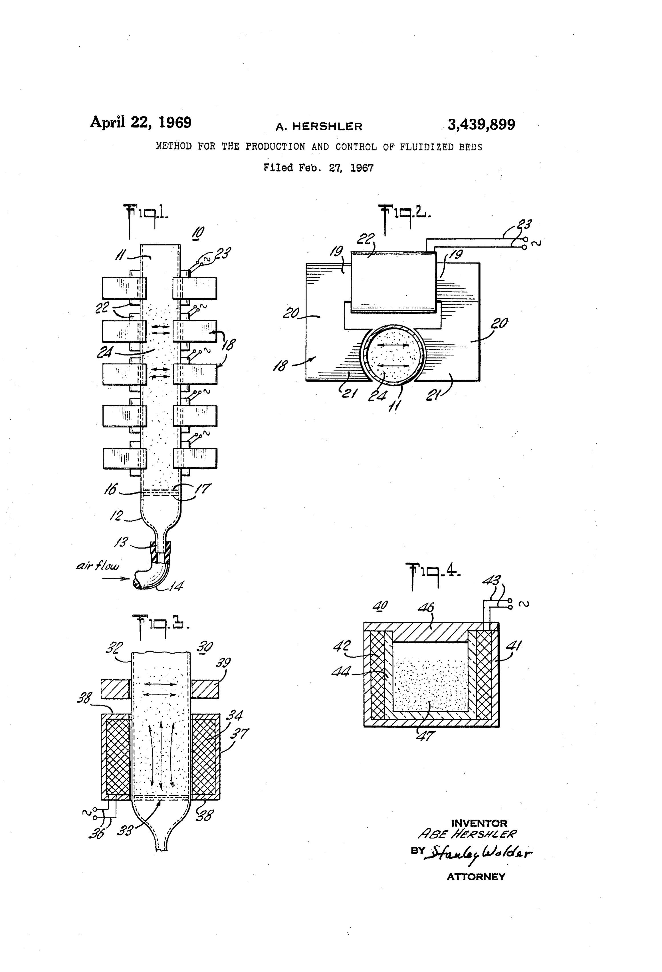
acts like a liquid. A fluidized bed is conventionally pro FIGURE 1 is a front elevational view of an apparatus duced by effecting a flow of a gas through a porous or 3 5 which may be employed to advantage in practicing the perforate plate or membrane underlying the particulate present method;
mass, at a sufficient rate to support the individual par FIGURE 2 is a top plan view thereof; ticles in a relatively continuously moving manner. A FIGURE 3 is a vertical sectional view of another minimum air flow or pressure drop is required to pro form of apparatus which may be employed; and duce fluidization and is known as the incipient fluidization 40 FIGURE 4 is a view similar to FIGURE 3 of still an and is dependent on many parameters including particle other form of apparatus.
size, particle density, etc. Any increase in the gas flow In a sense the present invention contemplates the pro beyond incipient fluidization causes an expansion of the vision of the method of producing a fluidized bed com fluidized bed to accommodate the increased gas flow until prising subjecting a mass normally in a non-fluidized con the gas velocity exceeds the free falling velocity of the dition and containing a particulate solid material includ particles which are then carried out of the apparatus. ing a plurality of separate discrete magnet particles hav Fluidized beds possess many applications, for example ing a coercive force exceeding 50 oersteds to a magnetic in temperature control, heat transfer, catalyst reactions, field varying with time in direction and intensity to im and various chemical and physical reactions such as oxida part individual motions to said magnet particles where tion, reduction, drying, polymerization, coating, diffusion, by to fluidize said particulate solid material. filtering and the like. However, the establishment and Advantageously the magnet elements are permanent maintenance of a stable fluidized bed by conventional pro magnets cedures is a sensitive and difficult process possessing many arbitrary of non-spherical and non-cylindrical, preferably shapes having an average particle size preferably drawbacks and disadvantages.
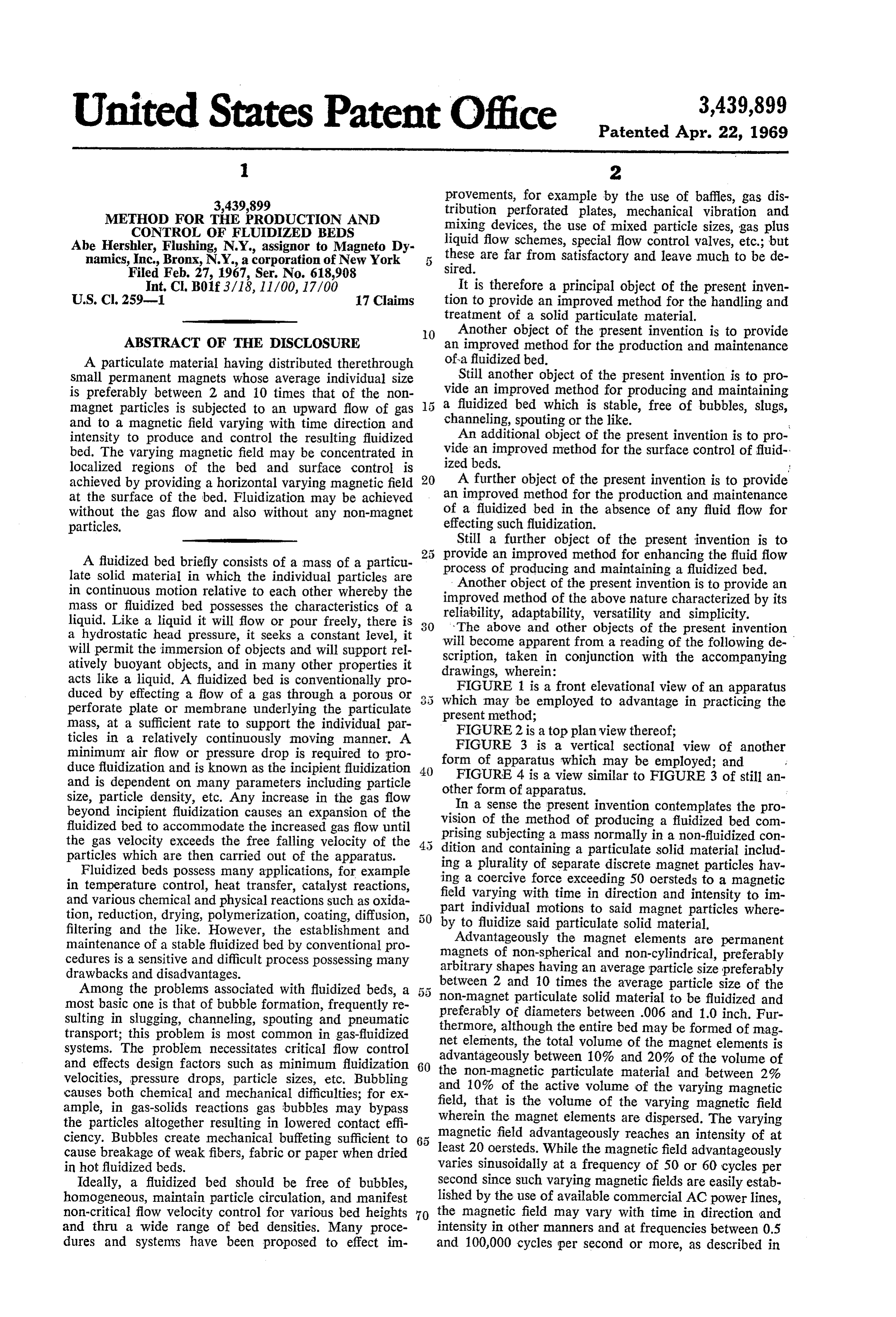
Among the problems associated with fluidized beds, a 55 between 2 and 10 times the average particle size of the most basic one is that of bubble formation, frequently re non-magnet preferably of particulate solid material to be fluidized and diameters between .006 and 1.0 inch. Fur sulting in slugging, channeling, spouting and pneumatic thermore, although the entire bed may be formed of mag transport; this problem is most common in gas-fluidized net elements, the total systems. The problem necessitates critical flow control advantageously betweenvolume 10% of the magnet elements is and 20% of the volume of and effects design factors such as minimum fluidization 60 velocities, pressure drops, particle sizes, etc. Bubbling the non-magnetic particulate material and between 2% and 10% of the active volume of the varying magnetic causes both chemical and mechanical difficulties; for ex ample, in gas-solids reactions gas bubbles may bypass field, that is the volume of the varying magnetic field wherein the magnet elements are dispersed. The varying the particles altogether resulting in lowered contact effi magnetic field advantageously reaches an intensity of at ciency. Bubbles create mechanical buffeting sufficient to cause breakage of weak fibers, fabric or paper when dried least 20 oersteds. While the magnetic field advantageously in hot fluidized beds. varies sinusoidally at a frequency of 50 or 60 cycles per Ideally, a fluidized bed should be free of bubbles, second since such varying magnetic fields are easily estab homogeneous, maintain particle circulation, and manifest lished by the use of available commercial AC power lines, non-critical flow velocity control for various bed heights 70 the magnetic field may vary with time in direction and and thru a wide range of bed densities. Many proce intensity in other manners and at frequencies between 0.5 dures and systems have been proposed to effect im and 100,000 cycles per second or more, as described in
Page 3
Hershler. Moreover, while fluidization of a particulate and each of the solenoids 22 consists of 500 turns of No. material may be effected in the substantial absence of an 26 copper wire. The porous plate 16 is a 200 mesh stain upward flow of fluid, it has been found that the use of an less steel screen and the screens 17 are 16 mesh. The re upward flow of fluid, advantageously a gaseous fluid, to 5 ceptacle 11 contained a mixture 24 of 45 milliliters of gether with the magnet elements and the varying magnetic 20–30 mesh clean Ottawa sand and 5 milliliters of rub field permits the production of fluidized beds in a man ber coated anisotropic barium ferrite permanent magnet ner which overcomes the many drawbacks encountered particles, approximately 42 cubic inch each in dimension by the use of the fluid flow alone. Among the advantages and of a coercive force of about 1200 oersteds. achieved by the use of the magnet elements and varying O Air was introduced into the pipe 14 at a pressure of magnetic field in augmenting the fluid flow are the elimina about 1 to 4 pounds per square inch and, in the absence tion or minimization of bubbling, channeling and slugging, of energization of the solenoids 22, the incipient fluidiza the lowering of the minimum required fluid flow rate, the tion velocity of the air through the mixture 24 was about reduction in the criticality of fluid flow control for opti 0.9 feet per second. Upon energization of the solenoids mum fluidized bed height, a radical improvement in the 22 at 60 cycles per second at a current of about 0.25 am fluid bed homogeniety, heat transfer and blending, the pere per solenoid, to produce a varying magnetic field of wide and simple control of bed heights and the very effec about 125 ampere turns per solenoid or about 70 oersteds tive control of the bed surface. per solenoid, the incipient fluidization air velocity fell to The permanent magnet elements or particles are pref about 0.5 feet per second.
erably dippled, ridged or otherwise shaped to prevent 20 The slugging air velocity in the absence of the vary intimate surface contact between the particles and may be ing magnetic field was about 1.4 feet per second. At uncoated or suitably coated with an organic polymeric this air velocity slugging was eliminated by energizing material, rubber, glass, silicone, inert metal plating, or the lower three solenoids 22 to produce a varying mag the like or may be encased in any desirable material in netic field at each yoke level of about 300 ampere turns cluding metals and ceramics. The minimum size of the or 150 oersteds with a power consumption of about permanent magnet element is that of a single magnetic 10 watts per solenoid. At an air velocity of about 3 feet domain (0.01 to several microns in diameter) and the per second through the receptacle, slugging and spout maximum size is between 0.5 and 5.0 centimeters in di ing were eliminated by energizing the lower three sole ameter. The coercive force of the magnet elements is ad noids 22 to produce a varying magnetic field at each vantageously as high as possible and should advantageous yoke level of about 500 ampere turns or 250 oersteds ly exceed 50 oersteds, Alnico 8 or barium ferrite (oriented with an individual solenoid power consumption of about and non-oriented) being highly satisfactory magnet mate 20 watts.
rials. The permanent magnet elements may be produced In the absence of the varying magnetic field, at in in any known manner, in powdered or crushed form or cipient fluidization, a 3% inch or 6% increase in bed cast or pressed to size and shape. 3 5 height was achieved. In the presence of the above vary The following examples are given merely by way of ing magnetic field of 70 oersteds per solenoid at incipient illustration and are not intended to limit the scope of the fluidization, a 5/8 inch or 8% increase in bed height present invention. occurred. It should be noted that increasing the ratio Referring now to the drawing, and particularly FIG of the number of magnet to non-magnet particles re URES 1 and 2 thereof which illustrate an apparatus which 40 Sults in increased control of the fluidized bed and as the may be advantageously employed in practicing the pres number of non-magnet particles approaches zero the ent invention, the reference numeral 10 generally desig fluid or gas velocity has very little effect on the fluidized nates the apparatus which includes an open topped ver bed.
tical cylindrical receptacle 11 formed of a non-magnetic The fluidized bed produced in the manner described material or one of low magnetic permeability. Such as above with the use of the varying magnetic field may glass, ceramic, plastic, non-magnetic metal or the like. The be employed for any of the application of conventional bottom 12 of the receptacle 11 is funneled to a vertical fluid beds with greater ease and versatility. The bed inlet pipe 13 which is connected by a tube 14 to a source density may be easily varied and adjusted and the con of compressed air. A horizontal porous plate 16 in... the figuration and homogeniety of the bed may be con form of a fine mesh screen extends transversely across trolled in many ways, for example by the use of mag the lower part of the receptacle 11 and is sandwiched be netic shims and magnetic focusing devices for the vary tween and supported by a pair of coarse screens 17. ing magnetic field. Moreover, the fluidized bed particulate A plurality of regularly vertically spaced similarly material may be magnetically confined since it has been shaped magnet yokes 18 preferably formed of laminated found that the particulate material is substantially re soft iron are positioned along the height of the receptacle 55 Strained against movement across the varying magnetic 11. Each yoke 18 is substantially U-shaped including a field lines in the presence of the magnet elements. Ex rear cross piece 19, and forwardly projecting side arms tremely effective bed surface control is one of the im 20 terminating in inwardly directed opposite legs 21 pro portant advantages. By energizing only the solenoid at vided with confronting cylindrical faces mating and sub the bed surface, surface control may even be critically stantially embracing the outer wall of the receptacle 11. 60 controlled and maintained despite internal bed slugging A solenoid or coil 22 is wound about each of the yoke at very high upward fluid velocities. cross pieces 19 and is connected by leads 23 to a source While in the arrangement described above, the varying of alternating current. Magnet particles, or a mixture 24 magnetic field is substantially horizontal it may be radial, of magnet and non-magnet particles satisfying the param inclined or vertical or assume any desired direction or eters above set forth are positioned in the receptacle 11 combination of directions. Thus, in the apparatus illus and may be fluidized by introducing air of at least the trated in FIGURE 3 a combination of horizontal and ver fluidization incipient velocity through the resulting fluid tical varying magnetic fields is employed. Specifically the ized bed or in accordance with the present invention, fluid apparatus 30 includes a receptacle 32 similar to the recep ization may be effected by sufficiently energizing one or tacle 11 described above and provided with a reinforced more of the solenoids 22 or by concurrently energizing porous plate assembly 33 along its bottom and connected one or more of the solenoids 22 and flowing air by way O at its bottom to a source of compressed air. The lower sec of the tube 14 upwardly through the receptacle 11. tion of the receptacle 32 is surrounded and engaged by a In accordance with a specific example of the operation vertical coaxial solenoid or coil 34 which is connected by of the apparatus 10, the receptacle 11 is a 1 inch diameter leads 36 to a source of alternating current whereby to pro glass tube 10 inches in length, Five /2 inch thick yokes 18 duce a time varying vertical magnetic field in the lower
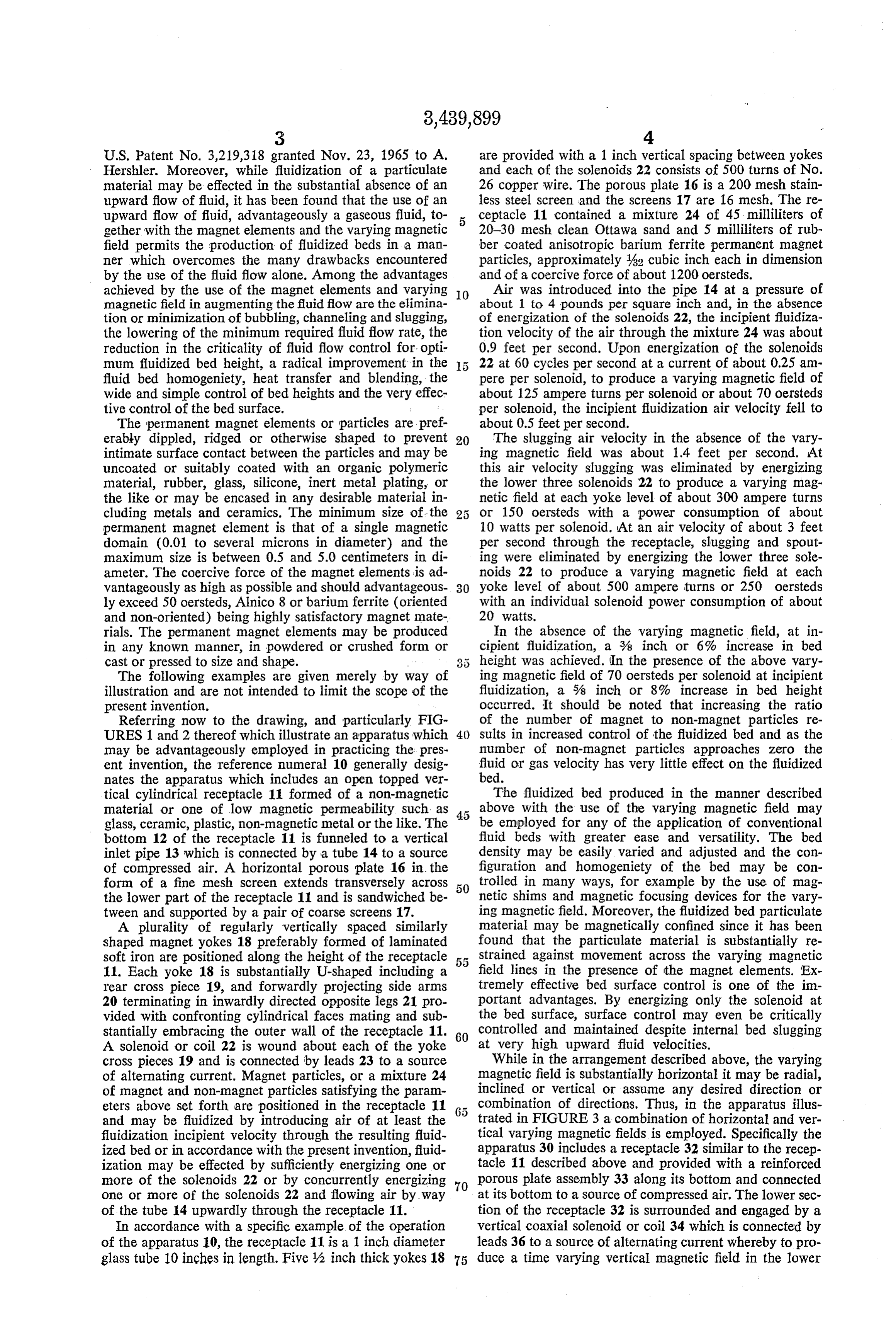
Page 4
part of the receptacle 32. The solenoid 34 is enclosed in a ments of the present invention it is apparent that numer cylindrical soft iron yoke 37 having annular end walls 38 ous alterations, additions and omissions may be made extending to the wall of the receptacle 32. without departing from the spirit thereof. For example, Positioned above the solenoid 34 are one or more ver while the fluidized bed has been illustrated in an overall tically spaced yokes 39 similar to the yokes 18 and pro 5 stationary state it may be advanced or mowed in any de vided with solenoids which are connected to alternating sired direction as by flowing through a chamber, pipe or current sources to produce time varying horizontal mag the like. Moreover, it should be noted that there are netic fields. The apparatus 30 is employed and operates in many conditions and parameters which contribute to the the manner of the apparatus 10 and is provided with an fluidization step, such as particle size both of the mag additional degree of control by reason of the vertical vary nets and the nonmagnet particles, relative sizes and quan ing magnetic field. As in the earlier described apparatus, 10 tities of these, gas flow, if any, frequency, configuration, the currents to the various solenoids may be individually shape and orientation of the varying magnetic field so controlled as may the air flow through the receptacle 32. that any precise dimensions of a suitable or optimum It should be noted that the horizontal and vertical varying varying magnetic field is not possible. However, the magnetic fields may be distributed in manners other than 15 optimum density of the varying magnetic field for a de those illustrated. Moreover, different motions may be im sired fluidized bed may be rapidly and easily determined parted to the magnetic field. For example, a rotating mag for netic field may be employed by providing two pairs of art inany set of ambient conditions by one skilled in the view of the above.
horizontal opposite yoke legs arranged in quadrature What is claimed is:
about the receptacle and energized by alternating currents 20 1. The method of producing a fluidized bed compris having a 90° phase difference. ing passing a fluid upwardly through a normally non-fluid In FIGURE 4 of the drawing there is illustrated an ap paratus 40 in which a fluidized bed may be produced in a ing amass ized containing a particulate solid material includ plurality of separate discrete magnet particles hav closed space in the absence of any upward fluid flow. The ing a coercive force exceeding 50 oersteds to impart an apparatus 40 includes an open topped cylindrical cup 25 upward force to the solid particles in said mass and sub shaped housing or shell 41 formed of a soft iron. Nested jecting said mass to a magnetic field varying with time in the housing 41 and coaxial therewith and extending for in direction and intensity to impart individual motions to the full length thereof is a solenoid 42 which is connected said magnet particles whereby to fluidize said particulate by leads 43 to an adjustable source of alternating current, solid material.
for example at 60 cycles per second. A glass, ceramic or 30 2. The method of claim 1 wherein said fluid is gaseous. other non-magnetic material cylindrical open topped re 3. The method of claim 1 wherein said varying mag ceptacle 44 nests in the solenoid 42. A suitable shaped lid netic field reaches an intensity exceeding 20 oersteds. 46 preferably of soft iron may be provided for closing the 4. The method of claim 1 wherein said magnet parti receptacle 44 and bridging the upper part of the yoke 41.
A solid particulate material 47 which is to be fluidized cles5. have a particle size between .006 and 1.0 inch. is located in the receptacle 44 and may be formed Solely Solid The method of claim 1 wherein said particulate material contains non-magnet particles and said of magnet elements or particles of the properties set forth magnet elements are permanent magnets and said fluid is above or a mixture thereof with non-magnet particles. In gaseous.
the absence of any upward fluid flow it has been found that the magnet elements should advantageously occupy at 40 cles6. have The method of claim 5 wherein said magnet parti a particle size between .006 and 1.0 inch and least 60% of the total volume of the particulate material. constitute between 10% and 20% of the volume of said As an example of the use of the apparatus 40 in accord non-magnet particles.
ance with the present invention the receptacle 41 was of 7. The method of claim 5 wherein the volume of said glass, 44 inches in diameter and 5% inches high, the magnet particles is between 2% and 10% of the active solenoid 42 was 1000 turns of #17 copper wire, and the volume of said varying magnetic field. housing 41 and lid 46 were 2 inch thick laminated silicon 8. The method of claim 1 wherein said magnet ele steel. The particulate material 47 consisted of 200 milli ments are permanent magnets.
meters of 64 inch cube shaped barium ferrite permanent 9. The method of claim 1 wherein said varying mag magnet particles.
When the apparatus 40 operated without the lid 46 and 50 netic 10.
field varies sinusoidally with time.
The method of claim 1 wherein said varying mag with the solenoid 42 unenergized the height of the partic netic field has a horizontal component through said par ulate material 47 was about 1 inch. Upon energization of ticulate material.
the solenoid at a power of 10 watts with a 220 volt, 60 11. The method of claim 10 wherein said horizontally cycle per second alternating current, the height of the ma terial or bed 47 was about 14 inch and in a churning 5 5 oriented varying magnetic field is restricted to the surface region of said particulate material.
motion. At a solenoid power consumption of 30 watts the 12. The method of claim 1 including controlling the fluidized bed 43 increased to a height of about 2 inches temperature of said particulate material while subject to and was in thorough agitation, and upon increase of the said varying magnetic field.
solenoid power to 100 watts the bed of material 47 rose to 13. The method of claim 1 wherein said varying mag 5 inches and resembled an advanced fluidized bed. With netic field has a vertical component through said par the solenoid power at 150 watts particle carryover oc 60 ticulate curred. material.
A constant temperature bath of 240 F. possessing ex 14. The method of claim 1 wherein said magnetic cellent properties was produced by immersing a tempera field is concentrated in a predetermined region of said ture controlled quartz heater into the bed and adjusting fluidized bed.
the solenoid power in the apparatus 40 to produce a fluid 65 15. The method of claim 1 wherein said particulate ized bed of about 2% inch height. The outside of the re Solid material consists substantially solely of separate ceptacle 44 was asbestos covered. The temperature re discrete magnetic particles.
sponse time of the fluidized bed was extremely rapid with 16. The method of effecting the motions of solid parti precise and excellent temperature control. It should be 70 cles in a fluidized bed of said particles in a gaseous am noted that non-magnet particles may be admixed with the bient environment comprising subjecting a plurality of magnet particles, but in the absence of any upward fluid separate discrete magnet particles having a coercive force flow these preferably should not exceed 40% of the total exceeding 50 oersteds and distributed throughout a region bed volume. of said fluidized bed to a magnetic field varying in direc While there have been described preferred embodi 75 tion and intensity with time.
Page 5
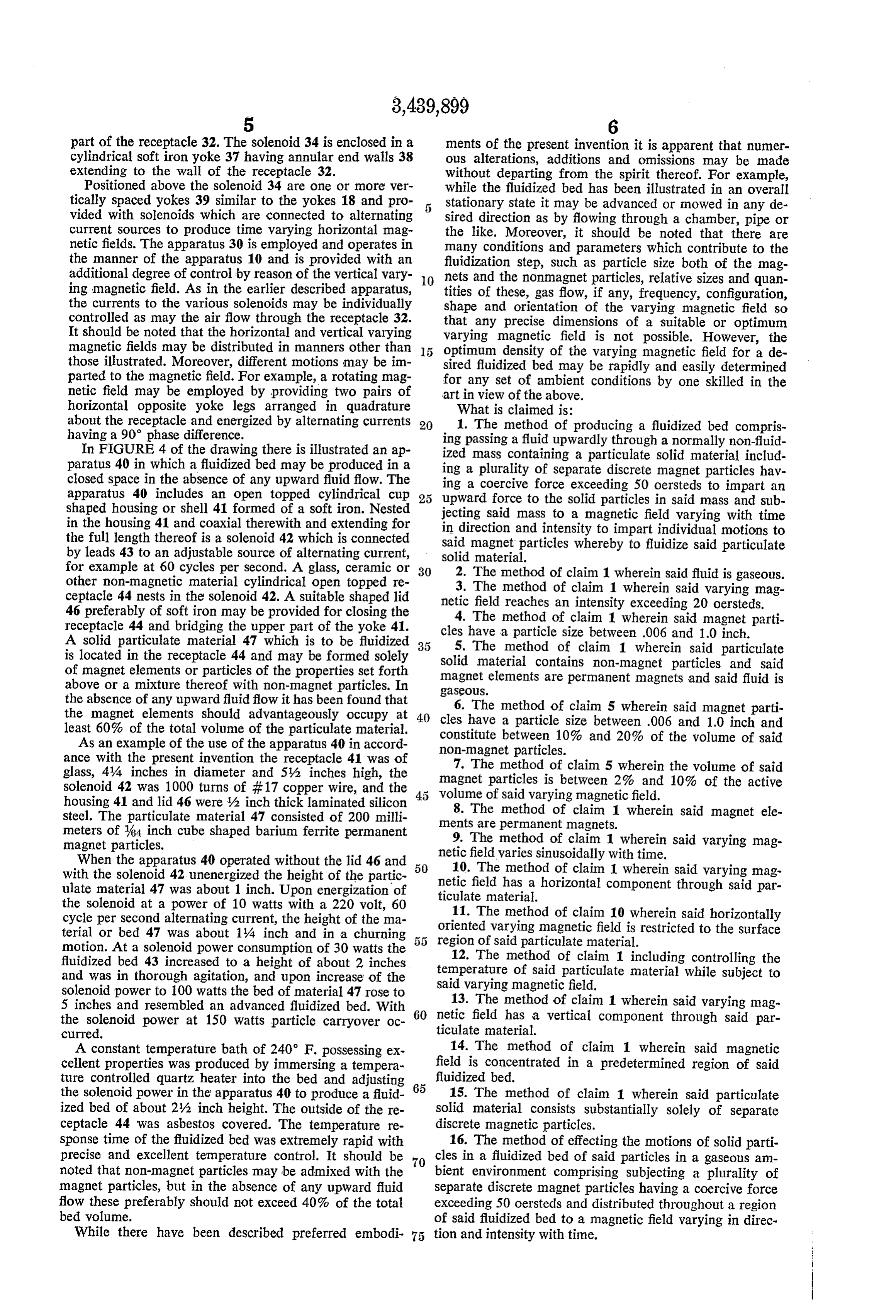
17. The method of producing a fluidized bed compris References Cited ing subjecting a normally non-fluidized mass containing UNITED STATES PATENTS a particulate solid material in a gaseous ambient environ 2,852,586 9/1958 Steele ------------ 259-99 X ment including a plurality of separate discrete magnet 3,219,318 11/1965 Hershler ------------- 259-1 particles having a coercive force exceeding 50 oersteds 3,246,373 4/1966 Lyman ----------- 259-99 X to a magnetic field varying with time in direction and in 3,314,670 4/1967 Kennedy ------------- 259-1 tensity to impart individual motions to said magnet parti cles whereby to fluidize said particulate solid material. ROBERT W. JENKINS, Primary Examiner.

Provenance
- Collection
- Cited prior art
- Original PDF
- patentimages.storage.googleapis.com →
- Filed
- 1967-02-27
- Pages
- 5
- Method
- pdftotext (the PDF's own text layer) + pdftoppm 300dpi page scans
- Source
- Google Patents bibliographic record
- Granted
- 1969-04-22
- Inventors
- Abe Hershler; Magneto Dynamics Inc
- Transcribed from
- patentimages.storage.googleapis.com →