patent · US4433633
Controlled gas generator system
28 February 1984
Page 1 — bibliographic record
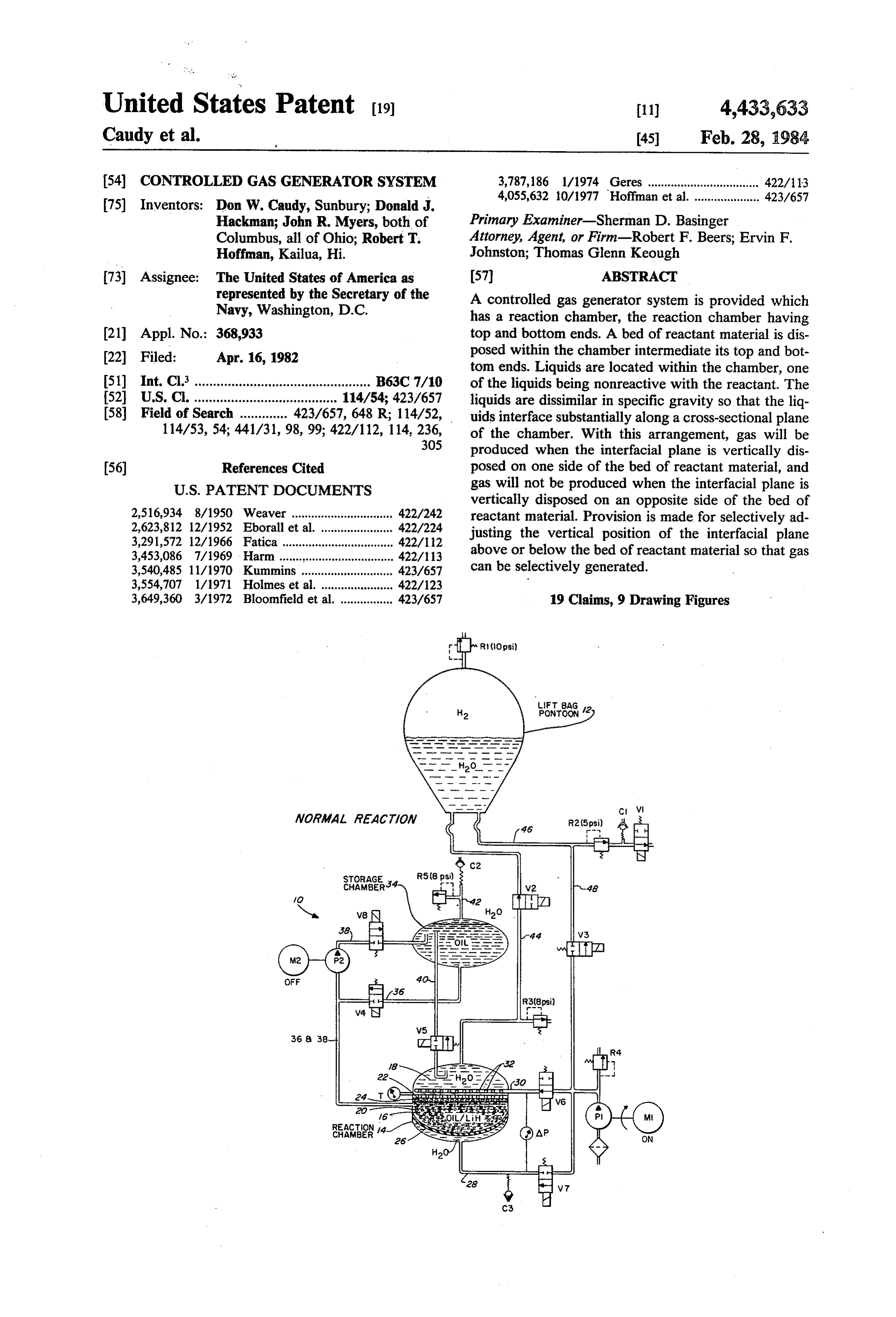
United States Patent (19) 11 4,433,633 Caudy et al. 45 Feb. 28, 1984 54 CONTROLLED GAS GENERATOR SYSTEM 3,787,186 1/1974 Geres .................................. 422/13 4,055,632 10/1977 Hoffman et al. .................... 423/657 (75) Inventors: Don W. Caudy, Sunbury; Donald J.
Hackman; John R. Myers, both of Primary Examiner-Sherman D. Basinger
Columbus, all of Ohio; Robert T. Attorney, Agent, or Firm-Robert F. Beers; Ervin F. Hoffman, Kailua, Hi. Johnston; Thomas Glenn Keough (73) Assignee: The United States of America as 57 ABSTRACT represented by the Secretary of the A controlled gas generator system is provided which Navy, Washington, D.C. has a reaction chamber, the reaction chamber having 21 Appl. No.: 368,933 top and bottom ends. A bed of reactant material is dis (22 Filed: Apr. 16, 1982 posed within the chamber intermediate its top and bot tom ends. Liquids are located within the chamber, one 51) Int. Cl. ................................................ B63C 7/10 of the liquids being nonreactive with the reactant. The 52 U.S. C. ....................................... 114/54; 423/657 liquids are dissimilar in specific gravity so that the liq 58 Field of Search ............. 423/657, 648 R; 114/52, uids interface substantially along a cross-sectional plane 114/53, 54; 44.1/31, 98, 99; 422/112, 114, 236, of the chamber. With this arrangement, gas will be 305 produced when the interfacial plane is vertically dis (56) References Cited posed on one side of the bed of reactant material, and
vertically disposed on an opposite side of the bed of 2,516,934 8/1950 Weaver ............................... 422/242 reactant material. Provision is made for selectively ad 2,623,812 12/1952 Eborall et al. ...................... 422/224 justing the vertical position of the interfacial plane 3,291,572 12/1966 Fatica ........... ... 422/112 3,453,086 7/1969 Harm ... ... 422/13 above or below the bed of reactant material so that gas 3,540,485 11/1970 Kummins ..... ... 42.3/657 can be selectively generated.
3,649,360 3/1972 Bloomfield et al. ................ 423/657 19 Claims, 9 Drawing Figures
fka Ri (opsi)
Ft. BAG
WOAMAA. AEAO/OW
STORAGE
REACTION,
SEES 14
Page 2
Drawing sheet — no readable text.
Page 3
Drawing sheet — no readable text.
Page 4
Drawing sheet — no readable text.
Page 5
Drawing sheet — no readable text.
Page 6
Drawing sheet — no readable text.
Page 7
Drawing sheet — no readable text.
Page 8
Drawing sheet — no readable text.
Page 9
Drawing sheet — no readable text.
Page 10
ing detailed description when considered in connection
CONTROLLED GAS GENERATOR SYSTEM with the accompanying drawings.
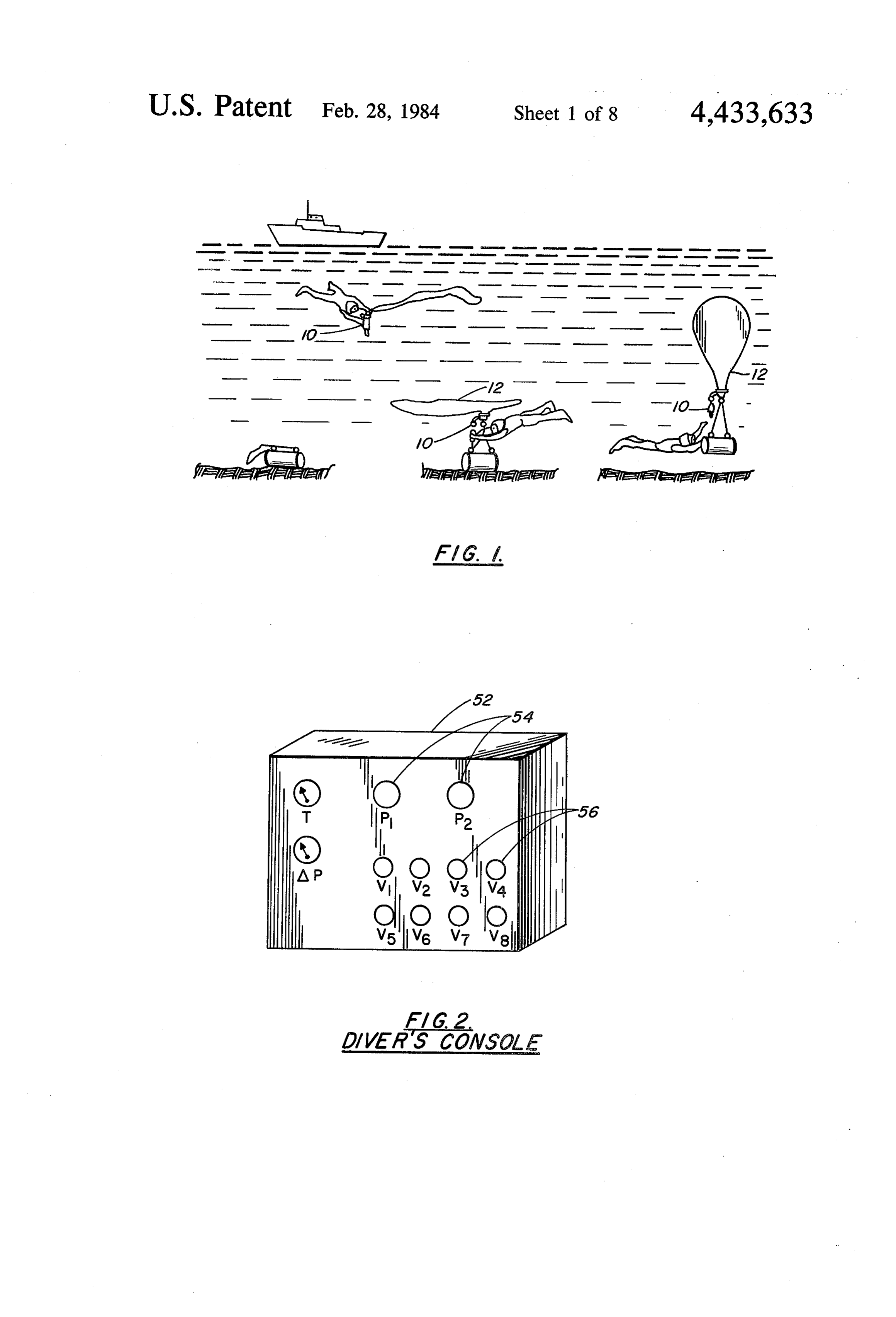
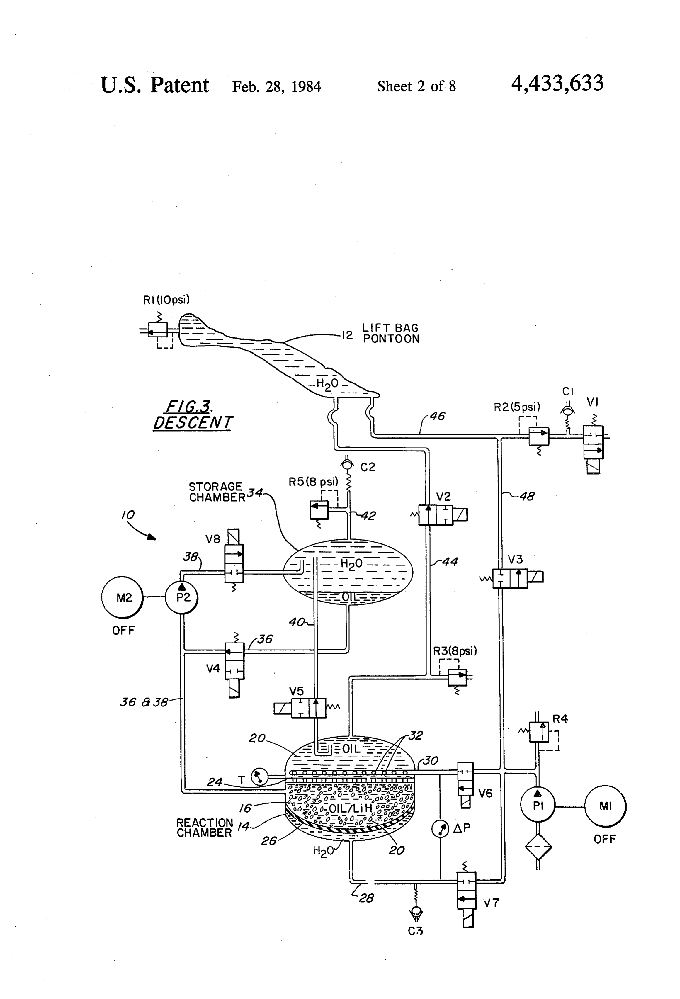
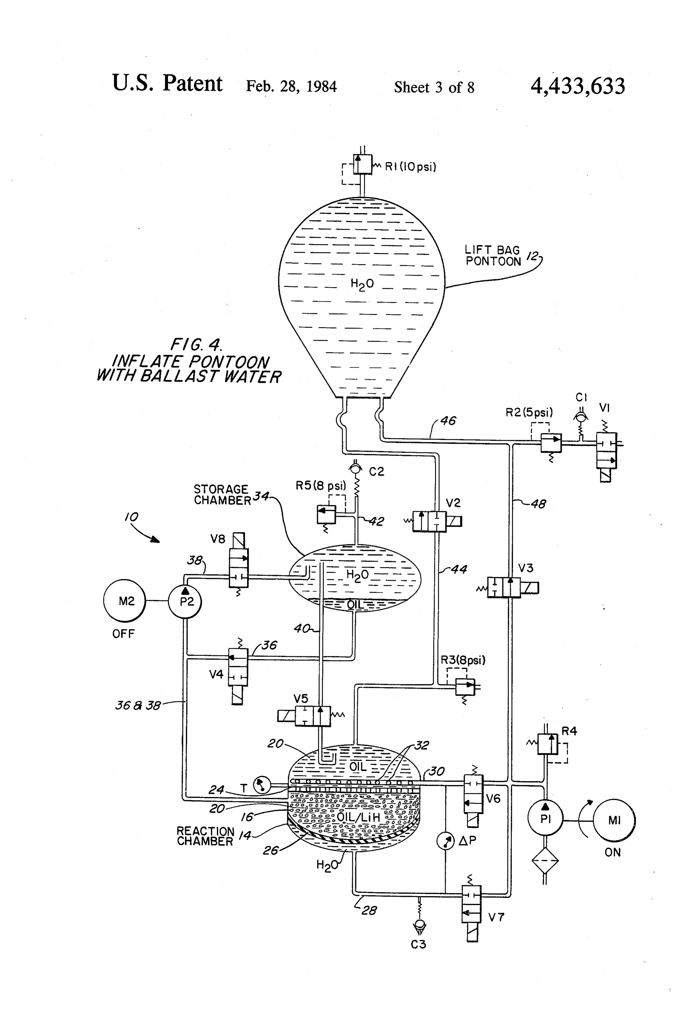
STATEMENT OF GOVERNMENT INTEREST BRIEF DESCRIPTION OF THE DRAWINGS The invention described herein may be manufactured 5 FIG. 1 is an ocean elevation view illustrating an ex and used by or for the Government of the United States emplary use of the present invention for salvaging an of America for governmental purposes without the object from the bottom of the ocean. payment of any royalties thereon or therefor. FIG. 2 is an isometric view of an exemplary console
BACKGROUND OF THE INVENTION
which can be utilized by a diver to control the present 10 invention.
Variable buoyancy systems are commonly employed FIGS. 3 through 9 are schematic illustrations of the in salvaging objects from the ocean or positioning and controlled gas generator system used with a lift bag recovering oceanographic instrumentation. These pontoon with valves and pumps shown in different buoyancy systems may take several different forms, modes to accomplish the various desired salvaging op such as lift bags or ballast tanks. Historically, high-pres erations.
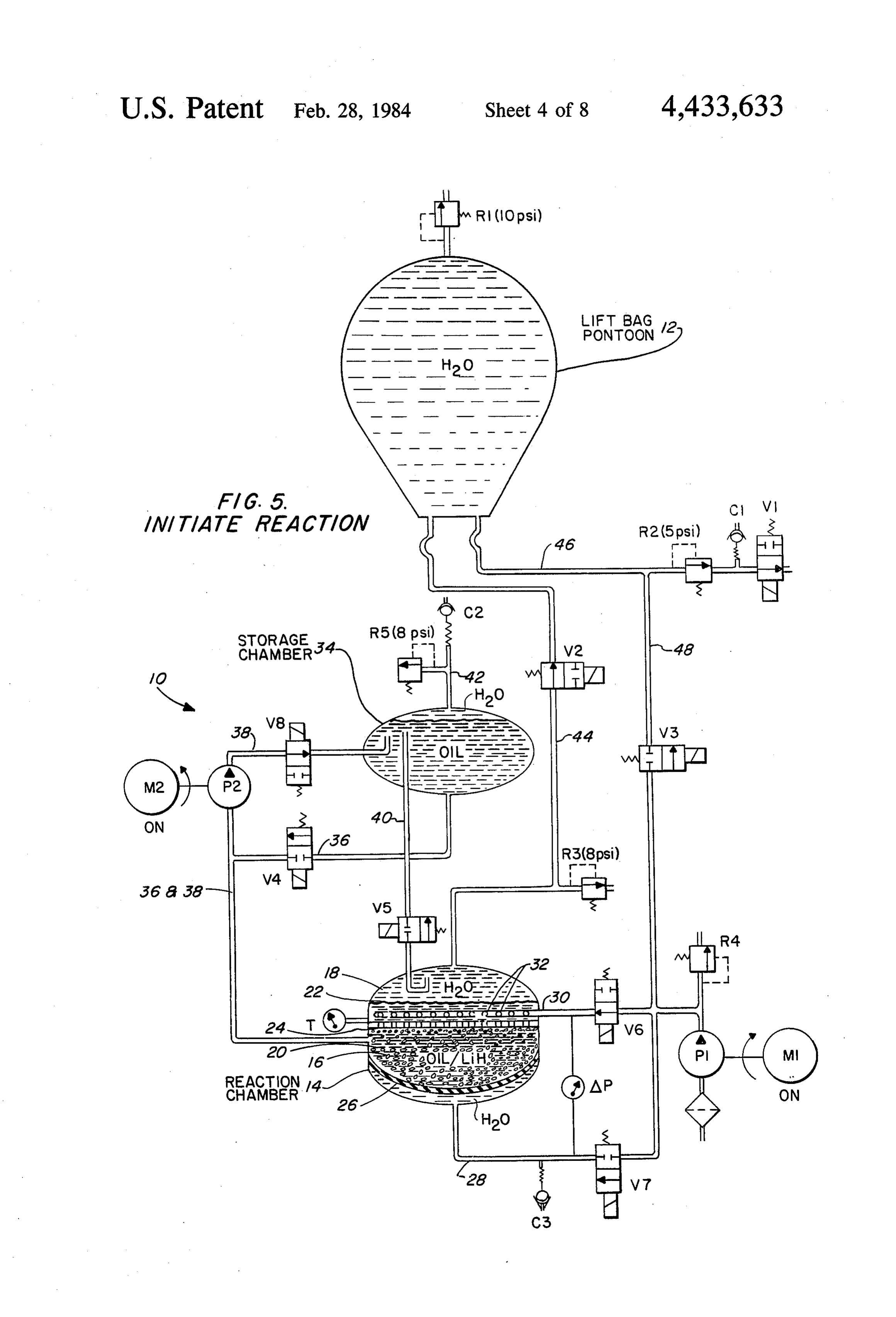
sure air tanks have been utilized for deballasting such DESCRIPTION OF THE PREFERRED buoyancy systems. More recently, various materials EMBOOMENT have been reacted to generate a gas for deballasting the systems. Hydrazine is commonly reacted to generate a Referring now to the drawings wherein like refer gas, and has been found highly satisfactory for raising 20 ence numerals designate like or similar parts throughout objects from the ocean bottom. However, hydrazine is the several views there is illustrated in FIG. 1 a practi not cost effective and is very hazardous for personnel to cal utilization of the present invention for recovering an handle. object from the ocean bottom. In this figure a diver is Gas generated by reacting metallic hydrides is safer 25 shown utilizing the controlled gas generator system 10 and considerably more cost effective than hydrazine. in combination with a lift bag pontoon 12. However, prior art metallic hydride gas generators The elements for the controlled gas generation sys could not be sufficiently controlled to perform their tem 10 and the lift bag pontoon 12 are identical in FIGS. intended job functions. The specific problem associated 3 through 9, the only difference being in the modes of with such prior art gas generators is in the starting and the various valves, motors, and lift bag to accomplish stopping of the reaction.In U.S. Pat. No. 4,055,632 to 30 the various salvage functions. Accordingly, description Robert T. Hoffman there is shown a controllable gas generator which utilizes metallic hydride pellets which of the elements of the invention will simply be accom plished by reference to FIG. 5. As illustrated in FIG. 5, are selectively released from a nonreactive liquid to a the gas generator reactive liquid for the generation of gas. This generator 14 which has topsystem 10 includes a reaction chamber and bottom ends. A bed of reactant is satisfactory for raising small objects, however, a more 35 material 16 is disposed within the reaction chamber practical system is required for raising large objects from the ocean bottom. Also, the gas generator de intermediate its top and bottom ends.
scribed in the patent will not terminate the generation of Liquids 18 and 20 are located within the chamber, gas quickly since the pellets must be completely ex one of the liquids 18 being reactive with the reactant 16 pended once they are disseminated into the reactive 40 and the other liquid 20 being nonreactive therewith. liquid. The liquids have dissimilar specific gravities so that they will interface substantially along a cross-sectional
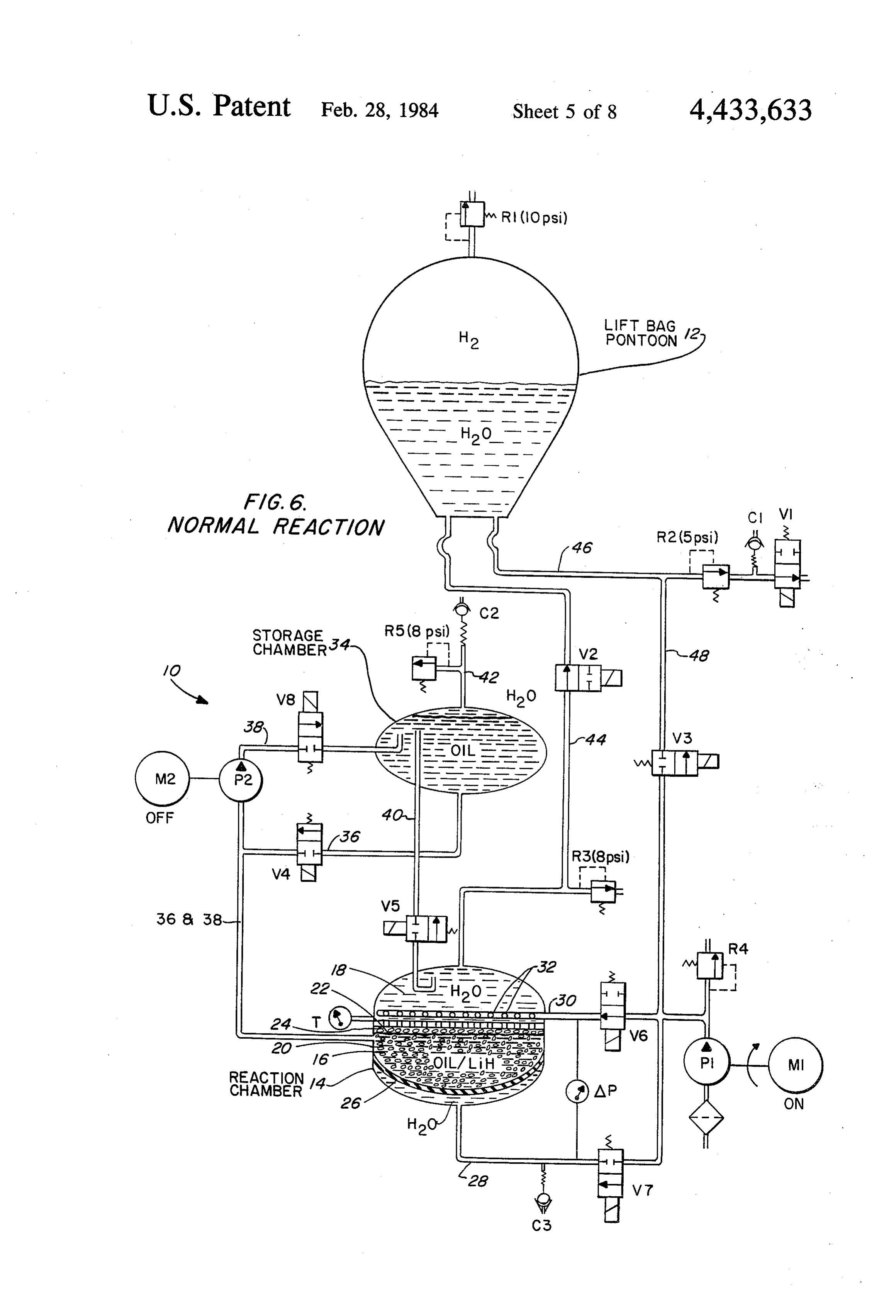
STATEMENT OF THE OBJECTS OF THE plane 22 of the chamber. With this arrangement, gas INVENTION will be produced when the interfacial plane is vertically An object of the present invention is to overcome the 45 disposed on one side of the bed of reactant material 16 aforementioned problems associated with prior art gas and gas is not produced when the interfacial plane is generators. vertically disposed on an opposite side of the bed of Another object is to provide a gas generator which reactant material, the latter condition being illustrated can be easily controlled to start and stop a gas produc in FIG. 5. Means, which will be described in detail ing reaction. hereinafter, are provided for selectively adjusting the A further object is to provide a gas generator in vertical position of the interfacial plane 22 above or which the starting and stopping of a reaction involving below the bed of reactant material 16 so that gas can be a metallic hydride can be substantially instantaneously selectively generated. In FIG. 6 the interfacial plane 22 started or stopped. is shown below the bed of reactant material in which Still another object is to provide a controlled gas 55 case gas is generated.
generator of the type utilizing a reactant, a nonreactive As illustrated in FIG. 5, the nonreactive liquid 20 liquid, and a reactive liquid in which the reaction be may have a higher specific gravity than the reactive tween the reactant and the reactive liquid can be liquid 18. The reactant material 16 is shown as being in stopped without requiring any pumping operation. nodule form and has a specific gravity which is less than Still a further object is to provide a gas generator of 60 the specific gravity of the nonreactive liquid 20 so that the type utilizing a nonreactive liquid in which the the nodules will float therein. A perforated member or motint of nonreactive liquid can be kept to a minimum. plate 24, which may simply be a screen, is mounted Yet another object is to provide a method of generat traversely across the entire reaction chamber 14 so as to ing gas which will efficiently control the starting and provide a top containment of the reactant material. The stopping of a reaction of gas producing materials. 65 perforated member 24 has perforations which are Other objects and many of the attendant advantages smaller in size than the nodular size of the reactant of this invention will be readily appreciated as the same material 16. As shown in FIG. 5 the reactant material 16 becomes better understood by reference to the follow and the nonreactive liquid 20 are both located below the
Page 11
screen 24 which causes the reactant material to be to the reaction chamber 14. A normally open solenoid buoyed up against the bottom of the perforated member valve V4 is interconnected in the first nonreactive liq 24. uid line 36 for controlling the dissemination of nonreac In the preferred embodiment, the reactant material 16 tive liquid by gravity flow. A second nonreactive liquid is lithium hydride, the reactive liquid 18 is water, and line 38 interconnects the reaction chamber 14 at a posi the nonreactive liquid 20 is fluorocarbon oil such as tion below the perforated member 24 to the storage "Halocarbon' oil 13-21, which is the trademark for an chanber 34. A pump P2 and a normally closed solenoid oil obtainable from Halocarbon Products Corporation. V8 are interconnected in the second nonreactive liquid The reactant material may be formed into cubes by line 38 for controlling the transfer of the nonreactive using a combination of 10% Teflon and 90% lithium 10 liquid from the chamber 14 to the storage chamber 34. hydride powders compressed under high pressures in The selective adjusting means may still further in the order of 60,000 pounds per square inch. The cubes clude a second reactive liquid line 40 which intercon may be one inch and the perforated member may be 10 nects the reaction chamber 14 above the perforated mesh screen so that the cubes are retained below the member 24 to the storage chamber 34. A normally open screen. The density of these lithium hydride cubes is 15 solenoid valve. V5 may be interconnected in the second approximately 0.8 and the density of the "Halocarbon' reactive liquid line 40 for controlling transfer of the oil is approximately 1.9. reactive liquid from the chamber 14 to the storage The nonreactive fluorocarbon oil 20 is somewhat chamber 34 as the reactive liquid is displaced by the expensive, and a unique feature has been employed for incoming nonreactive liquid in the reaction chamber 14. using a minimum amount of this oil in the system. This 20 A third reactive liquid line 42 may be connected into has been, accomplished by providing a resilient dia the top of the storage chamber 34 and may have a por phragm 26 which is mounted transversely across the tion which extends outwardly therefrom. An intake entire reaction chamber between the screen 24 and the check valve C2 and a relief valve R5 may be intercon chamber bottom. The space below the diaphragm 26 is nected in parallel in the outwardly extending portion of adapted to contain water, the volume of which can be 25 the third reactive liquid line 42 for intaking or discharg selectively increased or decreased. A water line 28 is ing reactive liquid as needed.
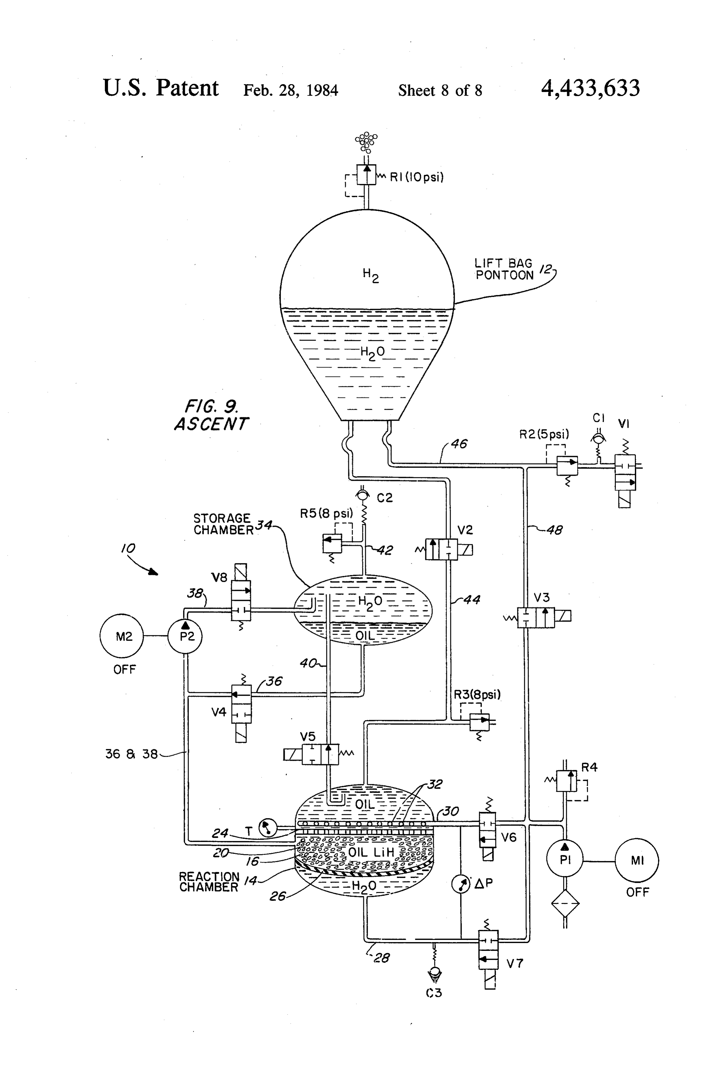
connected into the bottom of the reaction chamber for The foregoing describes a complete controlled gas introducing water on the bottom side of the diaphragm generation system. This system may be utilized for the 26, the water line 28 being connected to a pump P1. purpose of inflating the lift bag pontoon 12 with gas, Interconnected in the water line 28 are a normally 30 such as hydrogen. The lift bag 12 has a top and a bottom closed valve V7 and an intake check valve C3, Valve when inflated, as illustrated in FIG.5. A relief valve R1 V7, as well as the other 'V' numbered valves described is connected into the top of the lift bag for venting herein, may be of the solenoid type wherein energiza expanding gas during ascent. The operation of this lift tion causes repositioning to a position opposite its nor bag can be more fully appreciated by referring to U.S. mal position. When valve V7 is energized to the open Pat. No. 4,078,509 entitled "Salvage Apparatus and position and pump P1 is operated water will be fed to Method'.
the bottom of the reaction chamber 14 causing the dia In order to inflate the lift bag 12 a gas line 44 inter phragm 26 to move upwardly to lessen the volumetric connects the top of the reaction chamber 14 with the lift space between the diaphragm 26 and the screen 24. This bag 12. The gas line 44 is also capable of carrying reac operation will be utilized as the lithium hydride cubes tive liquid to the lift bag 12, which in the preferred 16 are used up in the reaction process. The result is a embodiment, would be water. A normally open sole savings in the overall amount of fluorocarbon oil 20 noid valve V2 is interconnected in the line 44 for con which will be required to construct an operational em trol purposes. Optionally, a relief valve R3 may be bodiment of the invention. connected in the line 44 for preventing overpressure. A The means for selectively adjusting the vertical posi 45 discharge reactive liquid line 46 is connected to the tion of the interfacial plane 22 of the liquids above or bottom of the lift bag 12 and has an outer ambient end below the bed of reactant material may include a first portion. A normally closed solenoid valve V1 is inter reactive liquid line 30 which has a portion which ex connected in the line 46, and a relief valve R2 is inter tends transversely into the reaction chamber 14 in a connected in the line 46 between the valve V1 and the spaced relationship above the perforated member or 50 bottom of the lift bag 12. With this arrangement, reac screen 24 and which has an outer end which is connect tive liquid, which is water in the preferred embodiment, able to a pump, such as pump P1. In the preferred em can be discharged from the lift bag 12 when a predeter bodiment the inner portion of the liquid line 30 has a mined overpressure is present. An intake check valve plurality of openings 32 distributed in an equally spaced C1 may be interconnected in the line 46 between the relationship along its length. Control of the dissemina 55 valve V1 and the relief valve R2 for the purpose of tion of reactive liquid into the chamber 14 may be ac relieving increasing ambient pressure between these complished by a normally closed solenoid valve V6 two valves. An intake reactive liquid line 48, which which is interconnected in the line 30 outside the cham would be a water line in the preferred embodiment, is ber 14. interconnected between the pressure side of the pump The selective adjusting means may further include a 60 P1 and the lift bag 12. A normally closed solenoid valve nonreactive liquid storage chamber 34 which is dis V3 may be interconnected in the line 48 for control posed above the reaction chamber 14. Any suitable purposes and a relief valve R4 may be provided for means may be utilized for maintaining this positional relieving overpressures. The line 48 and the valve V3 is relationship, such as a framework (not shown). A first not absolutely necessary since the lift bag 12 could be nonreactive liquid line 36 interconnects the reaction 65 filled by the use of the line 30 provided proper control chamber 14 below the screen 24 to the nonreactive is maintained on the valve V6. liquid storage chamber 34 for allowing nonreactive As can be seen in FIG. 5 motors M1 and M2 may be liquid to flow by gravity from the storage chamber 34 utilized for operating pumps P1 and P2, respectively. In
Page 12
the preferred embodiment, the relief valves are set at TABLE 1-continued particular levels, namely: R1 is set at 10psi, R2 is set at ITEM '. FUNCTIONS 5 psi, R3 is set at 8 psi, and R5 is set at 8 psi. Power for the gas generation system may be provided by a battery Equalization reaction chamber 14 to the storage (not shown) which is electrically connected to the mo Valve (N. O.) chamber 34. It is open when V4 tors and all of the solenoid valves. Between the lines 28 s is open and closed when V4 is closed.
and 30 there may be provided a pressure gage AP for v6 Reaction Water Used to admit water to the indicating the differential pressure between these two Valve (N, C.) reaction chamber for reacting with lines. In the preferred operation of the invention it is the lithium hydride. desirable to maintain approximately 3 psi overpressure 10 V7- Valve
Diaphragm Control Used to admit water to the lower
(N. C.) side of the diaphragm 26 as the on the line 28 to the bottom of the diaphragm 26. Fur lithium hydride is used up. ther, a temperature gage T may be connected into the reaction chamber 14 in the proximity of the perforated V8 Oil Stop valve Used to prevent oil flow between (N. C.) the storage chamber 34 and the member 24 for reading the temperature of the reaction reaction chamber 14 through the pump cavity P2. Oil flow could therein. As shown in FIG. 2, the gages for temperature 15 occur when pressure in the reaction and difference pressure may be mounted in a diver's E. : : x chamber is higher or tower than console 52. The diver's console may also contain actua that in the storage chamber. tion switches 54 for the pumps P1 and P2, and actuation R1 Lift Bag Relie Used to exhaust expanding gas in switches 56 for the solenoid valves V1 through V8. 20 (10 psi) lift bag pontoon as the lift ba ascends.
METHOD OF THE INVENTION. . . . Used to discharge lift bag water
R2.: Lift. Bag Relief.
which is displaced by incoming gas.
The method of the invention for generating gas may Reaction Chamber. Used to prevent overpressure in include providing the reaction chamber 14 with a perfo R3 Relief (8 psi) reaction chamber.
rated member 24 mounted transversely therein between 25 R4 Pump P1, Relief lines
Used to prevent overpressure in from pump Pl.
its top and the bottom; disposing reactive and nonreac R5 Oil Chamber Relief, Prevents overpressure of the tive liquids 18 and 20 in the reaction chamber 14, the (8 psi) storage chamber during a depth nonreactive liquid having a specific gravity which is s: change with the reaction proceeding, greater than the specific gravity of the reactive liquid; and V4, V5, and V8 closed. disposing reactant nodules 16 in the nonreactive liquid Ci Öne-Way Check Used to pressure balance system with ambient during depth change below the perforated member 24 with a nodular size 30 - 'is is with V1 closed. which is larger than the size of the perforations in the C2. One-Way Check Used to pressure balance system perforated member; and selectively adjusting the levels ; , with ambient during depth change of the liquids 18 and 20 in the proximity of the perfo with V4 and V5 closed. rated member 24 to generate the gas. The method of C3 One-way Check Used to pressure balance system generating the gas may further include selectively, dis 35 with ambient during depth change with V7 closed.
seminating reactive liquid into the reaction chamber 14 AP Differential Senses pressure differential across above the perforated member 24. The method may still Gage perforated member 24. Used to further include selectively decreasing the reactant control V7 for inlet of water chamber volume for the nonreactive liquid and the 40 T Reaction Chamber below diaphragm 26.
Used to measure temperature of reactant as the reactant is used up. . Temperature Gage reaction in reaction chamber. A summary of the functions for the various solenoid valves, relief valves, check valves and gages is provided herebelow in Table 1. OPERATION OF THE INVENTION
TEM FUNCTIONS FIGS. 3 through 9 illustrate the various modes of operation of the present invention.
Vi Deballast Control. Used to control the release of
Valve (N. C.) ballast water from the lift bag DESCENT pontoon.
V2 Lift. Bag Fill : , Controls the inlet of gas and In FIG. 3 the valves are set so as to accomplish a 50 descent
Control Valve water to the lift bag pontoon of the generation system 10 and the lift bag 12 (N.O.) from the reaction chamber. to the bottom of the ocean. To accomplish this the lift V3 Lift Bag Bailast Adds water to the lift bag pontoon
Valve (N. C.) for initial filling or for expelling bag 12 is collapsed with possibly some water contained ', excess gas to ballast down the lift therein, the reaction chamber 14 is full of oil. 20, and bag pontoon. This valve is not 55 some excess oil is in the storage chamber 34. Pumps P.
absolutely necessary if the flow and P2 are inactive, valves V2, V4, and V5 are open, through V6 can be throttled to prevent stirring the oil above the and valves V1, V3, V6, V7, and V8 are closed. The ., lithium hydride and if the reaction entire system is in a pressure equalization mode during can be perfectly controlled but, descent, which equalization is accomplished by the lift should the reaction run away, valve V3 adds an extra measure of 60 bag and the various check valves. The opening of valve safety by allowing V2 to be closed V2 equalizes pressure between the lift bag 12 and the ... and water to be pumped into the reaction chamber 14, the opening of valve V5 equalizes lift bag pontoon to offset any gas being formed in the reaction pressure between the reaction chamber 14 and the stor chamber. age chamber 34 with any pressure difference with ambi
V4 Oil Dump : Used to stop the reaction by 65 ent being relieved by R5, and the opening of valve V4 Valve (N. O.) allowing oil to flow by gravity ensures that the reaction chamber is maintained com from the storage chamber 34 to the reaction chamber 14. pletely full of oil by gravity flow of the oil from the
V5 Pressure Used to allow water to flow from storage chamber 34.
Page 13
NFLATE PONTOON WITH BALLAST WATER opening valve V4 oil flows via gravity from the storage chamber 34 downwardly into the reaction chamber 14
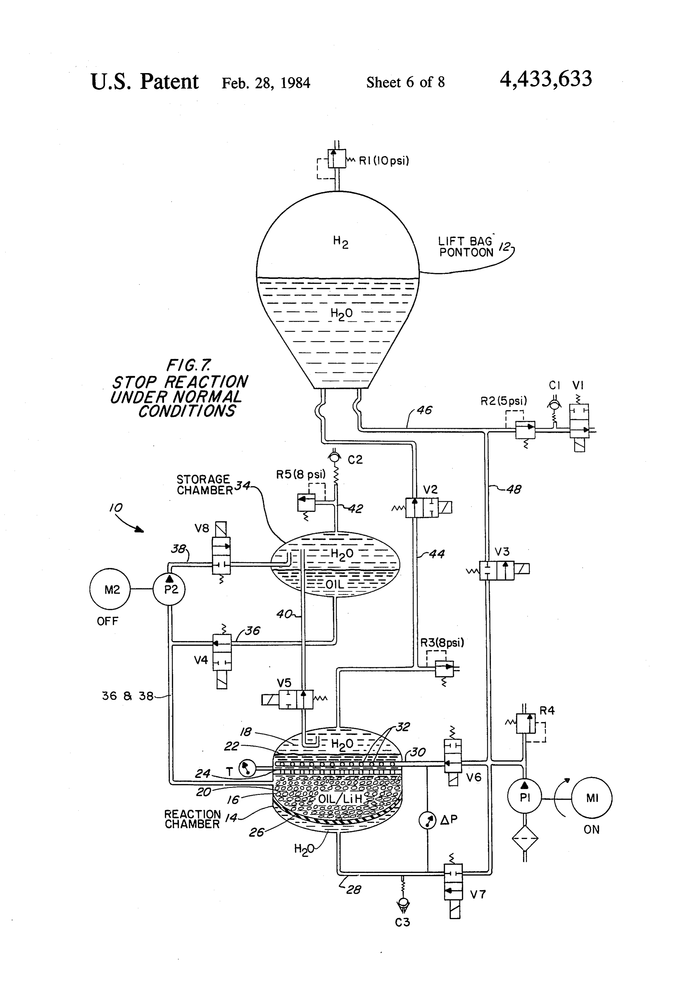
After descent to the bottom, the lift system is at causing the interfacial plane 22 to rise above the bed of tached to the object to be retrieved, as illustrated in lithium hydride and the reaction is stopped. By opening FIG.1. The lift bag is then completely filled with ballast 5 valves V2, V5 and V6 water enters the storage chamber water, as illustrated in FIG. 4. During this operation, 34 to take the place of the oil displaced therefrom, and pump P1 is operating, valves V3, V4, and V5 are open the excess water not required for displacement goes and valves V1, V2, V6, V7 and V8 are closed. The through valve V2 into the lift bag and out into ambient opening of valve V3 during the operation of pump P1 ocean water via valve V1.
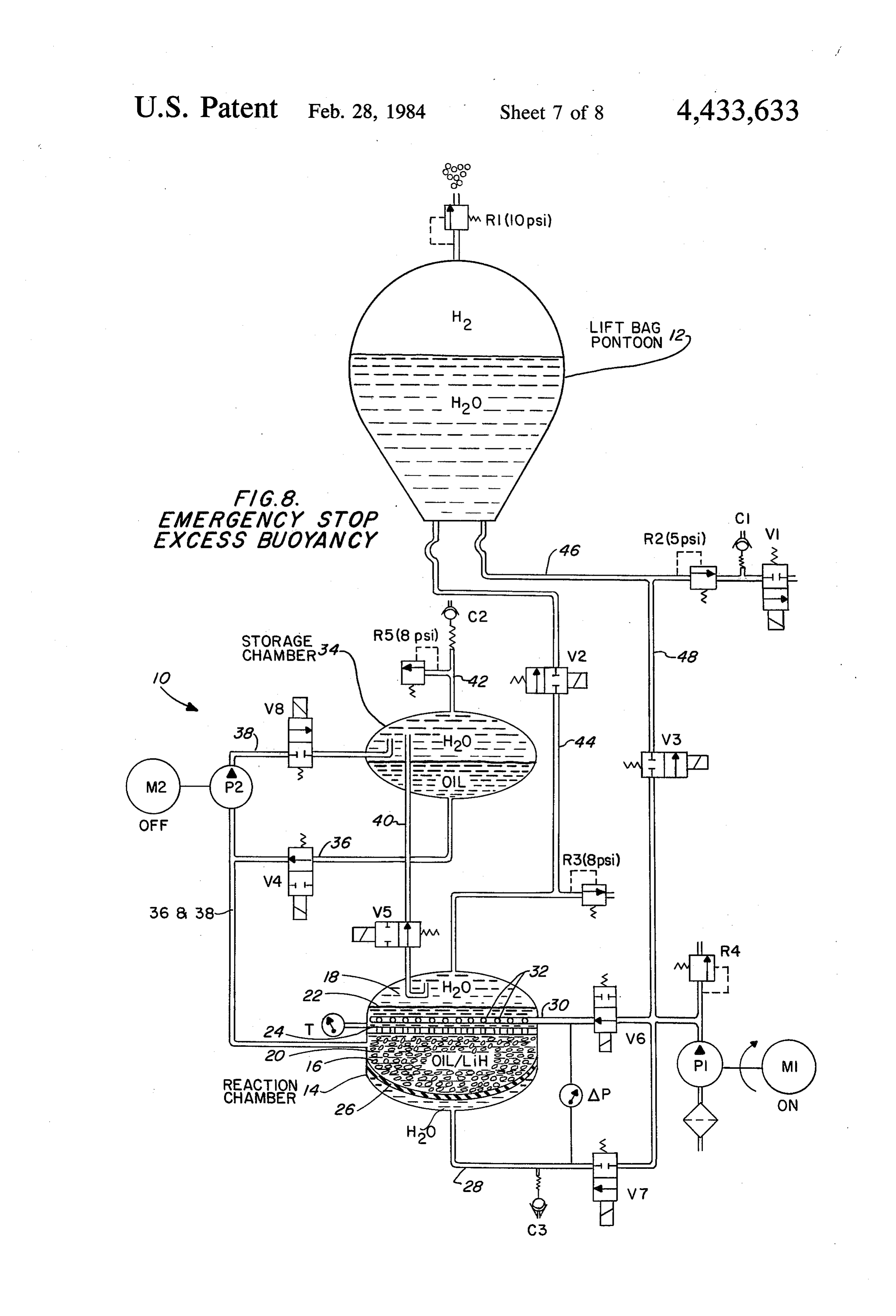
introduces the ballast water into the lift bag 12 via line O 48. Again, the valve V5 in its open position maintains EMERGENCY STOP EXCESS BUOYANCY equalization of pressure between the chambers 12 and Should the lift bag become excessively buoyant, the 34, and the opening of valve V4 ensures that chamber diver can bring about an emergency stop of the reaction 14 remains completely filled with oil. by operating the pumps and valves shown in FIG. 8. 5 During this operation, pump P1 is operating and pump
INITIATE REACTION P2 is off, valves V4 and V5 are open, and valves V1, After the attachment of the lift system to the object, V2, and V8 are closed. Valve V3 is pulsed intermit the diver then initiates a reaction which will cause the tently as desired to admit water to the lift bag to de generation of hydrogen gas. During this operation, crease its buoyancy, valve V7 may be pulsed intermit pumps P1 and P2 are operating, valves V1,V2, V6, and 20 tently to keep the diaphragm 26 high, and valve V6 may V8 are open and valves V3, V4, V5, and V7 are closed. be generally kept open but pulsed closed when valve By opening valve V1, the pontoon is readied for dis V7 is pulsed open to put pressure on the diaphragm. charging water via the relief valve R2, the opening of When valve V3 is pulsed to an open position, water will valve V2 readies the lift bag for receiving gas generated displace the hydrogen gas in the lift bag to decrease its by the reaction chamber 14, the opening of valve V6 25 buoyancy. With valve V4 open oil flows by gravity introduces water into the reaction chamber to cause a from the storage chamber 34 downwardly into the reac reaction with the lithium hydride, and the opening of tion chamber 14 to raise the interfacial plane 22 between valve V8 enables the oil 20 in the reaction chamber 14 the oil and the water above the bed of lithium hydride, to be pumped upwardly and into the storage chamber thus stopping the reaction. Oil displaced from the stor 34. In FIG. 5 it can be seen that the interfacial plane 22 30 age chamber 34 is replaced by water introduced between the water and the oil has dropped in the reac through valves V6 and V5.
tion chamber 14, but has not yet reached the bed of lithium hydride nodules 16. As soon as this interfacial - ASCENT plane reaches the bed of lithium hydride the water will Once the lift bag 12 has received enough hydrogen to react therewith and cause the generation of hydrogen 35 commence an ascent, the entire system is closed down, gas for displacing the water within the lift bag 12. as illustrated in FIG. 9. Only valves V4 and V5 are open
NORMAL REACTION
which allows the reaction chamber to be maintained full of oil via valve V4 and pressures to be equalized be
In FIG. 6, the interfacial plane 22 is shown slightly tween the chambers via valve V5. During this opera below the perforated member 24 which allows the tion, relief valve R1 at the top of the lift bag 12 will vent water to react with the lithium hydride and generate expanding gas from the lift bag as the entire system hydrogen gas. The operation as shown in FIG. 6 can be ascends in the water. The diaphragm 26 is shown considered to be a normal reaction for generating such moved upwardly to lessen the space between the dia gas. During this operation, pump P1 is operating and P2 phragm 26 and the perforated member 24 due to the is off, valves V1 and V2 are open, and valves V3, V4, 45 expenditure of the lithium hydride. V5, and V8 are closed. Valve V6 is normally open and If desired, all of the solenoid valves V1 through V8 valve V7 is normally closed but are occasionally pulsed could be automatically operated according to a com in the opposite directions to raise the diaphragm 26 and puter program, in which case a suitable microprocessor make the space between the diaphragm and the perfo could be utilized in combination with the generation rated member 24 smaller because of the expenditure of 50 system. Further, all of the solenoid valves V1 through the lithium hydride during the reaction. Also, P2 can be V8 could be replaced by manually operated on-off gate operated and valve V8 pulsed in an opposite direction if valves, however this substitution would be somewhat the oil level becomes too high in the reaction chamber more difficult for a diver to operate. 14 to maintain the desired reaction speed. Reaction Obviously, many other modifications and variations speed will also be indicated by the temperature gage T. 55 of the present invention are possible in the light of the The opening of valve V1 continues to allow the water above teachings. It is therefore to be understood that in the lift bag 12 to be displaced by the hydrogen, and within the scope of the appended claims the invention the opening of valve V2 enables the hydrogen to be may be practiced otherwise than as specifically de transferred between the reaction chamber 14 and the lift scribed.
bag 12. . . . What is claimed is:
STOP REACTION UNDER NORMAL
1. A gas generator comprising:
CONDITIONS a reaction chamber having top and bottom ends; a perforated member mounted transversely across the
Should the diver desire to stop the reaction in the entire reaction chamber for containing a reactant chamber 14, he would operate the pumps and valves as 65 material between the perforated member and one shown in FIG. 7. In this operation, pump P1 is operat end of the reaction chamber; ing and pump P2 is off, valves V1,V2, V4, V5 and V6 the reaction chamber being adapted to contain liquids are open, and valves V3, V7, and V8 are closed. By which have dissimilar specific gravities, one of the
Page 14
liquids being reactive with the reactant and another the specific gravity of the nonreactive liquid being of the liquids being nonreactive with the reactant, greater than the specific gravity of the reactive the reactive and nonreactive liquids having a mu liquid;
tual interface; - the storage chamber being located above the reaction means connected to the reaction chamber for selec chamber;
tively moving the interface of the liquids above or the first and second nonreactive liquid lines being below the perforated member; connected into the reaction chamber below the a resilient diaphragm mounted transversely across the perforated member, and the first nonreactive liquid reaction chamber; and line being connected through the bottom of the a line connected into the reaction chamber for intro O storage chamber;
ducing fluid on one side of the diaphragm so as to the second reactive liquid line being connected into reduce the volume between the diaphragm and the the top of reaction chamber. perforated member. 6. A gas generator as claimed in claim 5 including: 2. A gas generator comprising: the reactant material being located below the perfo a reaction chamber having top and bottom ends; 15 rated member and having a specific gravity less a perforated member mounted transversely across the than the specific gravity of the nonreactive liquid; and entire reaction chamber for containing a reactant the reactant material being in nodular form of a size material between the perforated member and one larger than the perforations in the perforated mem end of the reaction chamber; 20 - ber so that the nonreactive material buoys the nod the reaction chamber being adapted to contain liquids ules of reactant material up against the bottomside which have dissimilar specific gravities, one of the of the perforated member. . . . . liquids being reactive with the reactant and another 7. A gas generator as claimed in claim 6 including: of the liquids being nonreactive with the reactant, , the reactive and nonreactive liquids having a mu a diaphragm sealably connected across the reaction tual interface;
25 chamber below the perforated member; and a line connected into the bottom of the reaction means connected to the reaction chamber for selec chamber and having an outer end which is con tively moving the interface of the liquids above or nectable to a pump for introducing fluid into the below the perforated member, said means includ bottom of the reaction chamber to reduce the volu 1ng: 30 metric space between the diaphragm and the perfo a first reactive liquid line having a portion which rated member.
transversely extends into the reaction chamber in 8. A gas generator as claimed in claim 7 including: a spaced parallel relationship to the perforated the reactant being lithium hydride; member and having an outer end which is the reactive liquid being water; and adapted to be connected to a pump; 35 the nonreactive liquid being fluorocarbon oil. a nonreactive liquid storage chamber disposed at a 9. An apparatus as claimed in claim 8 including: level which is different than the level of the a lift bag pontoon having a top and a bottom when reaction chamber, the storage chamber having inflated;
top and bottom ends; a relief valve connected in the top of the lift bag; a first nonreactive liquid line interconnecting the 40 a water and gas line interconnecting the top of the reaction chamber on one side of the perforated reaction chamber to the lift bag; member with the nonreactive liquid storage a water discharge line connected to the bottom of the chamber for allowing the nonreactive liquid to lift bag;
flow by gravity between the chambers; a valve and a relief valve interconnected in series in a valve interconnected in the first nonreactive liq 45 the water discharge line; and uid line; a water intake line connected to the lift bag and hav a second nonreactive liquid line interconnecting ing an outer end which is connectable to a pump. the reaction chamber on the same side of the 10. A gas generator comprising:
perforated member with the nonreactive liquid a reaction chamber having top and bottom ends; storage chamber; and 50 a bed of reactant material disposed within the cham a pump and a valve interconnected in the second ber intermediate its top and bottom ends; nonreactive liquid line. liquids heated within the chamber, one of the liquids 3. A gas generator as claimed in claim 2 wherein the being reactive with the reactant and the other liq means for selectively moving the liquid interface fur uid being nonreactive with the reactant; ther includes: 55 the nonreactive liquid having a higher specific grav a second reactive liquid line interconnecting the reac ity than the reactive liquid so that the liquids inter tion chamber on an opposite side of the perforated face substantially along a cross-sectional plane of member with the nonreactive liquid storage cham the chamber whereby gas is produced when the ber; interfacial plane is vertically disposed on one side a third reactive liquid line connected through one end 60 of the bed of reactant material and gas is not pro of the storage chamber and having an outwardly duced when the interfacial plane is vertically dis extending portion; and posed on an opposite side of the bed of reactant an intake check valve and a relief valve intercon material;
nected in parallel in the outwardly extending por the reactant material being nodular and having a tion of the third reactive liquid line. 65 specific gravity which is less than the specific grav 4. A gas generator as claimed in claim 3 including: ity of the nonreactive liquid; the reactant material and the liquids. a perforated member mounted transversely across the 5. A gas generator as claimed in claim 4 including: reaction chamber and having perforations which
Page 15
are smaller in size than the size of the reactant the nonreactive liquid being fluorocarbon oil. material; W 15. A gas generator as claimed in claim 14 including: the reactant material being disposed in the nonreac the first reactive liquid line having a plurality of tive liquid so as to be buoyed up against the bottom openings therealong.
of the perforated member; and 5 16. An apparatus as claimed in claim 15 including: means for selectively adjusting the vertical position a water pump;
of the interfacial plane above or below the bed of a lift bag pontoon having a top and a bottom when reactant material so that gas can be selectively inflated;
generated. a relief valve connected into the top of the lift bag for 11. A gas generator as claimed in claim 10 wherein O venting expanding gas therefrom; the selective adjusting means includes: a water and gas line interconnecting the top of the a first reactive liquid line which has a portion which reaction chamber with the lift bag; extends transversely into the reaction chamber in a a discharge water line connected to the bottom of the spaced relationship above the perforated member lift bag and having an outer ambient end; and which has an outer end which is connectable to 15 a discharge valve interconnected in the bag discharge a pump. water line and a relief valve interconnected in the 12. A gas generator as claimed in claim 11 wherein same water line between the bottom of the lift bag the selective adjusting means further includes: and the discharge valve;
a nonreactive liquid storage chamber disposed above an intake water line interconnecting the pressure side the reaction chamber; 20 of the pump with the lift bag; and a first nonreactive liquid line interconnecting the a valve interconnected in the lift bag intake water reaction chamber below the perforated member line.
with the bottom of the nonreactive liquid storage 17. A method of generating gas comprising the steps chamber for allowing nonreactive liquid to flow by of:
gravity from the nonreactive liquid storage cham 25 providing a reaction chamber having a top and a ber to the reaction chamber; bottom with a perforated member mounted trans a valve interconnected in the first nonreactive liquid versely therein between said top and bottom; line; - disposing reactive and nonreactive liquids in the reac a second nonreactive liquid line interconnecting the tion chamber; the nonreactive liquid having a spe reaction chamber below the perforated member 30 cific gravity which is greater than the specific with the nonreactive liquid storage chamber; gravity of the reactive liquid; a pump and a valve interconnected in the second disposing reactant nodules in the nonreactive liquid nonreactive liquid line. . . . below the perforated member with a nodular size 13. A gas generator as claimed in claim 12 wherein which is larger than the size of the perforations in the selective adjusting means further includes: 35 the perforated member; and a second reactive liquid line interconnecting the reac selectively adjusting the levels of the liquids in the tion chamber above the perforated member to the proximity of the perforated member to generate nonreactive liquid storage chamber; gas.
a third reactive liquid line connected into the top of 18. A method as claimed in claim 17 including the the nonreactive liquid storage chamber and having 40 steps of:
an outwardly extending portion; and selectively disseminating reactive liquid into the reac an intake check valve and a relief waive intercon tion chamber above the perforated member. nected in parallel in the outwardly extending por 19. A method as claimed in claim 17 including the tion of the third reactive liquid line. steps of:
14. A gas generator, as claimed in claim 13 including: 45 selectively decreasing the chamber volume for the the reactant being lithium hydride; reactant as the reactant is : used2k up. the reactive liquid being water; and k . . k
Provenance
- Collection
- Cited prior art
- Original PDF
- patentimages.storage.googleapis.com →
- Filed
- 1982-04-16
- Pages
- 15
- Method
- pdftotext (the PDF's own text layer) + pdftoppm 300dpi page scans
- Source
- Google Patents bibliographic record
- Granted
- 1984-02-28
- Inventors
- Don W. Caudy; Donald J. Hackman; John R. Myers; Robert T. Hoffman; US Department of Navy
- Transcribed from
- patentimages.storage.googleapis.com →