patent · US4236989
Electrolytic cell
2 December 1980
Page 1 — bibliographic record
United States Patent (19) 11) 4,236,989 Dahlberg 45) Dec. 2, 1980 54 ELECTROLYTIC CELL Assistant Examiner-D. R. Valentine (75) Inventor: Lois A. Dahlberg, Corpus Christi, Attorney, Agent, or Firm-Richard M. Goldman Tex. 57 ABSTRACT (73) Assignee: PPG Industries, Inc., Pittsburgh, Pa. Disclosed is an electrolytic cell having an electrode pair of interleaved anode and cathode fingers with a syn (21) Appl. No.: 922,716 thetic separator, i.e., a permionic membrane or a micro 22 Filed: Jul. 7, 1978 porous diaphragm, therebetween. At least one of the
two electrodes of the electrode pair has a continuous
electrodic surface with fluid impermeable members at opposite ends of the continuous electrodic surface and a 52 U.S. Cl. .................................... 204/252; 204/256; synthetic separator sealably mounted at the fluid imper 204/258; 204/266; 204/283 meable surfaces and extending over the face of the elec 58) Field of Search ........................ 204/252, 263-266, trodic surface between the members of the electrode 204/256, 258, 283, 282 pair. The fluid impermeable members at the opposite 56) References Cited ends of the continuous electrodic surface may either be
as compressive masks, at opposite edges of the finger 3,809,630 5/1974 De Nora et al. ................ 204/263 X like electrode sheets, maintaining the separator against 4,013,536 3/1977 Carbaraux ............................ 204/266 the finger-like electrode sheet, and providing an elec 4,036,727 7/1977 Rahn ................................ 204/254 X trolyte-tight seal therebetween. 4,056,459 11/1977 Ritti et al. ........................ 204/256 X
Primary Examiner-John H. Mack 7 Claims, 10 Drawing Figures
Page 2
Drawing sheet — no readable text.
Page 3
Drawing sheet — no readable text.
Page 4
Drawing sheet — no readable text.
Page 5
Drawing sheet — no readable text.
Page 6
Drawing sheet — no readable text.
Page 7
odic element of the monopolar electrolyzer includes a
ELECTROLYTIC CELL valve metal coating or surface on an internal element of either a peripheral wall or the cell bottom and coated
BACKGROUND OF THE INVENTION valve metal fingers extending outwardly therefrom.
Aqueous alkali metal halide brines are electrolyzed to The anodic and cathodic half cells are assembled to yield chlorine and alkali metal hydroxide, e.g., caustic form an electrolytic cell with the anodes facing the soda or caustic potash. One method of electrolysis pro cathodes and substantially parallel thereto with a sub ducing an alkali metal hydroxide cell liquor is in an stantially uniform space, i.e., an interellectrode gap, electrolytic cell having the anode separated from the therebetween. Additionally, a synthetic separator is cathode by a permionic membrane. Another method of 10 positioned between the anode and cathode dividing the electrolysis producing a cell liquor of alkali metal hy cell into a catholyte compartment and an anolyte com droxide and alkali metal chloride is in an electrolytic partment.
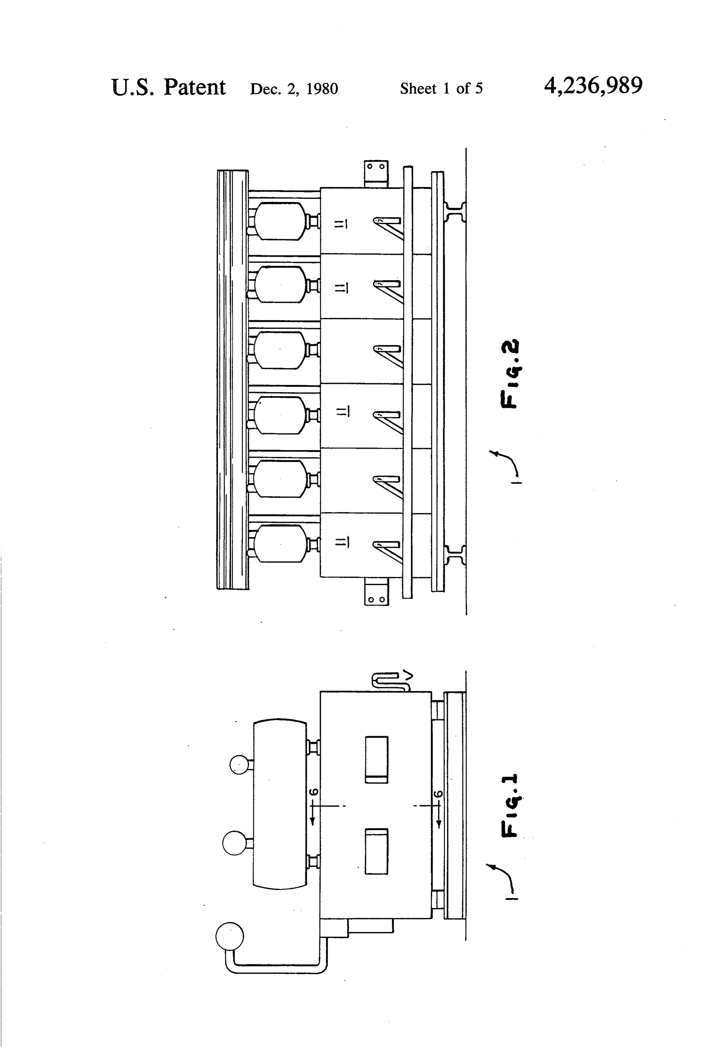
cell having a synthetic microporous diaphragm be One problem encountered in electrolytic cells having tween the anode and the cathode. synthetic separators is mounting the separator on an In an electrolytic cell having the anolyte separated 15 electrode. This becomes a critical problem when there from the catholyte by a separator, alkali metal chloride are interleaved electrodes of complex shapes. brine is fed to the anolyte compartment and chlorine is Synthetic separators, that is, synthetic halocarbon evolved at the anodes. This gives rise to a froth of chlo resins which may have acid groups thereon as exempli rine gas and depleted brine which is recovered from the 20 fied by fluorocarbon resins with carboxylic acid groups, cell, separated into gaseous chlorine and liquid brine fluorocarbon resins with sulfonic acid groups, and fluo fractions with the brine returned to the cell. Addition rocarbon resins with various derivatives of the afore ally, depleted brine may be recovered from the cell, mentioned resaturated, and returned to the cell. Alkali metalion is to join andgroups as well as other groups, are difficult require special assembly methods. These transported through the synthetic separator to the cath special assembly methods include chemical reactions at olyte compartment where hydrogen and alkali metal 25 the laps and joints, heating, and compression. hydroxide are produced. Water may be added to the According to the invention herein contemplated, the catholyte compartment to control the alkali metal ion content of the catholyte liquor, in this way controlling use of synthetic separators at electrolytically less active, the efficiency of the cathode reaction. complex shaped areas of the electrode are dispensed The electrolytic cell may be in the form of one of a 30 with thereby allowing the use of separators of simple plurality of cells in a bipolar electrolyzer or the electro shape. This is accomplished by providing electrolyte lytic cell may be monopolar cell. In a bipolar electro impermeable members at opposite ends of the electrode, lyzer, a plurality of bipolar units are electrically and to hold the permionic membrane in place. The electro mechanically in series with the cathodes of one individ lyte impermeable members may be the cell top and cell ual electrolytic cell and the anodes of the next adjacent 35 bottom or they may be flanges or the like held in com electrolytic cell of the electrolyzer being mounted on a pression at opposite ends of the electrode. common structural unit, a bipolar unit. The bipolar unit THE FIGURES includes a backplate having a catholyte-resistant mem ber and an anolyte-resistant member. FIG. 1 is a front elevation view of a bipolar electro The cathodic side of the bipolar unit contains a screen lyzer.
spaced from the steel backplate and defining a volume FIG. 2 is a side elevation view of a bipolar electro therebetween and hollow cathode fingers extending lyzer.
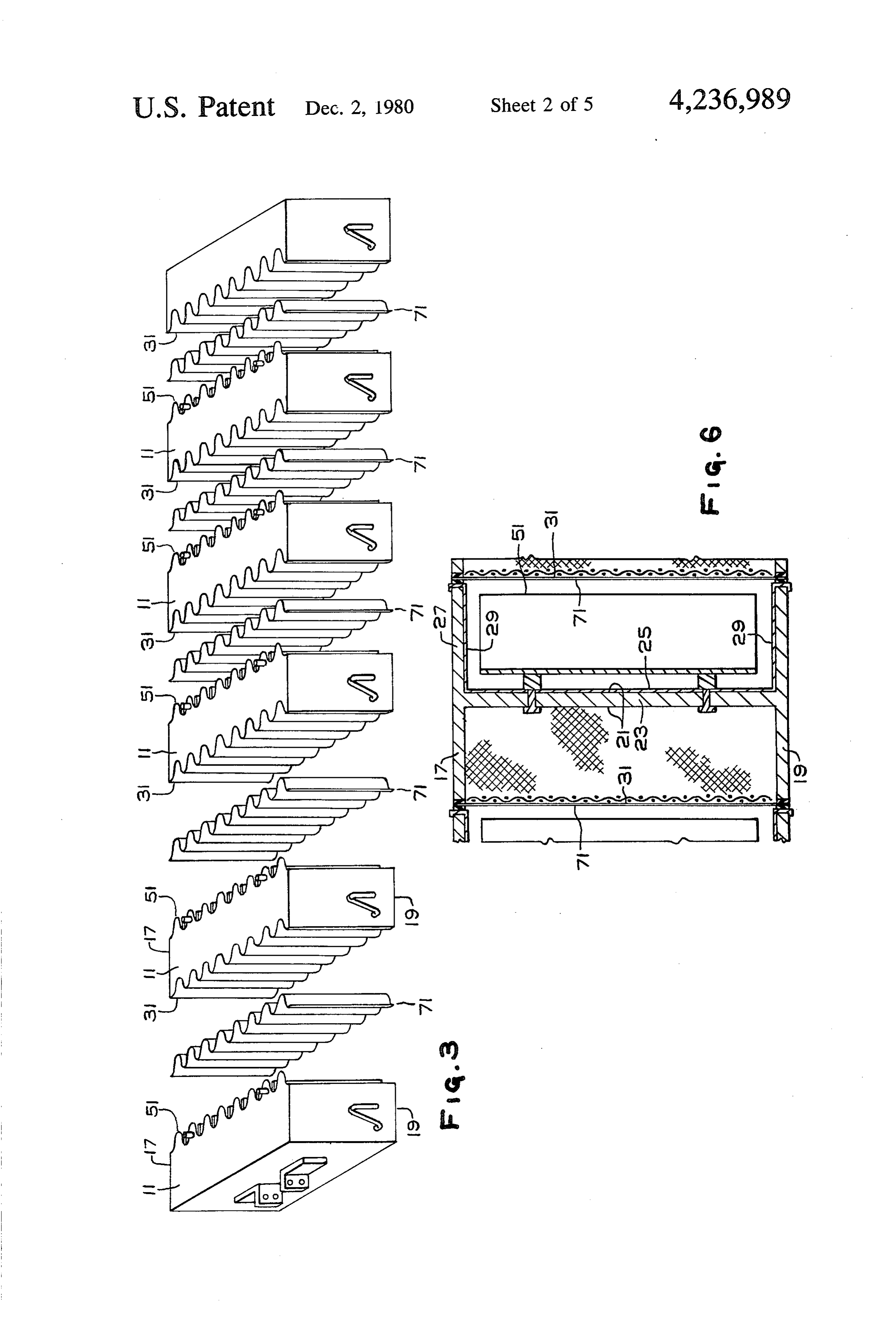
outwardly from the backplate. The volume within the FIG. 3 is an exploded view of a bipolar electrolyzer hollow cathode fingers and the volume between the showing bipolar elements, terminal electrodes, and syn screen and the backplate define the catholyte volume. 45 thetic separators.
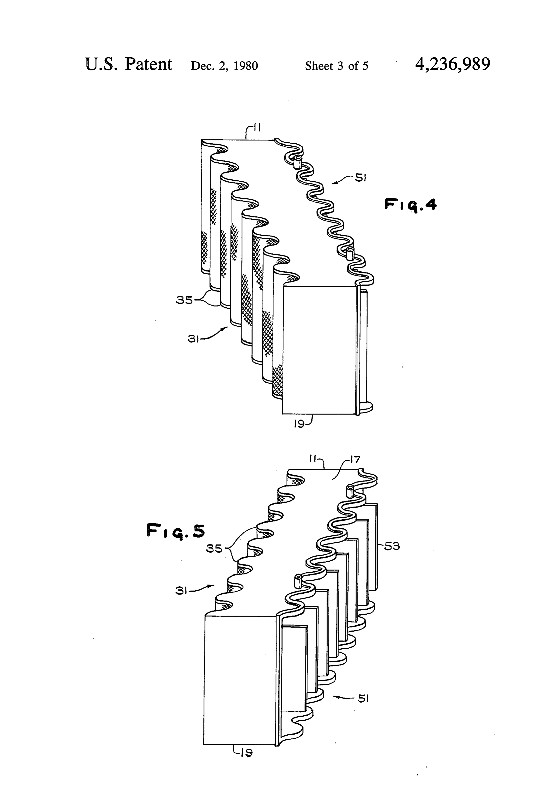
The anodic side of the bipolar unit includes a valve FIG. 4 is an isometric view of a bipolar unit showing metal backplate with coated valve metal fingers extend the cathodic side.
ing outwardly therefrom, substantially parallel to the cathode fingers. The adjacent bipolar units are assen theFIG. 5 is an isometric view of a bipolar unit showing anodic side.
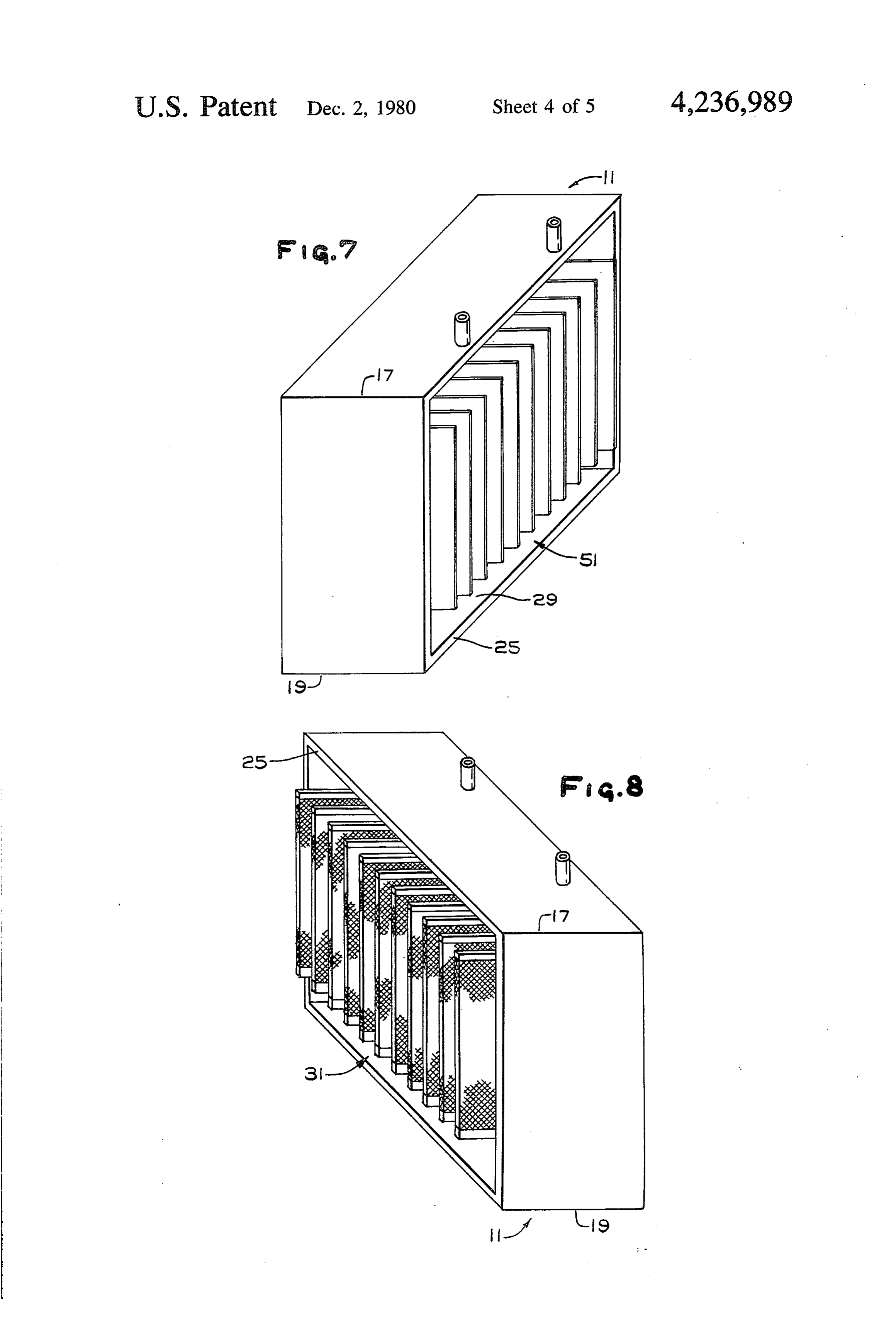
bled together to form an electrolytic cell with the an 50 FIG. 6 is a cutaway side elevation of a bipolar unit. odes of one bipolar unit facing the cathodes of the next FIG. 7 is an isometric view of a bipolar unit prepared adjacent bipolar unit and substantially parallel thereto according to an alternative exemplification. with a substantially uniform space, i.e., interelectrode FIG. 8 is an isometric view of the bipolar unit shown gap, therebetween. Either a synthetic permionic mem brane or a synthetic microporous diaphragm is posi 55 in FIG. 7.
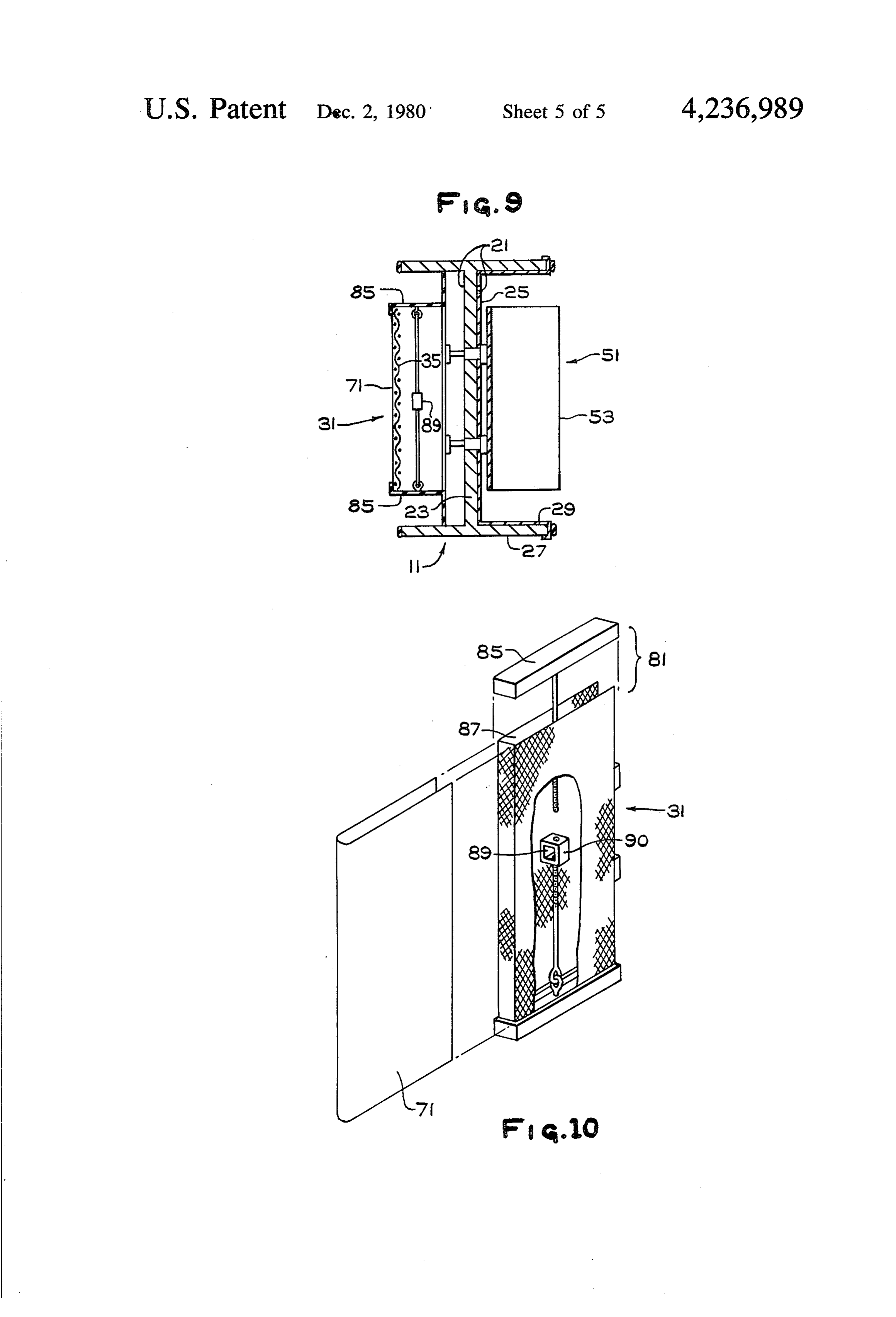
tioned between the anode and cathode, dividing the cell shown FIG. 9 is a cutaway side elevation of the bipolar unit into a catholyte compartment and an anolyte compart in FIGS. 7 and 8.
et. FIG. 10 is an exploded view of an electrode useful in A bipolar electrolyzer, as described hereinabove, the bipolar unit shown in FIGS. 7, 8, and 9. may contain anywhere from two to a hundred or more 60 DETAILED DESCRIPTION OF THE individual electrolytic cells in the electrolyzer. INVENTION Alternatively, the electrolysis may be carried out in a monopolar cell. A monopolar cell has a cathodic half A bipolar electrolyzer 1 is shown generally in FIGS. cell containing a screen spaced from an outside wall and 1, 2, and 3. The bipolar electrolyzer 1 includes a plural defining a volume therebetween and hollow cathode 65 ity of bipolar units 11 electrically and mechanically in fingers extending outwardly therefrom. The volume series with cathodes 31 of one individual electrolytic within the hollow cathode fingers and between the cell and the anodes of the next adjacent electrolytic cell screen and backplate is the catholyte volume. The an 15 of the electrolyzer being mounted on a common
Page 8
structural member, i.e., the backplate 21 of the bipolar preferred because of its commercial availability. The unit 11. - anodes 53 further include a surface material of a suitable An individual electrolytic cell 15 is defined by the electrocatalyst, that is, a material that allows electron anodic side 51 of one bipolar unit 11, the cathodic side transfer and catalyzes the evolution of molecular chlo 31 of the next adjacent bipolar unit 11, and a permionic .
membrane 71 interposed therebetween. The bipolar electrolyzer 1 is assembled to form indi The bipolar unit 11 includes a backplate 21 having a vidual electrolytic cells 15 with the anodes 51 of the cathodic side 31 and an anodic side 51. The backplate bipolar unit 11 facing the cathodes 31 of the next adja- . 21, shown especially in FIGS. 6 and 9, has a steel plate cent bipolar unit 11 such that the anodes 51 are substan 23 which is a primary structural member of the bipolar 10 tially parallel to the cathodes 31 with a substantially unit 11, and a steel body 25 having peripheral walls 27 uniform space, i.e., interelectrode gap, therebetween. around both the cathodic 31 and anodic sides 51 of the A synthetic separator 71 is positioned between the bipolar unit 11. The steel plate 23 and steel body 25 are anode elements 53 and cathode elements 35, dividing lined with a valve metal sheet 29 on the anodic side of the cell 15 into an anolyte compartment and a catholyte the bipolar unit. The steel plate 23 is of a thickness of 15 compartment. The synthetic separator may be either a from about 1.0 centimeter to about 3.0 centimeters and permionic membrane, permeable to the flow of cations the valve metal sheet 29 may be of a thickness of from and impermeable to the flow of anions, or a micropo about 2 to about 5 millimeters. rous diaphragm permeable to the flow of electrolyte. The cathodic side 31 of the bipolar unit 11 includes a The electrode structure herein contemplated may screen 33 spaced from the steel backplate 23 and defin 20 also be used in monopolar cells. Monopolar cells in ing a volume therebetween. The cathodic side of the clude a cathodic half cell with a screen spaced from an bipolar unit also has hollow cathode fingers 35 extend outside wall and defining a volume therebetween and ing outwardly from the steel plate 23 of the bipolar unit hollow cathodic fingers extending outwardly from the 11 and from the screen 33. The volume within the cath screen. The volume within the hollow cathodic fingers ode fingers 35 and between the screen 33 and backplate 25 and between the screen and wall define the catholyte 23 defines the catholyte volume. volume. The screen and cathode fingers are fabricated The material used in fabricating the screen 33 and the of the same materials as described with reference to a cathode fingers 35 is a perforate or foraminous sheet or bipolar electrolyzer and are shaped generally with plate which may be inward and upward louvered. The round edges on the cathode providing a wave form, for material may be wire, screen, ribs, bars, rods, perforated 30 example, a continuous wave of the cathodes to cathode plate, perforated sheet, or the like. The fingers 35 and screen. Alternatively, individual rectangular or even screen 33 are fabricated out of material that is electri truncated tetrahedral cathode fingers may be used espe cally conductive and substantially chemically resistant cially where the cathode fingers are individually re to concentrated alkali metal hydroxides and hydrogen movable.
under cathodic conditions. Such materials include iron, 35 The anodic side is formed of a valve metal, as de steel, cobalt, nickel, alloys of iron with cobalt and scribed above. The anode fingers may be in the form of nickel, and carbon, such as stainless steel, and copper. waves or blades. The waves or blades are substantially Additionally, the cathodic elements may have a suit parallel to the cathode fingers and spaced substantially able catalyst, for example, an electron transfer catalyst uniformly therefrom. The anode elements themselves or hydrogen evolution catalyst, thereon. are formed of the same materials as described herein The cathode elements, i.e., the cathode fingers 35, are above with respect to bipolar electrolyzers and are normally rounded so as to provide a wave form, for assembled together to form an electrolytic cell with the example, a continuous wave of cathode fingers, such as anodes facing the cathodes, substantially parallel sinusoidal wave cathode fingers when looking at the thereto and spaced uniformly therefrom. A synthetic cathodes directly above. Alternatively, the cathode 45 separator is spaced therebetween, dividing the cell into fingers 35 may be individual polyhedrons or even trun a catholyte compartment and an anolyte compartment. cated pyramidal cathode fingers 35, especially when the The mounting of the synthetic separator 71 presents fingers 35 are individually removable from the cathode special problems in an electrolytic cell having inter Screen 33. leaved electrodes of complex shape. The synthetic sepa The anodic side of the bipolar unit includes a valve 50 rator 71 between the anolyte compartment and the metal sheet 29 on the backplate 21 and coated valve catholyte compartment is a thin film, e.g., from about metal fingers 53. The fingers 53 may be blades substan 0.1 mm to about 0.5 mm. It is fabricated of a synthetic tially parallel to the cathode fingers. Alternatively, the halocarbon resin having acid groups thereon. The syn anodic elements may be in wave form, for example, thetic separator material is a halogenated polymer hav sinusoidal, when looked at from above, substantially 55 ing pendant acid groups. Most commonly, the polymer parallel to and complementary with the cathode waves is a highly fluorinated polymer having pendant sulfonic, 35. carboxylic or sulfonamide groups. Such materials are One physical form of the anode elements 53 is a per normally supplied as sheets or rolled sheets of material. forate or foraminous sheet or plate, for example, inward These highly fluorinated polymers having acid groups and upward louvered mesh or screen or sheet or plate, 60 require special handling in order to join the sheets to or alternatively, bars, rods, ribs, wires, or the like. gether. Such special handling includes reaction to form The anode elements 53 are normally fabricated of a low melting derivatives prior to bonding followed by valve metal, that is, a metal that forms a protective further reaction to form ion exchange active forms after oxide coating upon exposure to acidic media under bonding or joining, chemical reactions to put bondable anodic conditions. Such materials include titanium, 65 groups thereon, heating, and compression at high pres vanadium, zirconium, columbium, hafnium, tantalum, SS.
and tungsten. Most commonly, titanium, tantalum, and It has now been found advantageous to eliminate the their alloys are used with titanium being particularly permionic membrane at electrolytically less active areas
Page 9
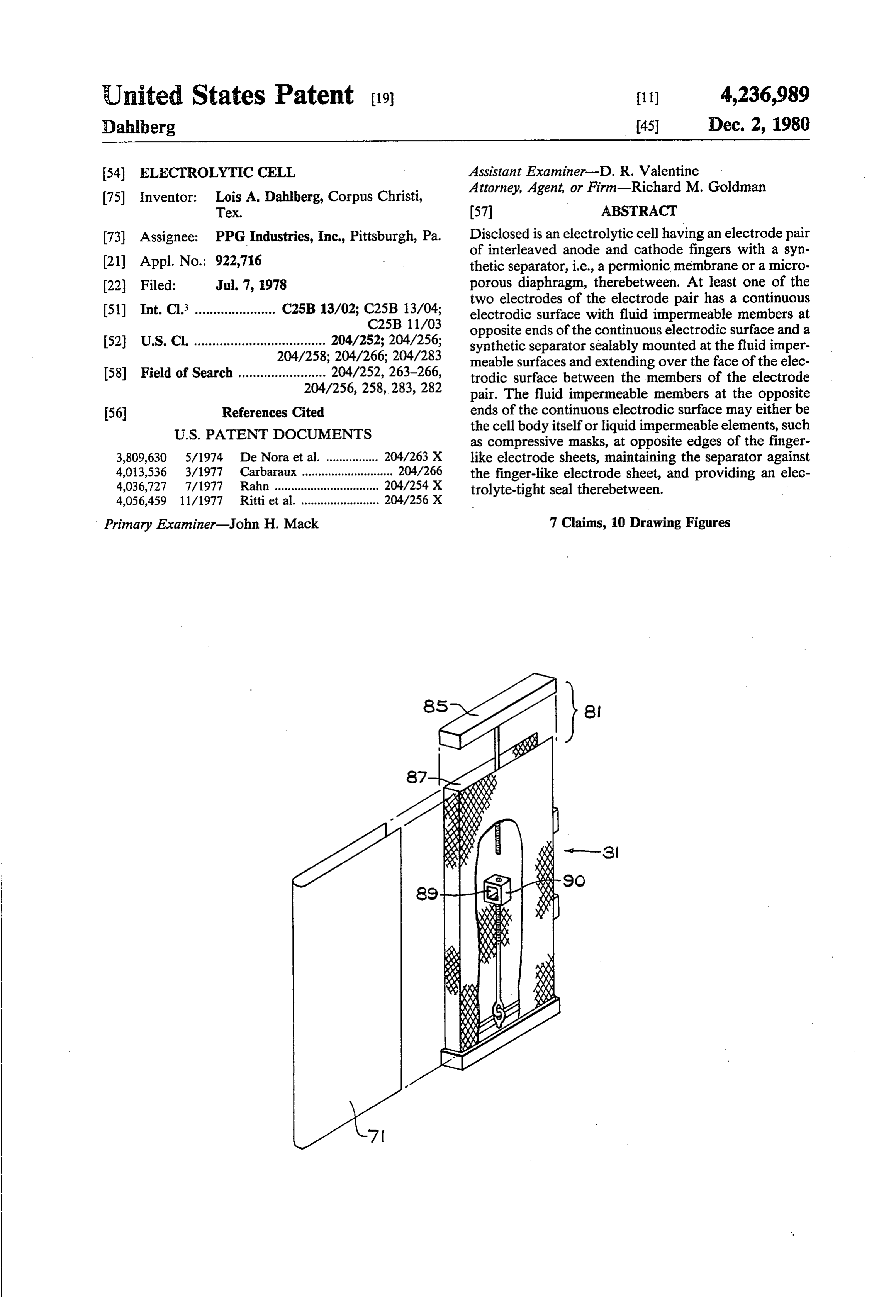
of the electrode. Electrolyte impermeable members are tive head on the cathode, while when the separator 71 is provided at opposite ends of the electrode holding the on the anode 53 the cell operates with a positive head on permionic membrane in place. These members may be the cathode and a negative head on the anode. provided at the cell top and bottom or by flanges or The separator 71 extends from the top of the elec blanks held in compression at the top and bottom of the trode to the bottom of the electrode, preferably fitting electrode within the cell. under the impermeable member 85 and being held in While this invention is described with reference to compression between the lip 37 of the electrode 35 and the separator being on the cathode, it is to be under the impermeable member 85. In this way, an electrolyte stood that the separator may be on either the anode or tight seal is maintained between the electrode 35, the the cathode or on both electrodes. Synthetic separators O separator 71, and the impermeable member 85, i.e., the may be mounted nearer the anode than the cathode and Cap.
even on the anode whereby to effect certain advan According to a preferred exemplification, the imper tages. meable member 85 has a lip 87 corresponding to the In the electrolytic cell 1 herein contemplated, there is contour of the open surface 39 of the electrode 35 an electrode pair of fingered, interleaved anodes 51 and 15 whereby to further seal the joint. cathodes 31. At least one member of the electrode pair The bipolar electrolyzer shown in FIGS. 7, 8,9, and has an electrode sheet which is preferably either 10 includes bipolar units 1 having anodic elements 51 smoothly continuous, for example, as a wave form sheet with anode blades 53 and cathodic elements 31 with shown in FIGS. 3, 4, 5, and 6, or disontinuous in planar cathode screen 33 and cathode fingers 35 extending ity, as, for example, truncated polyhedral as shown in 20 outwardly from the cathode screen 33 and the bipolar the electrode fingers in FIGS. 7, 8, 9, and 10. backplate 21.
The electrode has fluid impermeable members 81 at The separator 71 rests upon one of the electrodes opposite sides, that is, edges or ends or top and bottom with an electrolyte impermeable member 85 at the top of the electrode sheet. The synthetic separator 71 is held and bottom of the electrode. The electrolyte imperme on the electrode by the electrolyte impermeable mem 25 able member 85 may also be a compressive member bers 81. The separator 71 may either lay on the elec held in compression with a turn buckle 89 and bolt 90 trodic surface or be spaced therefrom, e.g., by gaskets, whereby to provide an electrolyte tight seal between spacers, nets, mesh, rods, insulators, or the like. the impermeable member 85, the separator 71, and the The use of the impermeable members at the extremi electrode 35.
ties of the electrodes allows for a single sheet of separa While the invention has been described with respect tor without resin-to-resin seals, especially at stress 30 to certain exemplifications and embodiments thereof, it points where there is bending or turning of the mem is not meant to be limited except as in the claims ap brane such as tops, bottom, and leading edges of elec pended hereto.
trodes. This avoids chemical, thermal, and hydrostatic I claim:
working of the membrane at such joints. 1. An electrolytic cell comprising an anode and cath FIGS. 3 to 6 inclusive show one exemplification of 35 ode electrode pair of intermeshed vertical electrode the electrolytic cell of this invention where the cell surfaces with a synthetic separator therebetween, at body functions as the electrolyte impermeable member. least one member of said electrode pair having a contin The electrode 35 extends from the top 17 of the cell uous electrodic surface with horizontally disposed fluid body to the bottom 19 of the cell body, and the cell impermeable members at the top and bottom of said body follows the contour of the electrode. 40 continuous electrodic surface and synthetic separator The separator extends from the cell top 17 to the cell being sealably mounted at said impermeable members. bottom 19 and from one side of the cell to the opposite 2. The electrolytic cell of claim 1 wherein said syn side of the cell, preferably as an unbroken, single sheet. thetic separator (permionic membrane) is joined to said However, laps, for example, with a gasket or other electrode at a compression seal between said electrodic alternative compressive means, may be used. 45 surface and said fluid impermeable members whereby The electrolyzer 1 has bipolar units 11 with anodic to provide a fluid impermeable seal therebetween. elements 51 and cathodic element 31 separated by a 3. The electrolytic cell of claim wherein sain syn synthetic separator 71. The anodic element 51 includes thetic separator is joined to said electrode at a compres anodes 53 and anode connectors connecting the anodes sion seal between said electrodes.
53 to the backplate 21 of the bipolar unit 11 and thence 50 4. The electrolytic cell of claim wherein the elec through the backplate 21 to the cathodic element 31 of trode having the continuous electrodic surface is the the bipolar unit 11. The anodic side of the bipolar unit cathode and the synthetic separator in nearer the cath has a titanium lining 29 covering the steel body 25 as ode.
described hereinbove. 5. The electrolytic cell of claim wherein the elec The cathodic unit 31 includes cathode fingers 35 and 55 trode having the continuous electrodic surface is the cathode screen 33 spaced from the backplate 21 of the anode and the synthetic separator is nearer the anode. bipolar unit 11 and providing an electrolyte volume 6. The electrolytic cell of claim 5 wherein the syn therein. thetic separator rests on the anode. The synthetic separator 71 is interposed between the 7. An electrode assembly comprising: anode 53 and the cathode 35, for example, with suitable, 60 a foraminous, metallic, electrode sheet suitable for deformable gaskets 91 at bearing surfaces 93 and 95. intermeshing with a complimentary electrode According to an alternative exemplification, a remov sheet;
able member 85 on the electrode may function as the a synthetic separator on the outer surface of the elec liquid impermeable member. In this exemplification, the trode sheet; and electrodes do not extend from the top of the cell to the compressive means at the top and bottom of said bottom of the cell but rather begin above the cell bot 65 electrode sheet, maintaining said synthetic separa tom and terminate below the cell top. For example, tor against said electrode sheet and providing an when the membrane 71 is on the cathode 35, the cell electrolyte tight : seal: therebetween.
operates with a positive head on the anode and a nega
Provenance
- Collection
- Cited prior art
- Original PDF
- patentimages.storage.googleapis.com →
- Filed
- 1978-07-07
- Pages
- 9
- Method
- pdftotext (the PDF's own text layer) + pdftoppm 300dpi page scans
- Source
- Google Patents bibliographic record
- Granted
- 1980-12-02
- Inventors
- Lois A. Dahlberg; PPG Industries Inc
- Transcribed from
- patentimages.storage.googleapis.com →