patent · US2201965
Process for converting liquid hydrocarbon into gaseous fuel
21 May 1940
Page 1
Drawing sheet — no readable text.
Page 2
Drawing sheet — no readable text.
Page 3
Patented May 21, 1940 2,201.965
PROCESS FOR CONVERTING LIQUID HY
DROCARBON INTO GASEOUS FUEL
John T. Cook, Earl Gray, Saskatchewan, Canada
Application December 30, 1937, Serial No. 182,517
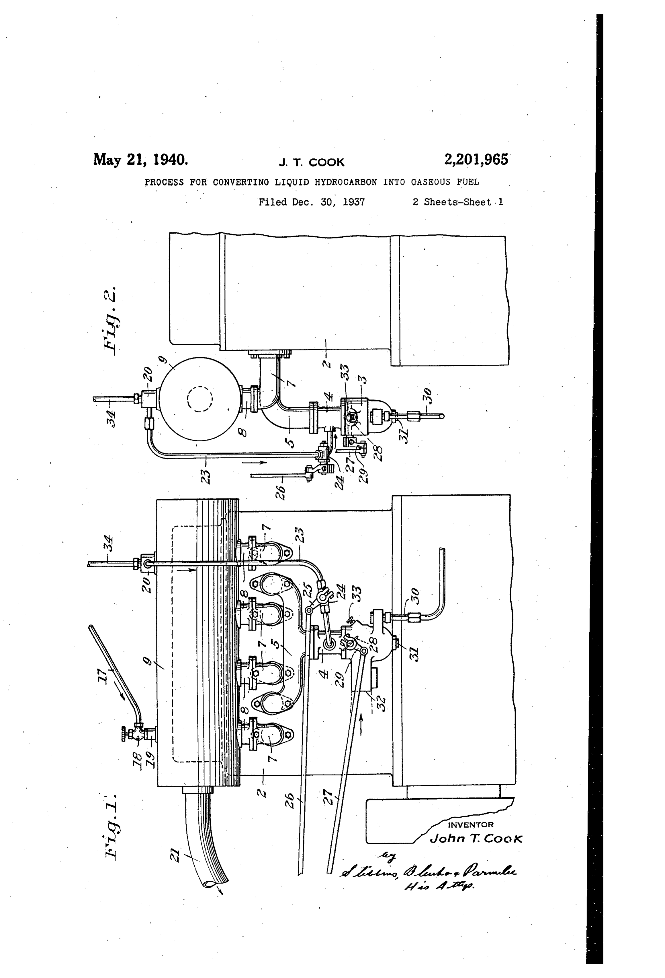
This invention relates to a process for cracking ing drawings, there is shown an internal com and rearranging the molecules of liquid hydro bustion engine designated by the reference nu Carbon compounds So as to obtain from then a meral 2. The engine is provided with any usual combustible gas suitable for the operation of an or suitable type of carburetor 3 which is con internal combustion engine or for other uses. The nected by a passage 4 to the intake manifold 5 of cracking of the liquid hydrocarbon into gaS may the engine which supplies the mixture of fuel be carried out either under partial vacuum or and air to the engine in a manner which is well under a pressure of from zero to 600 pounds per known.
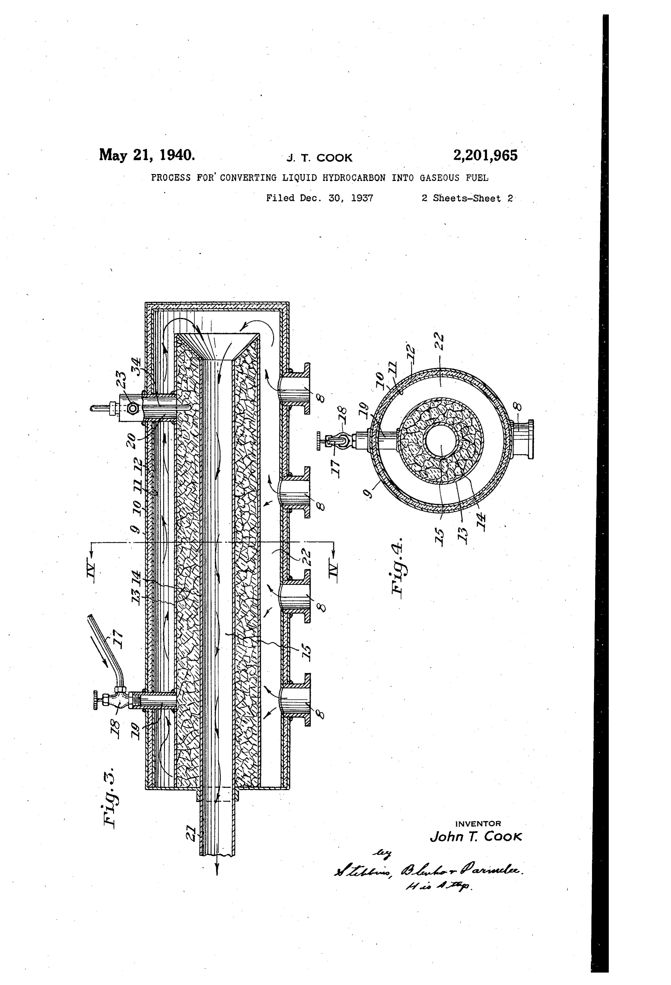
square inch. The cracking or conversion or re The engine is provided with exhaust passages arrangement of the molecules of the liquid hydro for the products of combustion from the engine. carbon is carried out in the presence of a catalyst, These passages are connected by vertical pas which aids in the rearrangement of the molecules. sages 8 to a reaction chamber designated by the in carrying out the reaction, the liquid hydro reference numeral 9 and shown in detail in Fig carbon fuel is preferably heated to a temperature res 3 and 4. The reaction chamber is formed s of 400 to 1200° C. of double walls 0 and having heat insulat 65 Although the invention is applicable to other ing material 2 therebetween in order to form uses as will be hereinafter more fully explained, it an outer heat insulating casing. Located inside Will be described herein more particularly as ap of the outer casing is a double walled annular plied to the conversion of a liquid hydrocarbon catalyst chamber having an outer Wall 3 and an into a gaseous hydrocarbon adapted for use as inner Wall 4 Spaced from each other and provid 3. fuel for an internal combustion engine. I may, ing a passage 5 through the interior of the 2 for example, convert fuel oil or distillate into catalyst chamber. The catalyst chamber is filled gaseous hydrocarbons in which the molecules of with a catalyst which aids in conversion of the the gaseous hydrocarbon have been produced by heavier hydrocarbon fuel into gaseous hydrocar cracking or rearranging the molecules of the fuel bons during the Cracking process. A suitable 25 oil or distillate. The gaseous hydrocarbons pro catalyst material is nickel ammonium sulphate. duced in accordance with my invention remain A saturated solution of nickel ammonium sul in the gaseous phase at atmospheric temperature phate may be applied to an inert carrier material and pressure. As an example, the composition of such as ground brick or calcined clay and the
one sample of gaseous hydrocarbons produced in carrier material thoroughly dried. The catalyst 30 accordance with my invention is: chamber is preferably made of steel or iron, it Per cent having been found that the combined catalytic
Hydrogen.------------------------------- 5.8 effect of the nickel ammonium sulphate and iron Olefins---------------------------------- 52.2 is very effective in aiding the cracking operation. Saturates-------------------------------- 48 I may use other nickel compounds as catalysts, CO, CO2, H2S----------------------------- 0.2 or may use cobalt or other metals of group VII The invention will now be described, by way of of The the periodic table or their compounds.
example only, in connection with an internal pipe f fuel to be cracked is supplied through a from any suitable source such as a gravity combustion engine in which the products of com feed fuel tank or a vacuum fuel tank, or the fuel 40 40 oustion of the engine are utilized for cracking the may be supplied under pressure of 0 to 600 pounds liquid hydrocarbon into gaseous hydrocarbons. per square inch. The flow of fuel is controlled In the accompanying drawings which illustrate by a valve 8 and is supplied through an inlet 9 the present preferred embodiment of my inven to the catalyst chamber. The fuel to be cracked tion, flows from left to right through the catalyst 45 Figure 1 is a side elevation of an internal con chamber, as viewed in Figure 3, and the cracked bustion engine, a cracking chamber and associ vapors flow through an outlet 20 and from there
Figure 2 is a front elevation of the apparatus are led back to the engine in a manner which shown in Fig. 5; Will be described more fully hereinafter. 50 Figure 3 is a longitudinal vertical Section, to The products of combustion from the engine 50 an enlarged scale, showing the cracking chamber, flow into the interior of the reaction chamber and through the inlet openings 8, and then circulate around the catalyst chamber flowing both in the
Figure 4 is a vertical section taken on the line
WV of Fig. 3. space between the catalyst chamber and the outer is Referring more particularly to the accompany casing and in the passage 5 which extends
Page 4
through the center of the catalyst chamber. The passages 8 and flow, as previously described, passage 5 is connected by an exhaust pipe 2 through the reaction chamber.
to a muffler. It will be noted that the products The Outlet passage 20 for the cracked gas is of combustion, in flowing through the space 22 provided with a thermocouple 34 which is con between the catalyst chamber and the outer nected to a heat indicator, not shown, thereby casing, flow concurrent with the flow of fuel in enabling the operator to determine when the re the catalyst chamber. Thereafter when the action chamber has been heated to a sufficiently products of combustion are flowing through the high temperature.
passage 5, they flow countercurrent to the flow upWhen the reaction chamber has been heated to the proper point, say from 400° C. to 1200° 0 0 of fuel in the catalyst chamber. Furthermore C. depending upon the particular fuel which the products of combustion are supplied to the chamber 22 through a plurality of inlet openings is to be Cracked, the valve 8 is opened and the which are spaced along the major part of the needle valve 33 is closed. The valves 8 and 33 chamber 22. Thus the fuel in the catalyst cham may be interlocked so that when one of them is 5 ber is first heated by the products of combustion opened the other is closed, thus making automatic 5 entering through the left hand inlet 8, and are the Switch-over from regular gasoline employed thereafter subjected to more intense heating due during the starting, to cracked gas employed to the products of combustion entering the inlets thereafter. After the valve 8 has been opened which are located farther toward the right hand and the valve 33 closed, the engine operates on 20 end of the cracking chamber. It has been found the cracked gas. The cracked gases are mixed 20 that the arrangement shown is particularly ef With the air in the mixing chamber 4 and then ficient in rapidly heating the fuel to cracking Supplied to the engine. .
temperature so that the vapor phase cracking of The Suction stroke of the engine pistons creates the fuel into gaseous hydrocarbons may be rapidly a partial vacuum in the mixing chamber 4 for carried out. drawing a mixture of fuel and air into the cylin 25 The gases from the catalyst chamber are led ders. This creates a partial vacuum in the cata by pipe 23 to mixing chamber 4 where they are lyst chamber since it is in communication with mixed in the right proportion with the air and the chamber 4 through the pipe 23. This partial admitted to the engine cylinders through intake Vacuum aids in causing the heavier hydrocarbon 30 manifold 5. The pipe 23 is provided with a fuel to flow through the catalyst chamber and 30 throttle valve 24 having a throttle valve lever 25aids in the vapor phase cracking of such fuel. It and a throttle lever 26 which is connected to a . will be noted that a temperature is employed such governor or hand accelerator pedal, not shown. that the cracking will take place in the vapor Also connected to the same pedal is a throttle phase. Furthermore, the vapor phase cracking lever 27 which operates a throttle valve 28 Or reaction is Such that the cracked product is a 35 through a throttle valve lever 29, gas Which remains in the gaseous phase at at It will be understood that since the liquid hy mospheric temperature and pressure. The use drocarbon is cracked into gaseous hydrocarbons of a catalyst aids in the conversion of the liquid by the products of combustion of the engine, it hydrocarbon into the cracked gaseous hydro 40 is necessary to provide Some means for heating carbons.
the reaction chamber to Cracking temperature to The invention as thus far described has referred cracking or converting the liquid hydrocarbon before the gaseous hydrocarbon fuel may be em ployed to run the engine. I employ the regular fuel into gaseous hydrocarbons by employing the gasoline Supply System for Supplying a mixture heat of the products of combustion of an internal of ordinary gasoline and air to the engine until combustion engine for carrying out the cracking Such time as the reaction chamber has been proceSS. I may, however, employ a different heated to a temperature sufficient to enable the Source of heat for cracking the liquid hydrocar utilization of heavier hydrocarbon fuel. The bon and producing gaseous products of reaction carburetor 3 is provided with an inlet 30 for the therefrom. The invention may be used in con gasoline employed during the heating up period nection with a heating furnace or a steam boiler SO of the reaction chamber. The carburetor has air or a lighting System or in any other place where inlet openings 3 and 32 and also a needle valve a gas would replace liquid fuels. Thus, for ex provided with an adjusting screw 33 for regulat ample, in a heating furnace, the liquid hydrocar ing the richness of the mixture of gasoline and bon fuel may be converted into gaseous hydro air. Since these parts may be of any usual con carbons bypassing the liquid fuel through a cata 65 struction, they are not specifically described. lyst chamber heated by the waste furnace gases. During the period in which the reaction chamber If desired, supplemental heat may be supplied to is being heated up, the flow of mixed gasoline the catalyst chamber, in order to raise it to the and air from the carburetor 3 into the engine is required temperature desired for producing the controlled by the throttle valve 28. Thereafter gaseous hydrocarbons from the liquid fuel. The when the cracked gas is being employed for gaseous hydrocarbons are then utilized as fuel running the engine, the valve 24 controls the flow for the furnace.
of fuel while the throttle valve 28 controls the Although I have illustrated and described the flow of air. Thus the cracked gas supplied present preferred embodiment of my invention, through the pipe 23 is mixed with air in the it is to be understood that the invention may be carburetor and the mixture then supplied to the otherwise embodied or practiced within the scope engine through the regular intake passages. of the following claims.
I claim:
In operation, ordinary gasoline is employed 1. A process for converting liquid hydrocarbon O during the starting period. This is supplied fuel into gaseous hydrocarbons adapted for use 70 through the inlet 30, is mixed with air in the as fuel in an internal combustion engine, which carburetor and is Supplied through the intake comprises passing the fuel to be converted with manifold 5 and connecting passages, to the cylin out admixture of air through a catalyst chamber ders of the engine. The products of combustion in contact with nickel ammonium sulphate, heat 5 enter the Cracking chamber through the inlet ing the fuel in the catalyst chamber to a tem 5
Page 5
perature sufficient to crack it into gaseous hy 6. A process for converting liquid hydrocarbon drocarbons by the products of combustion of an fuel into gaseous hydrocarbons adapted for use internal combustion engine, and maintaining the as fuel in an internal combustion engine, which catalyst chamber under partial vacuum during comprises passing the fuel to be converted, with the cracking operation by utilizing the suction of Out admixture of air, through a catalyst cham the internal combustion engine. ber in contact with an ammonium sulphate salt 2. A process for converting liquid hydrocar of a metal of group VIII of the periodic table, bon fuel into gaseous hydrocarbons adapted for heating the fuel in the catalyst chamber to a use as fuel, which comprises passing the liquid temperature sufficient to crack it in the vapor O hydrocarbon fuel through a catalyst chamber phase by the products of combustion of an inter O made of iron or steel in contact with nickel am nal combustion engine, the products of combus monium sulphate while heating the fuel to be tion flowing first, concurrent and then counter Converted to a temperature of 400° C. to 1200° C. current to the flow of fuel to be converted, and 3. A process for converting liquid hydrocarbon maintaining the catalyst chamber under partial s s fuel into gaseous hydrocarbons adapted for use Vacuum during the Cracking operation by utiliz as fuel, which comprises passing the fuel to be ing the suction of the internal combustion en converted, without admixture of air, through a glne.
catalyst chamber in contact with nickel ammoni fuel7. Aintoprocess for converting liquid hydrocarbon gaseous hydrocarbons adapted for use un sulphate, and heating the fuel in the catalyst chamber to a temperature sufficient to crack it as fuel, which comprises heating the liquid hy 20 into gaseous hydrocarbons. drocarbon, without admixture of air, in contact 4. A process for converting liquid hydrocarbon with an ammonium sulphate salt of a metal of fuel into gaseous hydrocarbons adapted for use group VIII of the periodic table to a temperature as fuel in an internal combustion engine, which of 400° C. to 1200° C.
25 comprises passing the fuel to be converted, with 8. A process for converting liquid hydrocarbon 25 out admixture of air, through a catalyst cham fuel into gaseous hydrocarbons adapted for use ber in contact with an ammonium sulphate salt as fuel, which comprises heating the liquid hy of a metal of group VIII of the periodic table, drocarbon, without admixture of air, in contact heating the fuel in the catalyst chamber to a with an ammonium sulphate salt of a metal of 30 temperature of 400° C. to 1200° C. and maintain the group consisting of nickel and cobalt to a 30 ing the catalyst chamber under partial vacuum temperature of 400° C. to 1200° C. during the cracking operation by utilizing the 9. A process for converting liquid hydrocarbon Suction of the internal combustion engine. fuel into gaseous hydrocarbons adapted for use 5. A process for converting liquid hydrocarbon as fuel, which comprises heating the liquid hy 35 fuel into gaseous hydrocarbons adapted for use drocarbon, Without admixture of air, in a cata 35 as fuel in an internal combustion engine, which lyst chamber made of iron or steel in contact comprises passing the fuel to be converted, with with nickel ammonium sulphate while heating out admixture of air, through a catalyst cham the fuel to be converted to a temperature of 400" ber in contact with an ammonium sulphate salt C. to 1200 C., and utilizing the gaseous hydro of a metal of group VIII of the periodic table, carbons so produced for heating the liquid hy 463 heating the fuel in the catalyst chamber to a drocarbon fuel. JOHN T. COOK. temperature of 400° C. to 1200° C. and supplying the cracked gaseous hydrocarbons to the internal combustion engine,
Provenance
- Collection
- Cited prior art
- Original PDF
- patentimages.storage.googleapis.com →
- Filed
- 1937-12-30
- Pages
- 5
- Method
- pdftotext (the PDF's own text layer) + pdftoppm 300dpi page scans
- Source
- Google Patents bibliographic record
- Granted
- 1940-05-21
- Inventors
- John T Cook
- Transcribed from
- patentimages.storage.googleapis.com →