patent · US4305381
Solar air collector
15 December 1981
Page 1 — bibliographic record
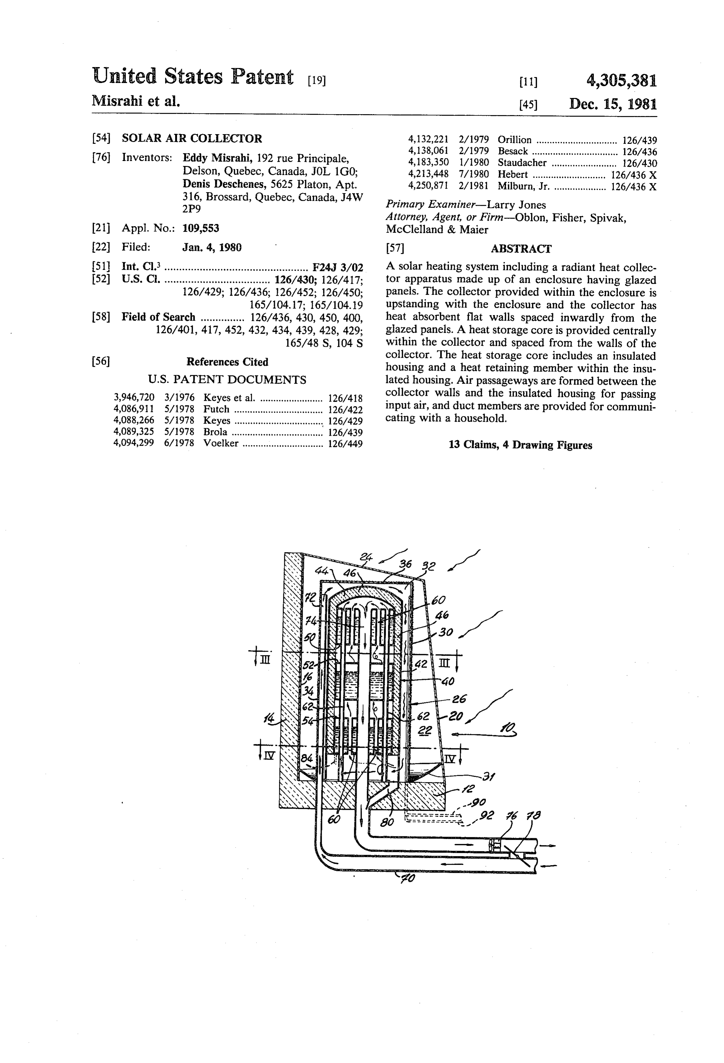
United States Patent (19) 11) 4,305,381 Misrahi et al. 45) Dec. 15, 1981 (54). SOLAR AIR COLLECTOR 4,132,221 2/1979 Orillion ............................... 126/439 4,138,061 2/1979 Besack...... ... 126/436 76 Inventors: Eddy Misrahi, 192 rue Principale, 4,183,350 1/1980 Staudacher ......................... 126/430 Delson, Quebec, Canada, JOL 1G0; 4,213,448 7/1980 Hebert .......... ... 126/436 X Denis Deschemes, 5625 Platon, Apt. 4,250,871 2/1981 Milburn, Jr... ... 126/436 X 316, Brossard, Quebec, Canada, J4W Primary Examiner-Larry Jones
Attorney, Agent, or Firm-Oblon, Fisher, Spivak, 21 Appl. No.: 109,553 McClelland & Maier 22 Filed: Jan. 4, 1980 57 ABSTRACT 51 Int. Cl.3 - -- - - - A solar heating system including a radiant heat collec 52 U.S.C. .................................... 126/430; 126/417; tor apparatus made up of an enclosure having glazed 126/429; 126/436; 126/452; 126/450; panels. The collector provided within the enclosure is 165/104.17; 165/104.19 upstanding with the enclosure and the collector has 58) Field of Search ............... 126/436, 430, 450, 400, heat absorbent flat walls spaced inwardly from the 126/401, 417,452, 432, 434, 439, 428,429; glazed panels. A heat storage core is provided centrally 165/48 S, 104 S within the collector and spaced from the walls of the 56 References Cited collector. The heat storage core includes an insulated housing and a heat retaining member within the insu
3,946,720 3/1976 Keyes et al. ........................ 126/48 collector walls and the insulated housing for passing 4,086,911 5/1978 Futch .................................. 126/422 input air, and duct members are provided for communi 4,088,266 5/1978 Keyes..... ... 126/429 cating with a household.
4,089,325 5/1978 Brola ...... 126/439 4,094,299 6/1978 Voelker ............................... 126/449 13 Claims, 4 Drawing Figures
Page 2
Drawing sheet — no readable text.
Page 3
Drawing sheet — no readable text.
Page 4
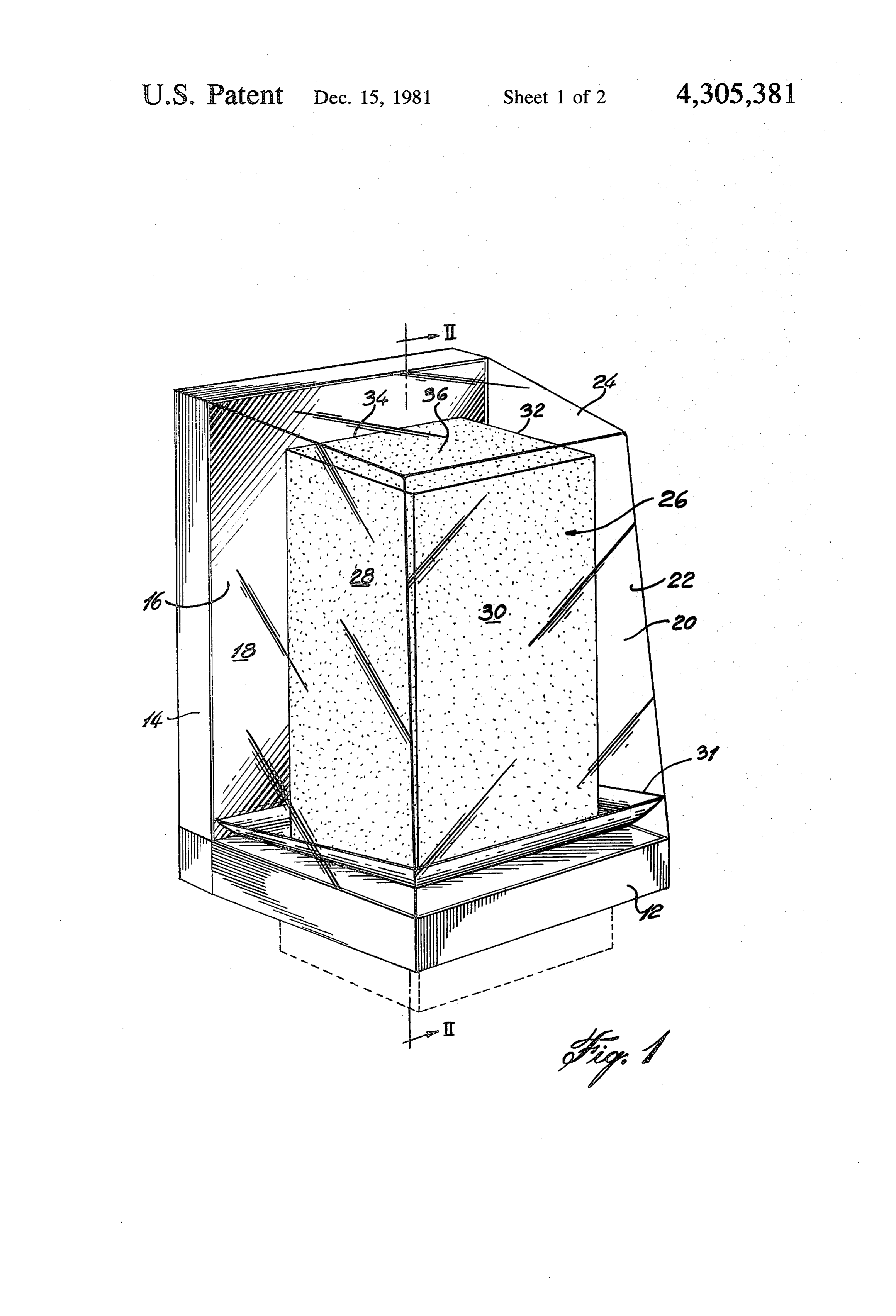
FIG. 1 is a perspective view of a typical solar con
SOLAR AIR COLLECTOR verting device;
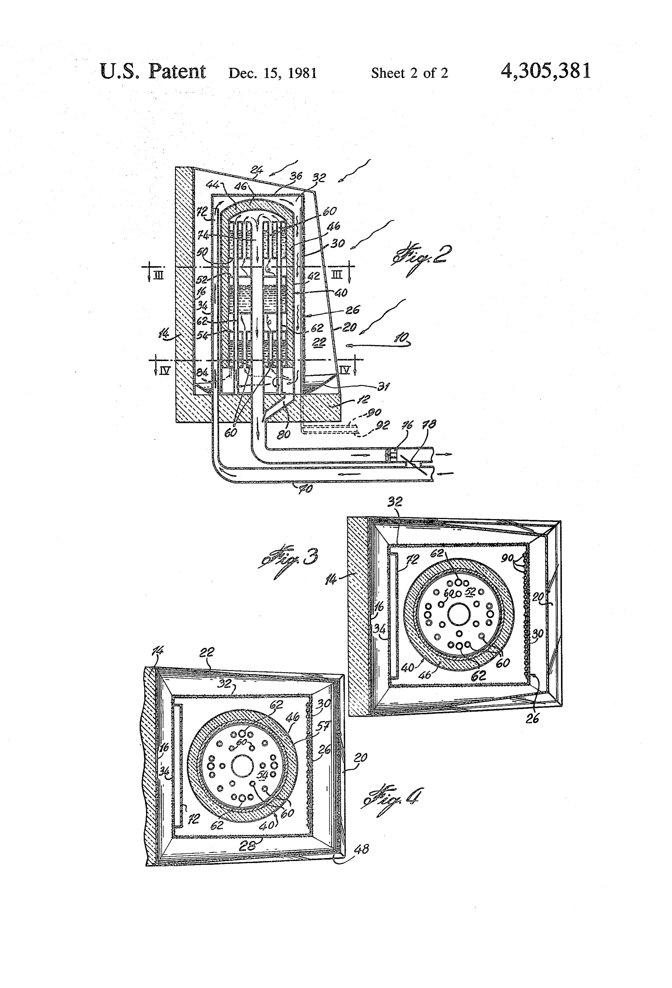
FIG. 2 is a vertical cross-section taken along line
BACKGROUND OF THE INVENTION II-II of FIG. 1;
1. Field of the Invention FIG. 3 is a horizontal cross-section taken along line The present invention relates to solar thermal energy III-III of FIG. 2; and collectors, and more particularly, to a collector which IV-IV FIG. 4 is a horizontal cross-section taken along line Of FIG. 2.
can be adapted for domestic use.
2. Description of the Prior Art O DETAILED DESCRIPTION OF THE Heretofore, many developments have been made in PREFERRED EMBODIMENTS the field of solar energy. To date, however, even con The embodiment illustrated in FIGS. 1 to 4 shows a sidering the fact that oil is expensive and that the source self-contained solar heating unit 10 which can be is in the hands of relatively few countries, there is yet no adapted to be mounted on a stand near a house and can practical collector which can be mass-produced for low 15 be placed in a rear yard of a house but near a wall price sale and installation at individual homes. thereof or can be placed on the roof of a flat-roof house. Most present day collectors are of the flat type which require expensive installation on rooftops, assuming the The unit has, as shown, a bottom wall 12 and a rear wall 14, the rear wall being at 90° to the bottom wall. A roof is properly oriented and at an angle. These flat reflective surface 16 can be provided on the rear wall collectors require considerable area with relatively low 20 14. The solar unit is constructed like a greenhouse, yield. The fact that they are laid out on the roof exposes including side-glazed panels 18, 20 and 22, as well as a them to the elements, and thus a fair amount of heat is top-glazed panel. The side glazed-panels 18, 20 and 22 lost on the roof before the heat is transferred by gas or are placed at a slight angle to the vertical so as to obtain liquid into the house. more direct exposure to the rays of the low winter sun. 25 Depending on the geographical location of the installa
SUMMARY OF THE INVENTION tion of the solar unit 10, the glazed walls or panels 18, 20 It is the object of the present invention to provide an and 22 would be at varying angles. Finally, a top-glazed upstanding, compact, self-contained solar collector and panel 24 is also provided, closing the greenhouse enclo heat storage unit adapted for household use which is sure of the unit 10. Each of the glazed panels 18, 20, 22 efficient and at the same time of low cost. 30 and 24 is flat and is hermetically sealed at its joints with Since the present invention has been made, applicant the other panels as well as with the floor and rear wall has been made aware of U.S. Pat. No. 4,138,061, Harold 12 and 4 respectively.
C. Besack, issued Feb. 6, 1979. This patent shows an Centrally within the enclosure there is provided a upstanding integral solar collector with a heat storage 35 heat collector 26 which includes four rectangular panels system, but with a portion of the unit below ground. It 28, 30, 32 and 34. A square panel 36 forms the top of the is not readily apparent how the Besack unit can operate heat enclosure unit 26. All of the panels are hermetically efficiently in a residential area where it can only project sealed to each other. Each of the panels may be formed a short distance above the level of the ground and not of a sheeting material which has been blackened, either be provided on a roof or on a stand to get the full benefit with carbon black or with a black paint. It has been of exposure to the sun. found that the provision of sand mixed in the solution, It is an aim of the present invention to provide an such yield as paint, covering the sheeting will give a better since the sand will cause the paint to be roughened improved solar collection unit which is more efficient and present myriad small surfaces to absorb solar en than present solar collection units.
A construction in accordance with the present inven 45 outer surfaces sun.
ergy from the
It is noted that both the inner and
tion includes a solar heating system including a radiant heat collector apparatus including an enclosure having with the mixture of sand and black paint. Reflective surfaces 31 are provided at the bottom glazed panels joined together, a collector provided within the enclosure and upstanding therewith, the between panels 30, the glazed panels 18, 20, 22 and 24 and the 32, 34 and 36. The reflective surfaces 31 are collector including heat absorbent flat walls spaced 50 set at an angle to reflect sunlight inwardly towards the inwardly from the glazed panels, a heat storage core walls of collector 26. The angles vary between 20 and provided centrally within the collector and spaced from 30 from the horizontal. Underneath the reflective sur the walls of the collector, the heat storage core includ faces 31, moisture absorbing pads may be provided. ing an insulated housing and a heat retaining member As shown in FIGS. 2 to 4, the interior of the collector within the insulated housing, air passageways formed 55 device is somewhat hollow and includes in the middle between the collector walls and the insulated housing thereof a cylindrical heat storage core 40 includes a for passing the input air, duct members communicating housing. The heat storage core 40 has an outer cylindri with a household or the like and the passageway, a cal wall 42 and a dome-shaped top wall 44. The walls member for passing air coming from the passageways of are provided with an insulating material 46 which will the solar collector through the heat storage core, and 60 retain the heat within the heat storage core 40. The output duct members for passing heated air from the outer surface of core 40 is covered with a smooth reflec heat storage core to the household or the like. tive surface 57, such as aluminum sheeting. The interior BRIEF DESCRIPTION OF THE DRAWINGS. of the insulating wall 42 is also provided with a similar sheeting. In the present instance, the heat storage core
Having thus generally described the nature of the 65 40 includes, within its hollowed-out portion, three core invention, reference will now be made to the accompa segments 50, 52 and 54. Each of these core segments is nying drawings, showing by way of illustration, a pre adapted to receive and communicate with a water sup ferred embodiment thereof, and in which: ply. A plurality of ducts 60 passes through each of the
Page 5
segments, and the inner surface of the ducts acts as a dissipated from the air to the storage segments. How heat transfer surface from the air having been heated, as ever, as soon as the air is cooled down to below the will be described, to heat the liquid, such as water, average temperature of the core segments 50, 52 and 54, within the segments 50, 52 and 54. The water can be the reverse will occur, that is, heat will be absorbed by drawn off and circulated to heat some other utility. the air as it passes through the ducts 60 and 62, that is, In a true heat balance system, however, water may be heat coming from the storage core. The embodiment replaced by wax or other known heat storage devices. shown in the drawings does not illustrate a heat storage In such a case, further heat transfer devices, such as core which can store heat for later use since the heat metalic screening, are provided within the segments storage core is relatively small. However, it is intended and connected to the ducts 60 and 62. 10 to utilize the heat storage core in a manner that will An input duct 70 communicates with the init E0 provide a relatively constant output temperature of the through the botton wall 2 and with a flat narrow duct air drawn through the system and the duct 74. 72 formed against the rear wall 34 of the collector unit It is recognized that the air space between the seg 26. Fresh air is drawn upwardly through the duct 72, ments 50, 52 and 54 is important since the volume of air picking up heat from the rear wall 34, to the top portion 5 in these spaces is relatively large such that the velocity of the collector device 26. The fresh air will thus pick of the air flow through the various ducts is much up heat from the top wall 36 which then passes down wardly along the three other walls 28, 30 and 32 of the greater other.
than the flow of air from one segment to the
Further, when the solar heating apparatus is not enclosure 26. The air so heated, that is, by passing being utilized, the through the duct 72, the top wall 36, and the side walls considerably by thecooling down of the core is delayed insulation effect of the air between 28, 30 and 32, is drawn upwardly through the ducts 60 the various segments. For instance, although segment and 62 of heat storage core segments 50, 52 and 54 up 54 may be the first to cool down, the air in the area into the dome 44 thereof, where the air is then drawn down through an exit duct 74. The exit duct includes a between segments 54 and 52 will insulate segment 52, fan 76 for drawing the air through the system and forc 25 thereby storage delaying the dissipation of the heat from the core segment 52 and so on up to the core seg ing it into the house. A diverting valve or baffle 78 can ment 50. Accordingly, it has been found that the heat be provided for shutting off the solar heating device, storage core does not completely cool down overnight, particularly at night time. When the valve 78 is closed, and thus when the system is put into operation in early the fan might still operate in order to recirculate the air morning, it can be preheated by the heat which is still in the system. This would be useful, for instance, in 30 summer when it is required to heat water for a hot retained in the upper segments in the core section 40. water system. A bypass 80 can also be utilized rather Small deflector plates or heat transfer fins can be pro than by passing the air through the ducting system 60, vided (not shown) on the segments 50, 52 and 54 and 62 and 74 so that the heated air can be sent directly extending within the air space between the segments. through the exit duct 74. 35 As previously indicated, the interior wall of the core is In operation, the cool air from a household is drawn provided with a continuous reflecting surface such as a through the inlet duct 70 up through the duct 72 against metal foil 55 so as to reflect the heat back into the air the rear wall 34 which will heat some of the air going up spaces of the core.
through the duct 72. The air is force fed by the drawing In the case where one wishes to bypass the storage power of fan 76 such that the cool air is, of course, . device so that hot air is immediately sent into the house moving upwardly in the duct 72 and will be drawn hold, then the bypass 80 can be utilized by closing the downwardly along the walls 28, 30 and 32 of the heat valve 81.
collector 26. The direction of air is counter-convection, In warmer temperatures, the storage segments 50, 52 as the air is absorbing more and more heat as it moves and 54 can be utilized for heating water for a hot water progressively within the system. These walls, of course, 45 system in the household. A pipe 84 is illustrated commu absorb considerable heat from the sun and thus the heat nicating with the segment 54 and is representative of is transferred along its inner surfaces to the air passing this alternative.
therealong. The heated air then enters the heat storage It is understood that this unit would probably not be core 40 through the bottom of the device and up sufficient for heating a household 24 hours a day, partic through the ducts 60 and 62. Some of the ducts 62 con 50 ularly in colder climates. However, the device can cer duct the air directly through the segments 50, 52 and 54 tainly be used as a supplement in the winter-time and to the exit duct 74, that is, at the top of the exit duct. also as described for the summertime for heating both Other ducts 60 allow for the air to meander about the hot water and for sending hot air into the household. segments and find its way upwardly through the seg Another manner of heating water would be to have hot ments until it reaches the top of the storage device and 55 water pipes 90 bringing cool water into the enclosure, is drawn downwardly through the exit duct 74 past the and the pipes could be strewn along the inner surface of fan 76. wall 30 as shown, and the return 92 would pass to the It is anticipated that as clouds pass and hide the sun, hot water system in the household.
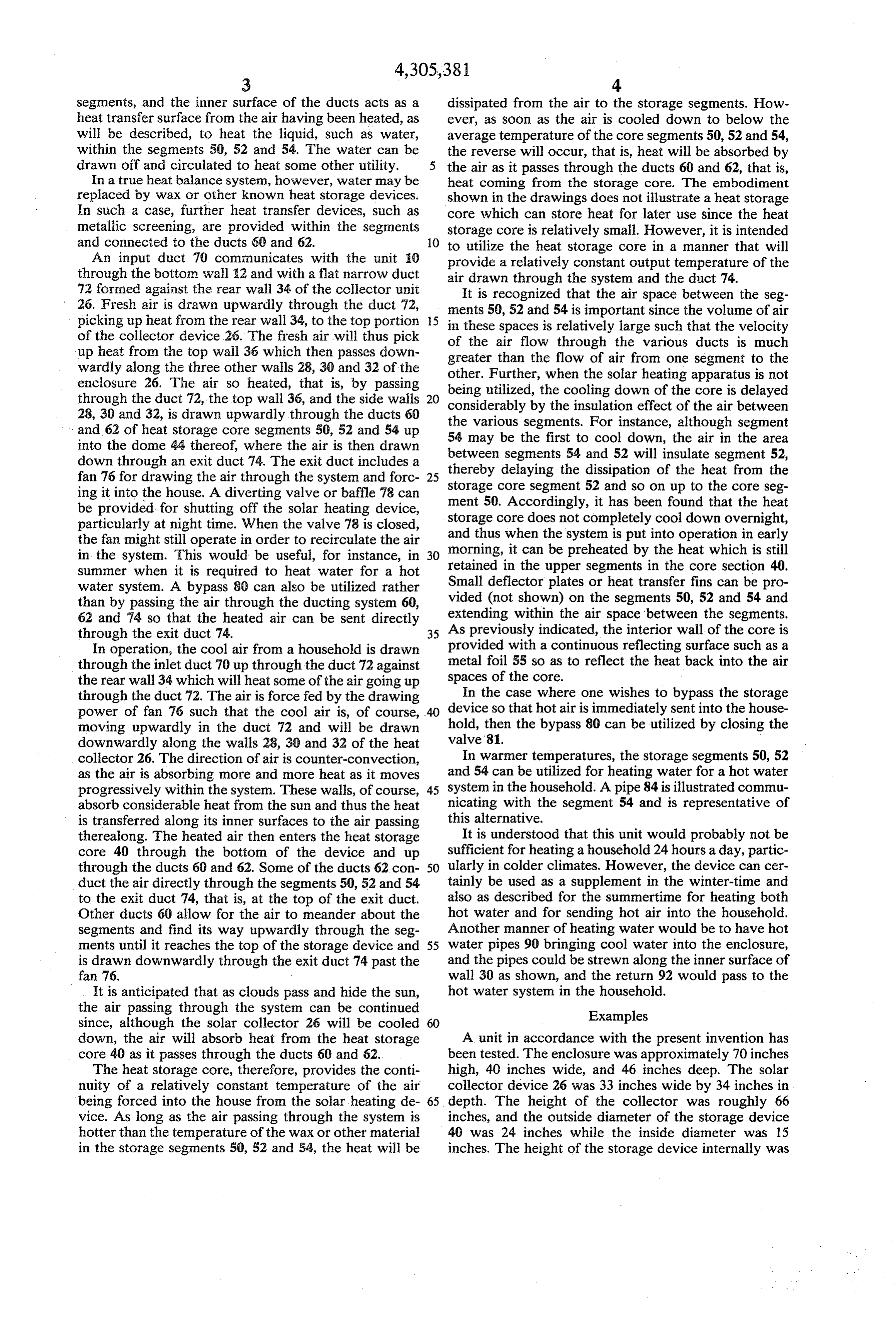
the air passing through the system can be continued Examples since, although the solar collector 26 will be cooled 60 down, the air will absorb heat from the heat storage A unit in accordance with the present invention has core 40 as it passes through the ducts 60 and 62. been tested. The enclosure was approximately 70 inches The heat storage core, therefore, provides the conti high, 40 inches wide, and 46 inches deep. The solar nuity of a relatively constant temperature of the air collector device 26 was 33 inches wide by 34 inches in being forced into the house from the solar heating de 65 depth. The height of the collector was roughly 66 vice. As long as the air passing through the system is inches, and the outside diameter of the storage device hotter than the temperature of the wax or other material 40 was 24 inches while the inside diameter was 15 in the storage segments 50, 52 and 54, the heat will be inches. The height of the storage device internally was
Page 6
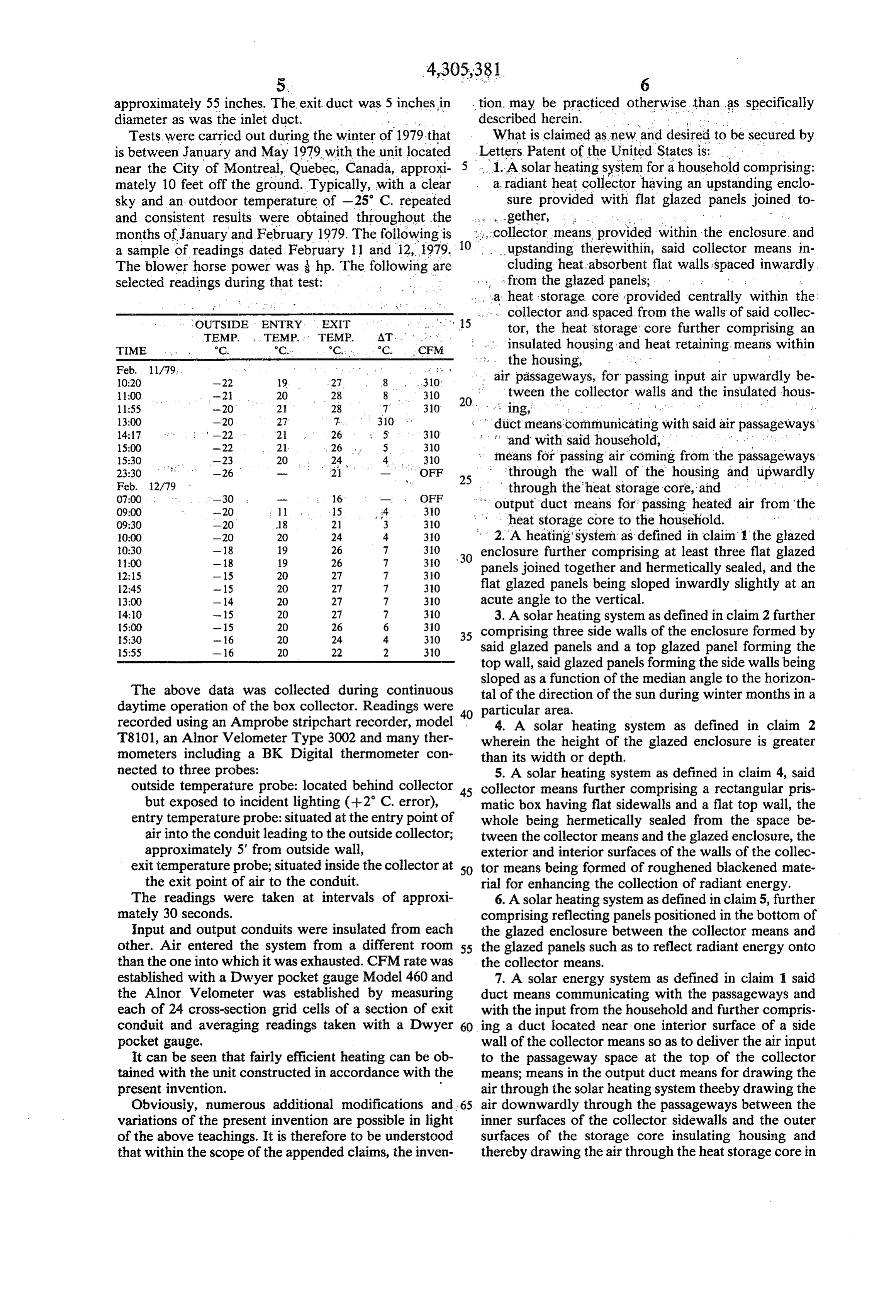
approximately 55 inches. The exit duct was 5 inches in stion may be practiced otherwise than as specifically diameter as was the inlet duct. . .. described herein. - . . . . . .. . . . . . ; Tests were carried out during the winter of 1979 that What is claimed as new and desired to be secured by is between January and May 1979 with the unit located 5 Letters Patent of the United States is: . . . near the City of Montreal, Quebec, Canada, approxi 1. A solar heating system for a household comprising: mately 10 feet off the ground. Typically, with a clear a radiant heat collector having an upstanding enclo sky and an outdoor temperature of -25 C. repeated sure provided with flat glazed panels joined to and consistent results were obtained throughout the ... ...gether, ... . . . . . months of January and February 1979. The following is collector means provided within the enclosure and a sample of readings dated February 11 and 12, 1979. 10. upstanding therewithin, said collector means in The blower horse power was hp. The following are cluding heat:absorbent flat walls spaced inwardly selected readings during that test: - s from the glazed panels;
a heat storage core provided centrally within the:
OUTSIDE ENTRY
: . . collector and spaced from the walls of said collec
TEMP. TEMP.
EXT
TEMP.
1s x. tor, the heat storage core further comprising an
TIME °C, °C. C. C. CFM insulated housing and heat retaining means within
Feb. 11/79. :
O:20 -22 19 27 8 310 air passageways, for passing input air upwardly be tween the collector walls and the insulated hous
310 20. ing, . . . . . . . . . . . .:
duct means communicating with said air passageways 15:00 -22 2 , 26 5. 310 and with said household, 15:30 -23 20 24 4, 310 : means for passing air coming from the passageways 23:30 -26 - OFF 25 - through the wall of the housing and upwardly
OFF through the heat storage core, and 09:00 -20 1 15 4 310 output duct means for passing heated air from the 09:30 -20 18 21 3 30 heat storage core to the household. O:00 -20 20 24 4. 30 2. A heating system as defined in claim 1 the glazed 30 enclosure further comprising at least three flat glazed 10:30 - 18 19 26 7 310 11:00 - 18 19 26 7 30 panels joined together and hermetically sealed, and the 12:15 - 15 20 27 7 310 12:45 - 15 2O 27 7 310 flat glazed panels being sloped inwardly slightly at an 13:00 - 4 20 27 7 30 acute angle to the vertical.
3. A solar heating system as defined in claim 2 further 5:30 -6 20 24 4. 310 35 comprising three side walls of the enclosure formed by 15:55 -16 20 22 2 310 said glazed panels and a top glazed panel forming the top wall, said glazed panels forming the side walls being sloped as a function of the median angle to the horizon
The above data was collected during continuous tal of the direction of the sun during winter months in a daytime operation of the box collector. Readings were 40 particular area.
recorded using an Amprobe stripchart recorder, model 4. A solar heating system as defined in claim 2 T8101, an Alnor Velometer Type 3002 and many ther wherein the height of the glazed enclosure is greater mometers including a BK Digital thermometer con than its width or depth.
nected to three probes: 5. A solar heating system as defined in claim 4, said outside temperature probe: located behind collector 45 collector means further comprising a rectangular pris but exposed to incident lighting (-2 C. error), matic box having flat sidewalls and a flat top wall, the entry temperature probe: situated at the entry point of whole being hermetically sealed from the space be air into the conduit leading to the outside collector; tween the collector means and the glazed enclosure, the approximately 5' from outside wall, exterior and interior surfaces of the walls of the collec exit temperature probe; situated inside the collector at 50 tor means being formed of roughened blackened mate the exit point of air to the conduit. rial for enhancing the collection of radiant energy, The readings were taken at intervals of approxi 6. A solar heating system as defined in claim 5, further mately 30 seconds. comprising reflecting panels positioned in the bottom of Input and output conduits were insulated from each the glazed enclosure between the collector means and other. Air entered the system from a different room 55 the glazed panels such as to reflect radiant energy onto than the one into which it was exhausted. CFM rate was the collector means.
established with a Dwyer pocket gauge Model 460 and 7. A solar energy system as defined in claim 1 said the Alnor Velometer was established by measuring duct means communicating with the passageways and each of 24 cross-section grid cells of a section of exit with the input from the household and further compris conduit and averaging readings taken with a Dwyer ing a duct located near one interior surface of a side pocket gauge. wall of the collector means so as to deliver the air input It can be seen that fairly efficient heating can be ob to the passageway space at the top of the collector tained with the unit constructed in accordance with the means; means in the output duct means for drawing the present invention. air through the solar heating system theeby drawing the Obviously, numerous additional modifications and 65 air downwardly through the passageways between the variations of the present invention are possible in light inner surfaces of the collector sidewalls and the outer of the above teachings. It is therefore to be understood surfaces of the storage core insulating housing and that within the scope of the appended claims, the inven thereby drawing the air through the heat storage core in
Page 7
an upward direction and finally through the output duct storage segments and communicating with an air ple means from the heat storage core. num at the top of the core. 8. A solar energy system as defined in claim 7, further 12. A solar heating system as defined in claim 7, fur comprising a reflector surface on the insulating housing ther comprising bypass means for bypassing the air from contacting said passageway between the housing and 5 the pasageways to the output duct without passing the inner surfaces of the walls forming the collector through the heat storage core.
eaS, 9. A solar heating system as defined in claim 7, said ant13.solar
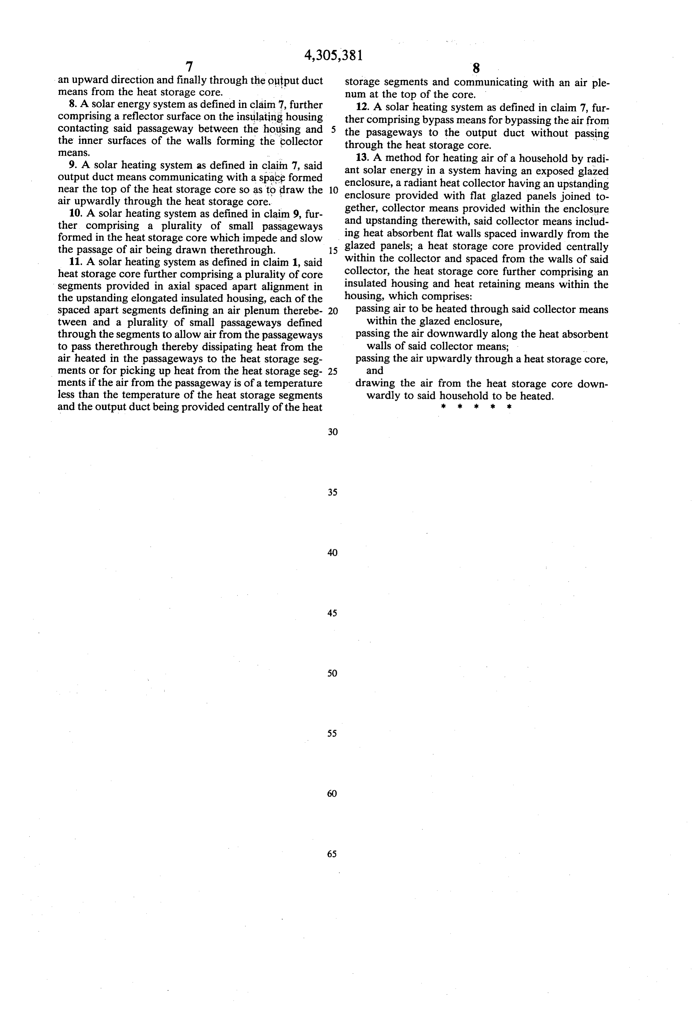
A method for heating air of a household by radi output duct means communicating with a space formed enclosure,energy in a system having an exposed glazed near the top of the heat storage core so as to draw the enclosure provided heat
with collector having an upstanding flat glazed panels joined to air upwardly through the heat storage core.
gether, collector means provided within the enclosure 10. A solar heating system as defined in claim 9, fur and upstanding therewith, said collector ther comprising a plurality of small passageways means includ formed in the heat storage core which impede and slow glazeding heat absorbent flat walls spaced inwardly from the the passage of air being drawn therethrough. 15 panels; a heat storage core provided centrally 11. A solar heating system as defined in claim 1, said within the collector and spaced from the walls of said heat storage core further comprising a plurality of core collector, the heat storage core further comprising an segments provided in axial spaced apart alignment in insulated housing and heat retaining means within the the upstanding elongated insulated housing, each of the housing, which comprises:
spaced apart segments defining an air plenum therebe- 20 passing air to be heated through said collector means tween and a plurality of small passageways defined within the glazed enclosure, through the segments to allow air from the passageways passing the air downwardly along the heat absorbent to pass therethrough thereby dissipating heat from the walls of said collector means; air heated in the passageways to the heat storage seg passing the air upwardly through a heat storage core, ments or for picking up heat from the heat storage seg- 25 and ments if the air from the passageway is of a temperature drawing the air from the heat storage core down less than the temperature of the heat storage segments wardly to said household to be heated. and the output duct being provided centrally of the heat k sk sk k
Provenance
- Collection
- Cited prior art
- Original PDF
- patentimages.storage.googleapis.com →
- Filed
- 1980-01-04
- Pages
- 7
- Method
- pdftotext (the PDF's own text layer) + pdftoppm 300dpi page scans
- Source
- Google Patents bibliographic record
- Granted
- 1981-12-15
- Inventors
- Eddy Misrahi; Denis Deschenes
- Transcribed from
- patentimages.storage.googleapis.com →