patent · US6132204
Wide flame burner
17 October 2000
Page 1 — bibliographic record
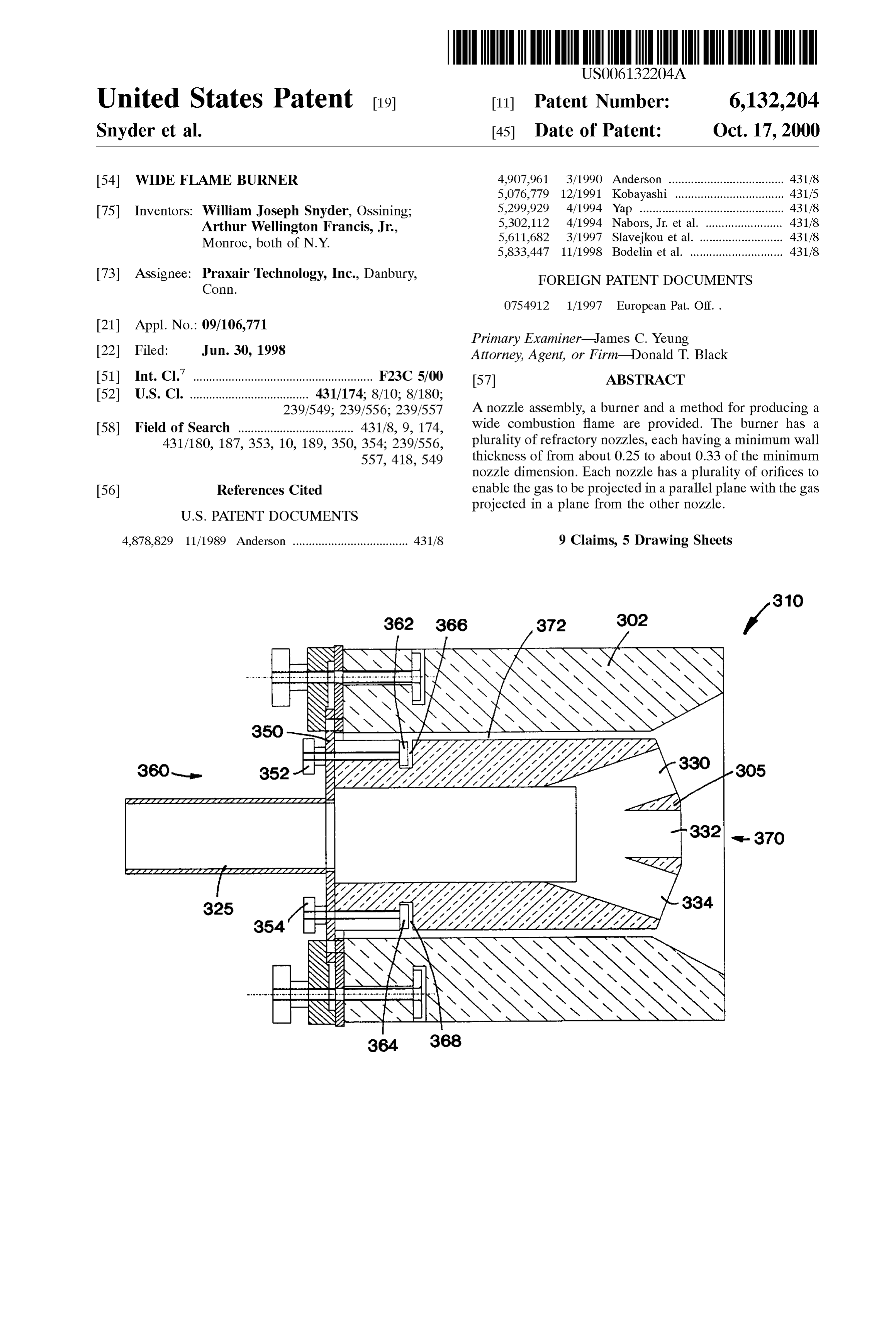
United States Patent (19) 11 Patent Number: 6,132,204 Snyder et al. (45) Date of Patent: Oct. 17, 2000 54) WIDE FLAME BURNER 4,907,961 3/1990 Anderson .................................... 431/8 5,076,779 12/1991 Kobayashi .................................. 431/5 (75) Inventors: William Joseph Snyder, OSSining; 5,299,929 4/1994 Yap ---- --- ---------- --- --- ------- --- --- --------- 431/8
Arthur Wellington Francis, Jr., 5,302,112 4/1994 Nabors, Jr. et al. ........................ 431/8 5,611,682 3/1997 Slavejkou et al. .......................... 431/8
Monroe, both of N.Y. 5,833,447 11/1998 Bodelin et al. ............................. 431/8 73 ASSignee: Prair Technology, Inc., Danbury, FOREIGN PATENT DOCUMENTS
Primary Examiner James C. Yeung 22Filed: Jun. 30, 1998 Attorney, Agent, or Firm Donald T. Black
Int. Cl. .................................................. F23C 5700 57 ABSTRACT 52U.S. Cl. ..................................... 431/174; 8/10; 8/180;
239/549; 239/556; 239/557 A nozzle assembly, a burner and a method for producing a 58 Field of Search .................................... 431/8, 9, 174, wide combustion flame are provided. The burner has a 431/180, 187, 353, 10, 189, 350, 354; 239/556, plurality of refractory nozzles, each having a minimum wall 557, 418,549 thickness of from about 0.25 to about 0.33 of the minimum nozzle dimension. Each nozzle has a plurality of orifices to 56) References Cited enable the gas to be projected in a parallel plane with the gas projected in a plane from the other nozzle.
4,878,829 11/1989 Anderson .................................... 431/8 9 Claims, 5 Drawing Sheets
Page 2
Drawing sheet — no readable text.
Page 3
Drawing sheet — no readable text.
Page 4
Drawing sheet — no readable text.
Page 5
Drawing sheet — no readable text.
Page 6
Drawing sheet — no readable text.
Page 7
WIDE FLAME BURNER In an alternative embodiment, this invention is also
FIELD OF THE INVENTION
directed to a nozzle assembly for Separate injection of a wide oxidant layer and a wide fuel layer into a combustion Zone
This invention relates to a method and System for com comprising (a) a first refractory nozzle having a minimum busting materials, and more particularly for carrying out wall thickness of from about 0.25 to about 0.33 of the combustion with a wide flame. minimum nozzle dimension, the nozzle comprising a plu
BACKGROUND OF THE INVENTION
rality of first orifices, the first orifices defining a first plane;
(b) a second refractory nozzle having a minimum wall
A need had arisen in the Oxy-fuel firing of glass furnaces thickness of from about 0.25 to about 0.33 of the minimum to achieve greater coverage of the glass Surface with a flame. nozzle dimension, the nozzle comprising a plurality of One way of accomplishing this is to use a wide flame burner. Second orifices, the Second orifices defining a Second plane This type of burner produces a flame in which the dimension that is parallel to the first plane; (c) a first conduit means in through the horizontal axis is much greater than through the fluid communication with each of the first orifices for Vertical axis at any cross-section along the axis of the flame. passing oxidant from an oxidant Source to the first orifices, Recently, other manufacturers have been Successfully 15 and (d) a Second conduit means in fluid communication with marketing the advantages of using wide flame burners in each of the Second orifices for passing fuel from a fuel glass furnaces. However, commercialization of these burn orificesSource to the Second orifices, wherein each of the first erS has been problematical. Burner overheating, block orifice. is vertically aligned with a corresponding Second erosion, nozzle plugging and poor flame shapes all had to be addressed. To overcome these problems with a simpler In yet another alternative embodiment, this invention is burner geometry, an effort was undertaken to find a better directed to a burner for producing a wide combustion flame way of producing a flat flame from an Oxy-fuel burner. comprising (a) a first refractory nozzle having a minimum Several wide flame burners are available on the market wall thickness of from about 0.25 to about 0.33 of the and each uses various different techniques to generate minimum nozzle dimension and comprising a plurality of flames. EP 754,912 A2 discloses the injection of converging 25 first orifices; (b) a second refractory nozzle having a mini mum wall thickness of from about 0.25 to about 0.33 of the fuel and oxygen Streams at low velocities to produce a long wide flame from a burner. minimum nozzle dimension and comprising a plurality of U.S. Pat. No. 5,299,929 discloses a burner where multiple Second orifices, the number of first orifices being the same as the number of Second orifices; (c) a refractory material fuel orifices in a fan shaped pattern are used to distribute the placed between each of the first and Second refractory fuel in a wide fan-shaped flame. This fuel is sandwiched between two closely spaced oxygen passages above and nozzle; (d) the first and Second nozzle removably mounted below with baffles that force the oxygen to follow a fan on a refractory burner block such that each of the first orifices is vertically aligned with a corresponding Second shaped path as it exits the burner.
U.S. Pat. No. 5,302,112 discloses a burner where a stream orifices; (e) a first conduit means in fluid communication of low velocity fuel and oxygen are purposely collided 35 with each of the first orifices for passing oxidant from an together along a vertical axis. When adjusted correctly, this means inSource oxidant to the first orifices; and (f) a second conduit fluid communication with each of the Second produces a horizontal flat flame initiating at the point of orifices for passing fuel from a fuel Source to the Second collision in the furnace.
orifices wherein each of the Second orifices is vertically
U.S. Pat. No. 5,611,682 discloses the use of an elongated aligned and at the same angle with a corresponding first opening to produce a wide or fan Shaped flame for the burner 40 orifice.
described.
Various issues involving operation and maintenance prob theThe first refractory nozzle may be located above or below second refractory nozzle. The number of orifices in the lems are not adequately addressed in the art Such as the first nozzle is preferably the same as the number of orifices capacity to operate for a prolonged period at high tempera in the Second nozzle. The oxidant is a fluid having an oxygen ture and the avoidance of nozzle clogs, block erosion and 45 concentration of at least 30 percent by volume. Preferably, poor flame shape. Accordingly, there is a need to Solve these pure oxygen is used as an oxidant. The fuel preferably problems in the industry. comprises a gaseous fuel, including natural gas, and other SUMMARY OF THE INVENTION combustible gases known in the art Such as hydrogen, This invention is directed to a method for carrying out 50 propane and liquified petroleum gas.
combustion with a wide flame comprising the Steps of (a) preheated Either the oxidant and/or the fuel may be externally providing a combustion Zone containing an atmosphere of prior to injecting into the combustion Zone. furnace gases at a temperature exceeding about 1000 F.; (b) The first and second refractory nozzle of the assembly injecting a wide oxidant layer through a first refractory have a minimum wall thickness of less than 1.5" and each of nozzle having a plurality of first orifices at a Velocity of leSS 55 the orifices diverges with an adjacent orifice in the nozzle at than about 180 ft/sec to produce an oxidant layer in the an angle between 0 and 45 degrees. Each of the nozzles is combustion Zone; (c) injecting a wide fuel layer through a a replaceable unit and may be parallel to one another. Each Second refractory nozzle having a plurality of Second refractory nozzle may be recessed by the Same distance with orifices, the fuel being injected at a Velocity of less than respect to the burner block. Preferably, a refractory material about 210 ft/sec to produce a fuel layer in a plane parallel to 60 is placed between the first and Second refractory nozzle to the oxidant layer in the combustion Zone; (d) turbulently prevent any unexpected mixing of the oxidant and fuel in the mixing at least a portion of the Oxidant from the oxidant burner block.
layer with at least a portion of the fuel from the fuel layer to AS used herein, the term “combustible Zone” means a produce an oxidant-fuel mixture in a mixture layer within Volume in which fuel and oxidant mix and react to release the combustion Zone; and (e) combusting fuel and oxidant 65 heat.
within the mixture layer in the combustion Zone to produce AS used herein, the term "pure oxygen' means a gas a wide flame. having an oxygen concentration of at least 99.5 percent.
Page 8
AS used herein, the term "gaseous fuel” means a fuel temperatures produced when oxidant and fuel mix and burn, composed of one or more gaseous components, Some of the two reactant Streams are injected Separately through two which are combustible, liquid fuel droplets dispersed in a Similar nozzles and mix within the furnace once they are gaseous medium; Solid fuel particles dispersed in a gaseous Some distance from the nozzles. medium. By injecting the gases Separately, as Stated above, the AS used herein, the term “wide' in the context of wide NOX generated by this burner is about half that generated by flame means the flame exhibits an aspect ratio greater than any burner where all the oxidant and fuel are in direct 2 (i.e. the width of the flame's major axis is two or more contact within or immediately infront of a burner block. The times longer than the height of the flames minor axis) at any Vertical Spacing between the nozzles will influence flame croSS-Section along the axis of the flame. length and NOx levels and can be chosen ahead of time by design.
As used herein, the term “refractory” in the context of To avoid operating and maintenance problems, a simple “refractory block” means any of a series of materials which mechanical design of the burner is proposed. The Simplicity can withstand temperatures greater than 220 F. (1204 C.) also makes the burner a low cost item should it need and which usually comprise of oxides, nitrides or carbides of replacement. The velocities for the burner are kept low other metallic elements. Examples are Silica, fused silica, 15 (between 50 and 210 ft/sec) to minimize entrainment of bonded alumina-Zirconia-Silica, alumina, mullite, Silicon carbide, Silicon nitride and boron nitride. For the purpose of The orifices incondensable corrosive and furnace gases against the nozzle.
this invention, the preferred refractory material is an enable the nozzle to operateare the nozzle also kept relatively large to alumina-Zirconia-Silica refractory containing about 66% condensation of Volatiles in atthea high temperature and avoid atmosphere that could clog alumina, 21% zirconia and 12% silica. the nozzle. By using refractories for critical burner parts, the BRIEF DESCRIPTION OF THE DRAWINGS burner is also amenable to use with preheated feedstockS Such as preheated oxygen and preheated natural gas.
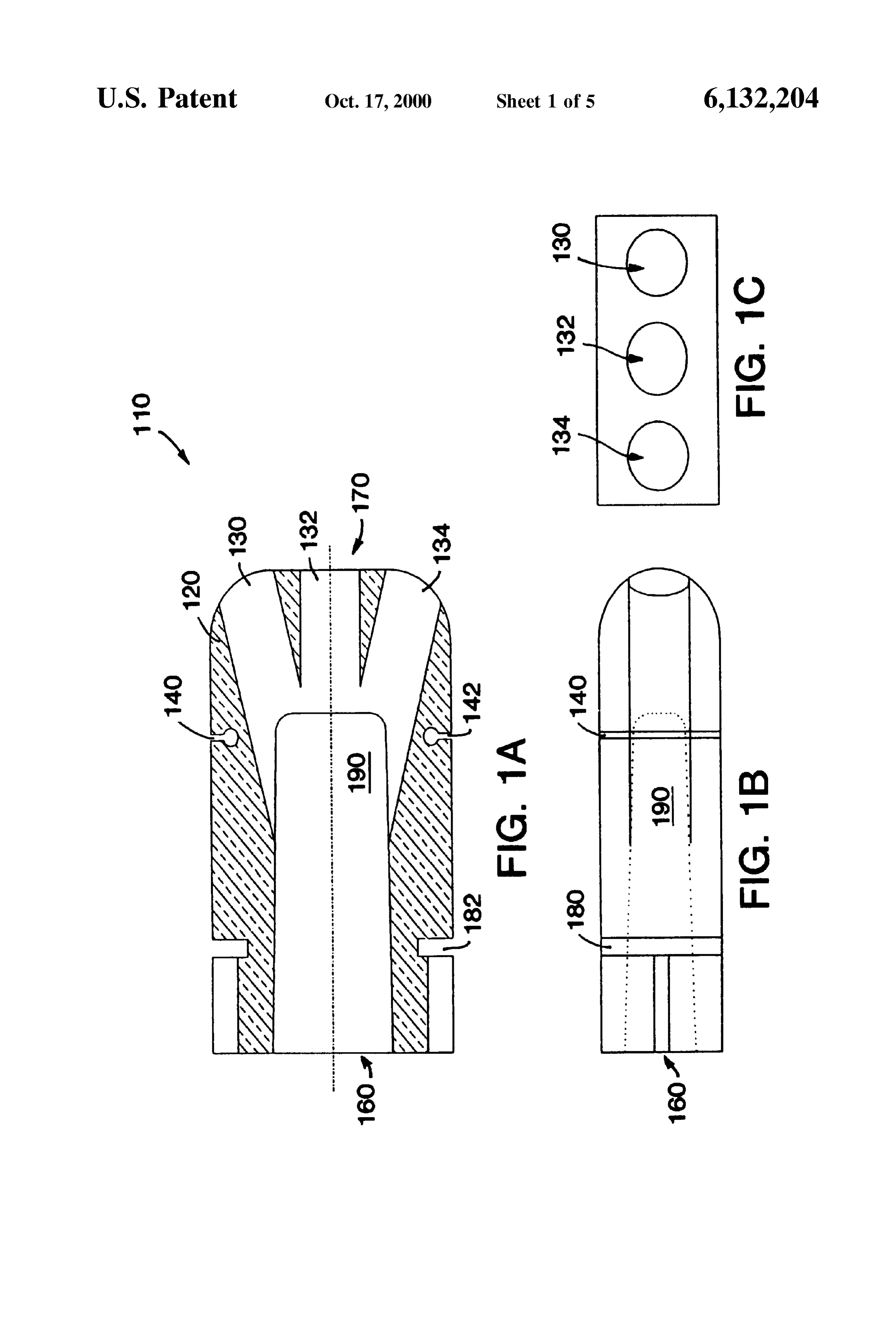
FIG. 1a is a top plan view of one embodiment of the This invention will be described in detail with reference nozzle of this invention. 25 to the drawings.
FIG. 1b is a side elevation view of the nozzle illustrated Mechanical Design in FIG. 1a. FIGS. 1a, 1b and 1c are sketches of the refractory nozzle. FIG. 1c is a head-on view of the nozzle illustrated in FIG. This is the heart of the invention in its simplicity and 1a. functionality. The nozzle 110 consists of a refractory brick FIG. 2a is a top plan view of a burner of this invention front 120 with three orifices 130, 132 and 134 drilled or cast in the having both a nozzle for the oxidant and the fuel. face 170 to allow gas to pass into the furnace. These FIG.2b is a head-on view of the burner illustrated in FIG. three orifices pass into a central larger passage 190 which 2a from the gas inlet end. brings the gas from the inlet end (back face) 160 of the burner to the outlet end (front face) 170 of the burner. The
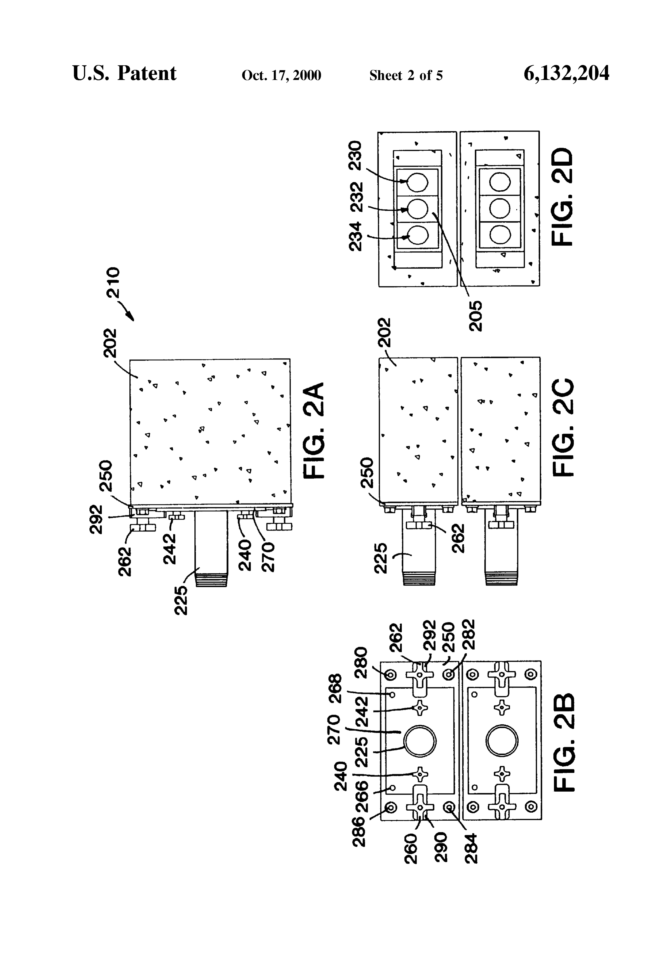
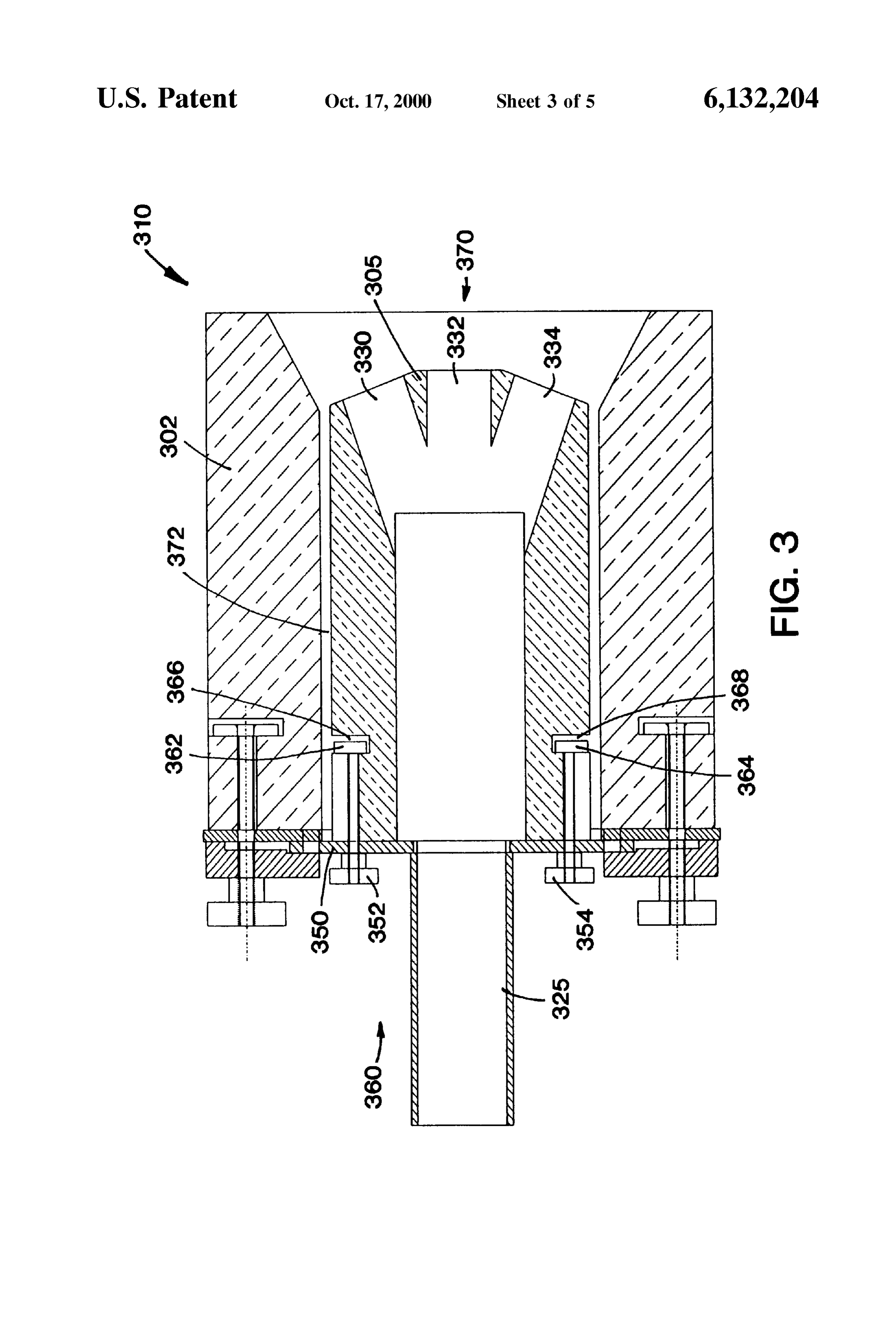
FIG.2c is a side elevation view of the burners illustrated 35 croSS-Sectional area of this passage is greater than 85% of in FIG. 2a. the area of the exit orifices in the face of the nozzle to insure FIG. 2d is a head-on view of the burner illustrated in FIG. a uniform distribution of gas to all the orifices. Two slots 180 2a from the gas outlet end. and 182 are cut or cast in each side of the brick to allow FIG. 3 is a cut away view of the burner through the nozzle mechanical fasteners to attach brick 120 to a metal mounting encompassing an alternative embodiment of the nozzle of 40 plate. Tapered plenum 190 is the conduit which distributes FIG. 1. the fuel or oxidant to orifices 130, 132 and 134. Stress slits 140 and 142 are provided in refractory brick 120 to aid in
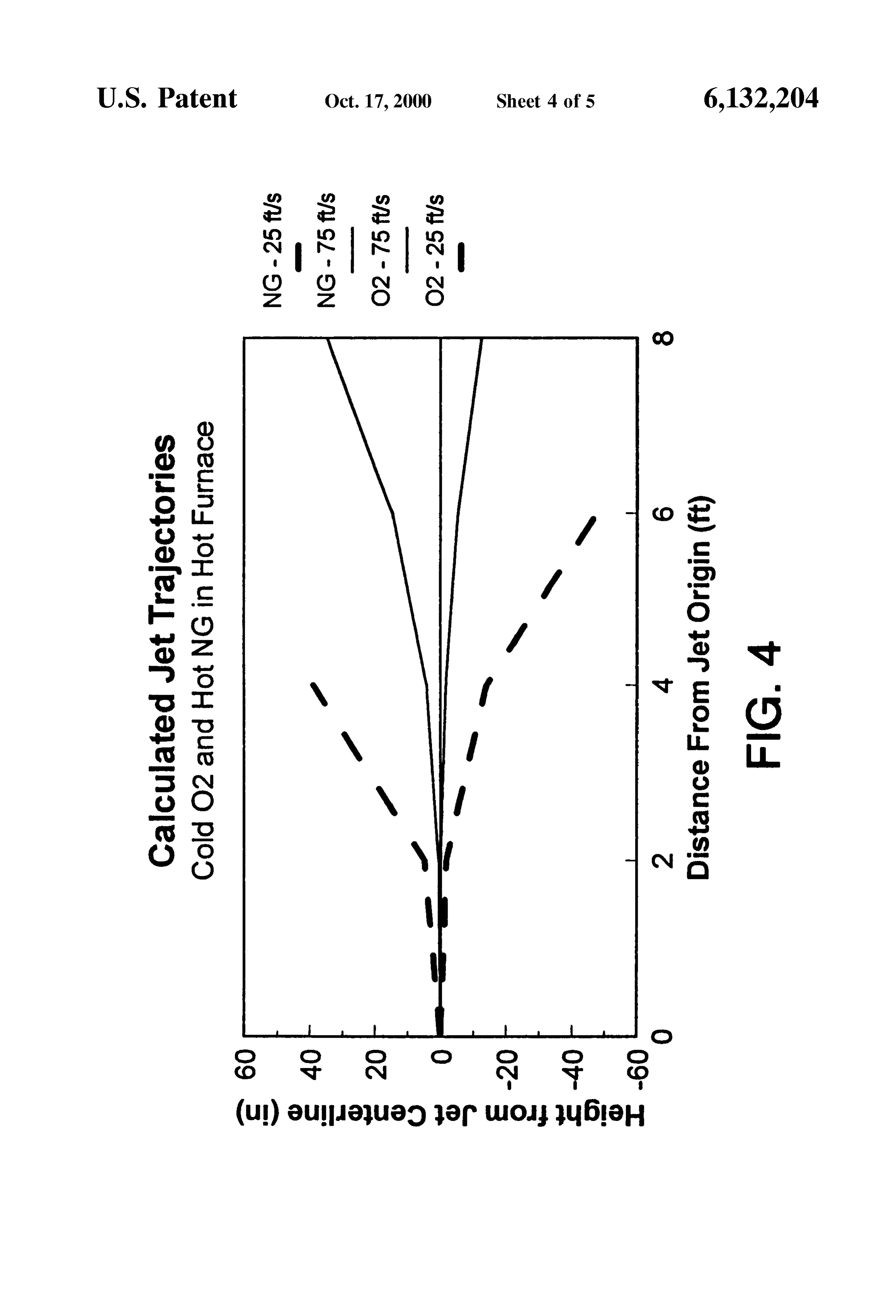
FIG. 4 is a plot of the calculated jet trajectories of the relieving height from the jet centerline (in.) as a function of the temperature the tensile StreSS produced as a result of the varying distance from the jet origin (ft.) for the burner of this 45 In FIG. 1c,inwhere the nozzle.
the horizontal length of the burner face invention.
along the three orifices
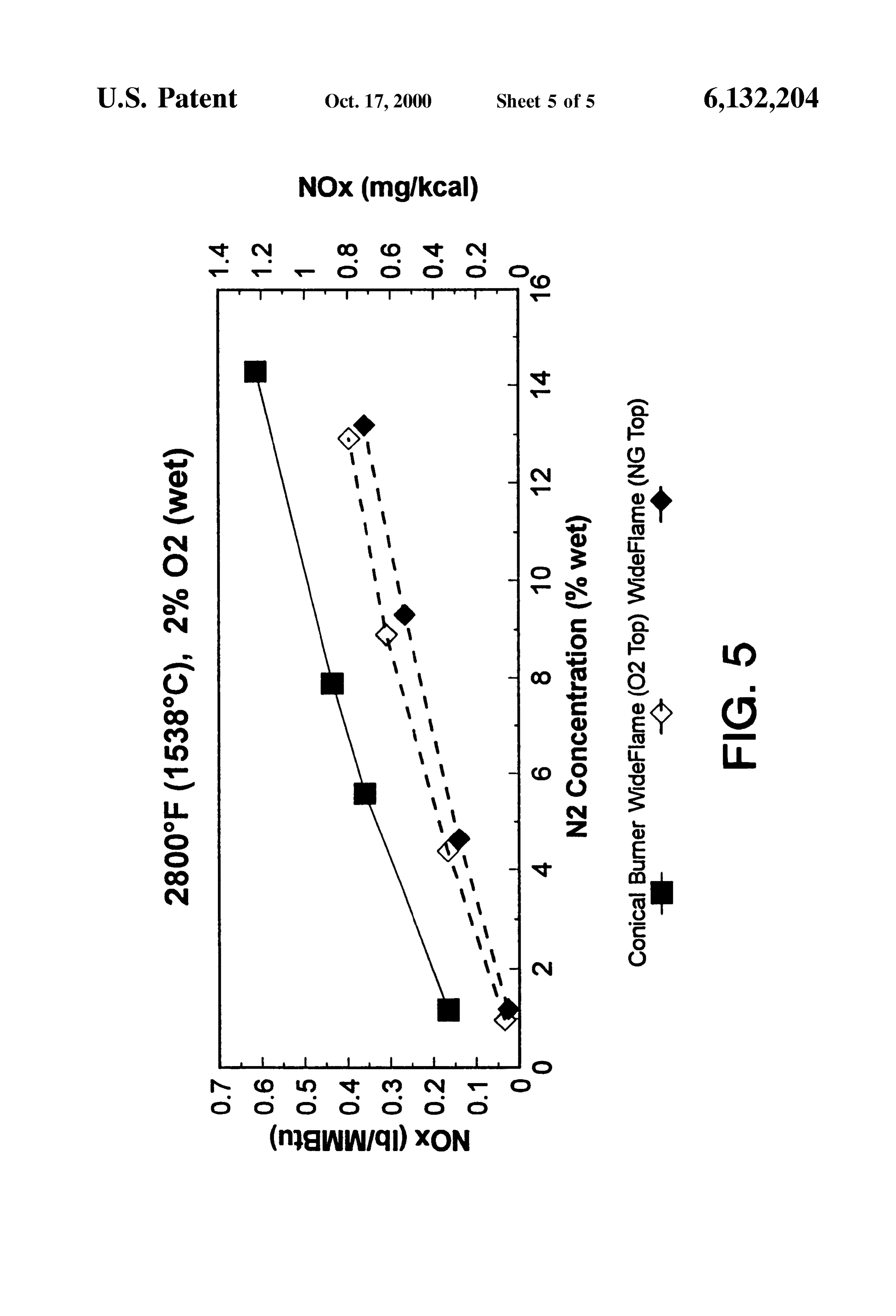
FIG. 5 is a plot of the relationship of the NOx emission Vertical length of the burner may be designated as "L' and the face passing through one orifice (1bm/MMBtu) as a function of the furnace N level (% wet) may be designated as “H”, the minimum nozzle dimension for the burner of this invention and a Standard burner design. is the length of H provided H is less than L. DETAILED DESCRIPTION 50 FIGS. 2a, 2b, 2c and 2d show the total burner configu ration which consists of two separate burner blocks for the
To produce a wide flame in this invention, multiple two nozzles comprising one burner. For Simplicity, only one conical fuel and oxidant jets are issued from two Separate will be described (shown in FIG. 2d as nozzle 205, termi nozzles in a fan shaped pattern. This allows fairly precise nating in orifices 230, 232 and 234) as both blocks are control over the distribution of fuel throughout the flame and 55 Similar in design. The Separated blockS facilitate adjusting its overall shape (i.e. width). The nozzle is located close to the vertical Spacing of the nozzles. In an alternative the inside (hot) Surface of the furnace wall So that the angle embodiment, it should be noted that one unified block of the fuel and oxidant jets can be manipulated to any comprising the two nozzles, each having a plurality of desired angle without being restricted by the confines of a orifices, is also contemplated.
narrow burner block. 60 The burner block 202 has a plate 250 mounted to the back Because of the high temperatures at this location in the of it to fasten the nozzles to and provide a Sealing Surface furnace, the burner nozzles are preferably made from a between the nozzle plate 270 and the burner block plate 250. refractory material. This eliminates the need for water This prevents cold air from leaking into the furnace around cooling and allows no metal parts to be placed near the hot the nozzle and hot furnace gases from leaking out. To Secure Surface of the furnace wall. The nozzle must be fairly rugged 65 the burner block plate 250 to the burner block 202, bolt to handle the potential for thermal and mechanical Shock and means 280,282,284 and 286 are used. The nozzle plate 270 hence has a fairly thick cross-section. To avoid excessive has two small alignment holes 266 and 268 in the top edge
Page 9
S 6 through which two pins on the burner block plate 250 pass, Typically, the wall thickness is 0.25 of the minimum nozzle so that the nozzle plate 270 can be accurately aligned with dimension (i.e. for a 3"x6" nozzle, the minimum wall the burner block plate 250. This positions the nozzle 205 in thickness will be 0.25*3"=0.75") or 1.5", whichever is less. burner 210 in the center of the opening in the burner block. To maximize the wall thickness around the main cavity The two small hand knobs 240 and 242 on either side of the down the center of the nozzle, an oval shaped hole is inlet pipe 225 fasten the nozzle plate 270 to the refractory provided in the nozzle's rectangular cross-section. These nozzle 205. In this way, a defective, worn or broken nozzle heavier Sections will be better able to resist cracking than can be exchanged and replaced with a new one and Still thin walled sections, and will be better able to resist nozzle utilize the same metallic components. The nozzle plate 270 rupture should cracks develop.
is fastened to burner block plate 250 via two larger hand The poor tensile Strength of the refractory material is knobs 260 and 262 and two swivel clamps 290 and 292. This addressed by designing the nozzle Such that all parts of the allows the nozzle 205 to be inserted and removed without having to remove any fastening devices from the burner nozzle experiencing tensile Stresses are in the colder regions block plate 250. This makes maintaining and servicing the of the burner and by limiting the internal pressure of the gas burner fairly easy and Straight forward. (by using low velocities) So as not to exacerbate the stress A top cut-away view of the burner 310 is shown in FIG. 15 condition in the nozzle. As noted in FIG. 1, stress slits 140 3. The nozzle 305 is centered in the opening of the burner and 142 are provided on the sides of the refractory brick block 302 and is shown recessed from the front end 370 of toward the front face. These slits aid to relieve the stress as the burner block. The nozzle shown is an alternative a result of the varying temperature in the nozzle. embodiment of the nozzle shown in FIG. 1 in that the front The machining issue is overcome by utilizing fairly face of the nozzle has two mitered cuts which are perpen Simple shapes which can be directly cast to their final shape, dicular to the drilled orifices 334 and 330, rather than a or partially cast to an intermediate shape and then, using rounded end. The openings at the front of the burner block Simple drilling techniques, customized for its particular 302 are tapered to avoid the angled jets of the nozzle from function.
impinging on the edges of the block. Because refractory has a low thermal conductivity, when The orifices 330,332 and 334 in nozzle 305 can be drilled 25 fuel and oxidant meet at its Surface and burn, a very high at any diameter and angle from the nozzle axis to vary the temperature region results because the refractory cannot wide flame characteristics emanating from the burner. transfer the heat of reaction away from the Surface quickly The nozzle 305 is secured to the nozzle mounting plate enough. To avoid this potential Overheating problem, the 350 via two T-bolts 362,364, which are inserted into slots fuel and oxidant are injected Separately through two nozzles 366, 368 on the rear end 360 of the nozzle 305. Two hand So there is little to no reaction at the Surface of the nozzle to knobs 352, 354 are used to fasten these two parts together. create overheating. All the combustion occurs in the furnace A gasket (not shown) is placed between the nozzle 305 and thereby allowing the refractory nozzle to remain at reason the nozzle mounting plate 350 to prevent gas from leaking able temperatures. In the event of nozzle failure (i.e. cracks, at this joint. A gap 372 is provided between the nozzle and breakage, etc.) the fuel or oxidant will flow out of the nozzle burner block So that in the event of a gas leak, the gas would 35 and be contained by the burner block to produce a poorly be directed harmlessly to the front of the burner block 370. defined flame without damaging or overheating the burner Inlet piping from a fuel or oxidant Supply can be connected block or nozzles.
to the inlet connection 325 as in any Standard plumbing To prevent the nozzle from becoming “glued' into the fashion. burner block because of frozen glass, Some design features Several advantages are realized by using refractory for 40 were included. First, the nozzle is recessed in the burner primary burner parts. First, the burner can remain in the block by about one inch and the burner block is recessed in furnace through any down period with no additional cooling the furnace wall by about one inch. This prevents any requirements. Typically, metallic burners must be removed rundown on the inside wall of the furnace from filling the or air cooled when the gas and oxidant flows to them are gap between the nozzle and the burner block and gluing the shutoff to avoid damaging/overheating the metal burner 45 two pieces together. To avoid condensables from collecting parts. Secondly, the higher Surface temperatures of the in colder regions of the burner, a 0.25" gap is provided burner components will prevent condensation of volatiles between the block and the nozzle. This is large enough to from the combustion atmosphere, which is a major problem prevent bridging of any condensables between the two in glass making furnaces causing plugging of orifices and surfaces. The low velocities employed with this burner frequent maintenance. Thirdly, refractory burner parts are 50 minimize furnace gases from being recirculated near the compatible with preheated fuel and/or oxidant Supplies in nozzle and contributing to corrosion or condensation. that no overheating of already thermally Stressed metallic Process Design parts will occur. Lastly, without nozzle temperature Flames for use in glass furnaces need the following concerns, the tip of the burner can be closer to the inside of attributes to be acceptable to the user: high luminosity, low the furnace thereby increasing the flexibility of the burner by 55 momentum, high aspect ratio (width of flame versus height allowing a variety of different nozzle drilling patterns to be of flame), no lofting (upward bending of flame due to employed. Each different pattern could result in a different buoyancy), Stability, no Smoke generation, low NOx and flame shape and heat delivery profile for the burner. This is carbon monoxide emissions. To achieve many of these not practical with metallic burners because they usually attributes, lower Velocity burner Systems are employed. require a deep, narrow burner block to protect the burner 60 Lower velocity jets behave differently than higher velocity from the radiant heat of the furnace So there is little jets because buoyancy becomes a larger component of the flexibility available for gas flow direction. Refractory burner force balance on the free jet System, and the larger diameter components do have a disadvantage in that they are Suscep holes prevalent in low velocity Systems delay jet mixing. tible to thermal shock, poor tensile Strength, and difficulty to The use of multiple jets also allows more flexibility in flame machine. 65 Shaping from a single burner.
To overcome the thermal shock problems, heavy walled The horizontal placement of the jets provides one param nozzles of thermally Shock resistant materials are used. eter which can be manipulated to create different jet and
Page 10
hence flame effects in the furnace. The turbulent nature of a To produce luminous flames and avoid nozzle plugging/ gas jet injected into a medium creates entrainment of Sur corrosion issues, a preselected Velocity is used to create a rounding fluid into the jets and results in the expansion of the different combustion process. A turndown test revealed that jet and a dissipation of its Velocity. A jet will entrain gases the burner could be operated between 70 and 210 ft/sec for from all SideS as it expands and if Sufficient gas is not the natural gas Stream and 50 and 180 ft/sec for the oxygen available, it will recirculate its own gases from a point Stream while Still maintaining a productive flame. At the low further downstream back to the root of the jet to supply the end of the Velocity range, the flame is luminous and exhibits entrainment requirement. When a jet is close to another jet Some lofting behavior. At the higher end of the velocity of the same gas, there is a limited amount of gas between the range, the luminosity is lower and the flame appears leSS two jets to Satisfy the entrainment requirement because both stable than at lower velocities.
jets are trying to draw from the same gas reservoir, So each Experimentation has shown that the shape of the flame jet begins to recirculate its own gases along that Side. This may be modified via different nozzle drillings. creates a region between the two jets with a concentration of Specific features of the invention are shown in one or gas Similar to that of the original gas jets, but at a slightly more of the drawings for convenience only, as each feature lower level due to Some dilution by Surrounding gases. 15 may be combined with other features in accordance with the Hence, by placing multiple jets close together in the same invention. Alternative embodiments will be recognized by plane, a layer of jet gas can be created between the jets with those skilled in the art and are intended to be included within the maximum concentration of jet fluid occurring along the the Scope of the claims.
axis of each individual jet in the grouping. What is claimed is:
Fuel jets spaced closely will form a fuel-rich layer whose 1. A nozzle assembly for Separate injection of a wide size will be defined by the initial jet angles. Similarly, oxidant layer and a wide fuel layer into a combustion Zone oxidant jets will produce an oxidant-rich layer. When the comprising:
fuel and OXidant layers are injected into the same enclosure, (a) a first refractory nozzle comprising a central passage the fuel and oxidant layers, due to turbulence and jet and a plurality of first orifices communicating with Said entrainment will mix with each other and begin reacting, passage, the nozzle having a minimum wall thickness forming a wide flame region defined by the initial jet angles 25 measured from Said central passage to the external of the two reactants. AS long as the distance of the fuel jets Surface of the nozzle in the direction of the minimum to each other and oxidant jets to each other is greater than the nozzle dimension of from about 0.25 to about 0.33 of distance of the oxidant jets to the fuel jets, a wide flame can the minimum nozzle dimension, the first orifices defin be created as opposed to multiple Small flames at each ing a first plane, wherein Said minimum nozzle dimen fuel/oxygen jet pair. Sion is the vertical length of the assembly passing The vertical position of the oxygen and fuel can also affect through one orifice, provided that Said vertical length is the mixing rate and hence the appearance of the flame. This shorter than the horizontal length of the assembly face has to do with the buoyancy effect. FIG. 4 shows the jet along the orifice, buoyancy effects of the gas Stream. For example, the natural (b) a second refractory nozzle comprising a central pas gas fuel has a rising buoyancy effect, while the oxidant has 35 Sage and a plurality of Second orifices communicating a sinking effect. This important characteristic is used to with Said passage, the nozzle having a minimum wall optimize the calculated jet trajectories for combustion in the thickness measured from Said central passage to the combustion Zone. external Surface of the nozzle in the direction of the In low velocity Systems, buoyancy can impact the rate at minimum nozzle dimension of from about 0.25 to which turbulent mixing occurs. Oxidant jets are typically 40 about 0.33 of the minimum nozzle dimension, the cold and denser than the fuel jets, So when injected into a Second orifices defining a Second plane that is parallel furnace they usually fall down towards the bottom of the to the first plane, wherein Said minimum nozzle dimen furnace. On the other hand, most gaseous fuels are leSS dense Sion is the vertical length of the assembly passing than the oxidant (i.e., pure oxygen) and once they start through one orifice, provided that Said vertical length is burning become hotter than the Surroundings So they tend to 45 shorter than the horizontal length of the assembly face rise in the furnace environment. If the oxidant layer is placed along the orifice, below the fuel layer, the Streams diverge, and the rate of (c) a first conduit means in fluid communication with each mixing between the Streams is reduced. On the other hand, of the first orifices for passing oxidant from an oxidant if the oxidant is placed above the fuel, the two streams Source to the first orifices, and converge due to buoyancy and the mixing is enhanced. 50 (d) a second conduit means in fluid communication with Placing the oxidant Stream over the fuel Stream controls each of the Second orifices for passing fuel from a fuel lofting because the cooler oxidant prevents the warmer fuel Source to the Second orifices, wherein each of the first from rising as it progresses along the flame length. This orifices is vertically aligned with a corresponding Sec Vertical positioning of oxidant and fuel can be used to alter ond orifice.
flame lengths and NOx emissions from the burner. 55 2. The nozzle assembly of claim 1 wherein each of the FIG. 5 shows the NOx level produced by the wide flame first and Second refractory nozzles has a minimum wall burner of this invention. Due to Separate injection of fuel and thickness of less than 1.5".
oxidant, delayed mixing and greater flame Surface areas, the 3. The nozzle assembly of claim 1 wherein the first NOx emission from the wide flame burner is about 50% refractory nozzle is located below the Second refractory lower than that of a conventional concentric tube oxy-fuel 60 nozzle.
burner. The figure also shows the impact of Switching the 4. The nozzle assembly of claim 1 wherein each of the vertical position of the fuel and oxidant. With the oxidant on first orifices diverges with respect to an adjacent first orifice top, mixing is enhanced due to the buoyancy effect and the in the first nozzle at an angle between 0 and 45 degrees. flame is shorter and higher temperature which produces 5. The nozzle assembly of claim 1 wherein each of the slightly higher NOx levels. With the oxidant on the bottom, 65 Second orifices diverges with respect to an adjacent Second mixing is delayed and the longer flame runs a little cooler orifice in the Second nozzle at an angle between 0 and 45 and produces slightly less NOX. degrees.
Page 11
6. The nozzle assembly of claim 1 which forms a burner plane that is parallel to the first plane, wherein Said wherein each of the Second orifices is vertically aligned and minimum nozzle dimension is the vertical length of the at the same angle with a corresponding first orifice. assembly passing through one orifice, provided that 7. A burner for producing a wide combustion flame Said vertical length is shorter than the horizontal length comprising: 5 of the assembly face along the orifice; (a) a first refractory nozzle comprising a central passage (c) the first and Second nozzles removably mounted in a and a plurality of first orifices communicating with Said refractory burner block such that each of the first passage, the nozzle having a minimum wall thickness orifices is vertically aligned with a corresponding Sec measured from Said central passage to the external ond orifice and Such that refractory burner block mate Surface of the nozzle in the direction of the minimum 10 nozzle dimension of from about 0.25 to about 0.33 of rial is between each of Said first and Second refractory the minimum nozzle dimension the first orifices defin- nozzle, ing a first plane, wherein Said minimum nozzle dimen- (d) a first conduit means in fluid communication with each Sion is the Vertical length of the burner passing trough of the first orifices for passing oxidant from an oxidant one orifice, provided that said vertical length is shorter 15 Source to the first orifices, and than the horizontal length of the burner face along the (e) a Second conduit means in fluid communication with orifice; each of the Second orifices wherein each of the Second (b) a second refractory nozzle comprising a central pas- orifices is vertically aligned and at the same angle with Sage and a plurality of Second orifices communicating a corresponding first orifice.
with Said passage, the nozzle having a minimum wall * 8. The burner of claim 7 wherein the first set of orifices thickness measured from Said central passage to the and the Second Set of orifices are parallel to each other. external Surface of the nozzle in the direction of the 9. The burner of claim 7 wherein both the first refractory minimum nozzle dimension of from about 0.25 to nozzle and the Second refractory nozzle are recessed by the about 0.33 of the minimum nozzle dimension the same distance with respect to the burner block. number of first orifices being the same as the number of
Second orifices, the Second orifices defining a Second k . . . .
Provenance
- Collection
- Cited prior art
- Original PDF
- patentimages.storage.googleapis.com →
- Filed
- 1998-06-30
- Pages
- 11
- Method
- pdftotext (the PDF's own text layer) + pdftoppm 300dpi page scans
- Source
- Google Patents bibliographic record
- Granted
- 2000-10-17
- Inventors
- William Joseph Snyder; Arthur Wellington Francis, Jr.; Praxair Technology Inc
- Transcribed from
- patentimages.storage.googleapis.com →