patent · US5288992
Wide angle, narrow band optical filter
22 February 1994
Page 1 — bibliographic record
United States Patent (19) (11) Patent Number: 5,288,992 Foh 45 Date of Patent: Feb. 22, 1994 (54) WIDE ANGLE, NARROW BAND OPTICAL OTHER PUBLICATIONS
FILTER
Barry et al. High Speed Nondirective Optic Communi (75) Inventor: Timothy Fohl, Carlisle, Mass. cation for Wireless Networks, IEEE Network Maga (73) Assignee: GTE Laboratories Incorporated, zine, Nov. 1991, pp. 44-51. Waltham, Mass. Optical Filters and Coatings, Corion Corporation Oct.
(21) Appl. No.: 991,061 Loss Mechanisms in Optical Light Pipes Remillard et 22 Filed: Dec. 15, 1992 al. Applied Optics, vol. 31, p. 7232, Dec. 1992. (51) Int. Cl. ................................................ H01J 3/14 High Collection Nonimaging Optics, Welford and Win (52) U.S. C. ...................................... 250/216; 385/89; ston, Academic Press, 1989, pp. 57-58, 206. 385/126; 250/227.28; 250/226 Keene et al. Compact Infrared Heat Trap Optics vol.
(58) Field of Search .............. 250/216, 227.11, 227.28, 17, No. 7, Applied Optics (1978). 250/227.29, 226, 227.2; 385/29, 115, 116, 119, Primary Examiner-Michael Messinger 120, 88-89, 126, 147 Attorney, Agent, or Firm-Lawrence E. Monks (56) References Cited 57 ABSTRACT
4,184,749 1/1980 Grossman ........................... 250/216 pass filtering free space optical signals. The filtering 4,225,782 9/1980 Kuppenheimer, Jr. et al. ... 250/216 system includes a plurality of optical fibers for accept 4,252,408 2/1981 Parsons et al. ...................... 385/120 ing an optical signal. The fibers are implanted in an 4,547,040 10/1985 Yamamoto et al. .. ... 38.5/115 embedding material, having an index of refraction 4,554,447 l 1/1985 Howard et al. ..................... 250/216 which is less than the optical fiber, for collimating the 4,818,860 4/1989 Hasegawa ........ ... 250/227.28 optical signal. The signal is further passed through a 4,913,518 4/1990 Fine .............. ... 38.5/115 narrow, bandpass filter before detection by a photode 4,935,630 6/1990 Merchant ............................ 250/216 tector device. In an alternative embodiment, the optical 4,991,971 2/1991 Geary et al. . ... 250/227.29 fibers are enclosed in a cladding, having a surface 5,124,859 6/1992 Martin ................................. 359/886 5,208,890 5/1993 Kohler et al. ....................... 385/120 roughness at the interface of the cladding and the fiber, for enhancing the collimation of the optical signal.
FOREIGN PATENT DOCUMENTS
22381 13 5/1991 United Kingdom ........... 250/227.28 11 Claims, 3 Drawing Sheets
PHOTO
DetecTOR
Page 2
Drawing sheet — no readable text.
Page 3
Drawing sheet — no readable text.
Page 4
Drawing sheet — no readable text.
Page 5
of free space optical signals preferably in the infrared
WIDE ANGLE, NARROW BAND OPTICAL FILTER band of the electromagnetic spectrum. By choosing the indices of refraction for both the fiber and the embed
FIELD OF THE INVENTION ding material appropriately, an angle of reception by The instant invention relates generally to optical 5 the fibers for incident optical signals by the fibers is filters and more particularly to apparatus which can be fiber andReceived defined. optical signals propagate through the used to build optical systems with very narrow band filtering ofaretheinput to an interference filter for bandpass signals. The filtered signal may be con transmission.
centrated using a lens or nonimaging concentrator be
BACKGROUND OF THE INVENTION 10 fore being presented to a photodetector for converting Often it is desirable to block light or any other optical the optical signal to an electrical signal. band radiation from reaching a detector with the excep BRIEF DESCRIPTION OF THE DRAWINGS tion of radiation within a specific wavelength band.
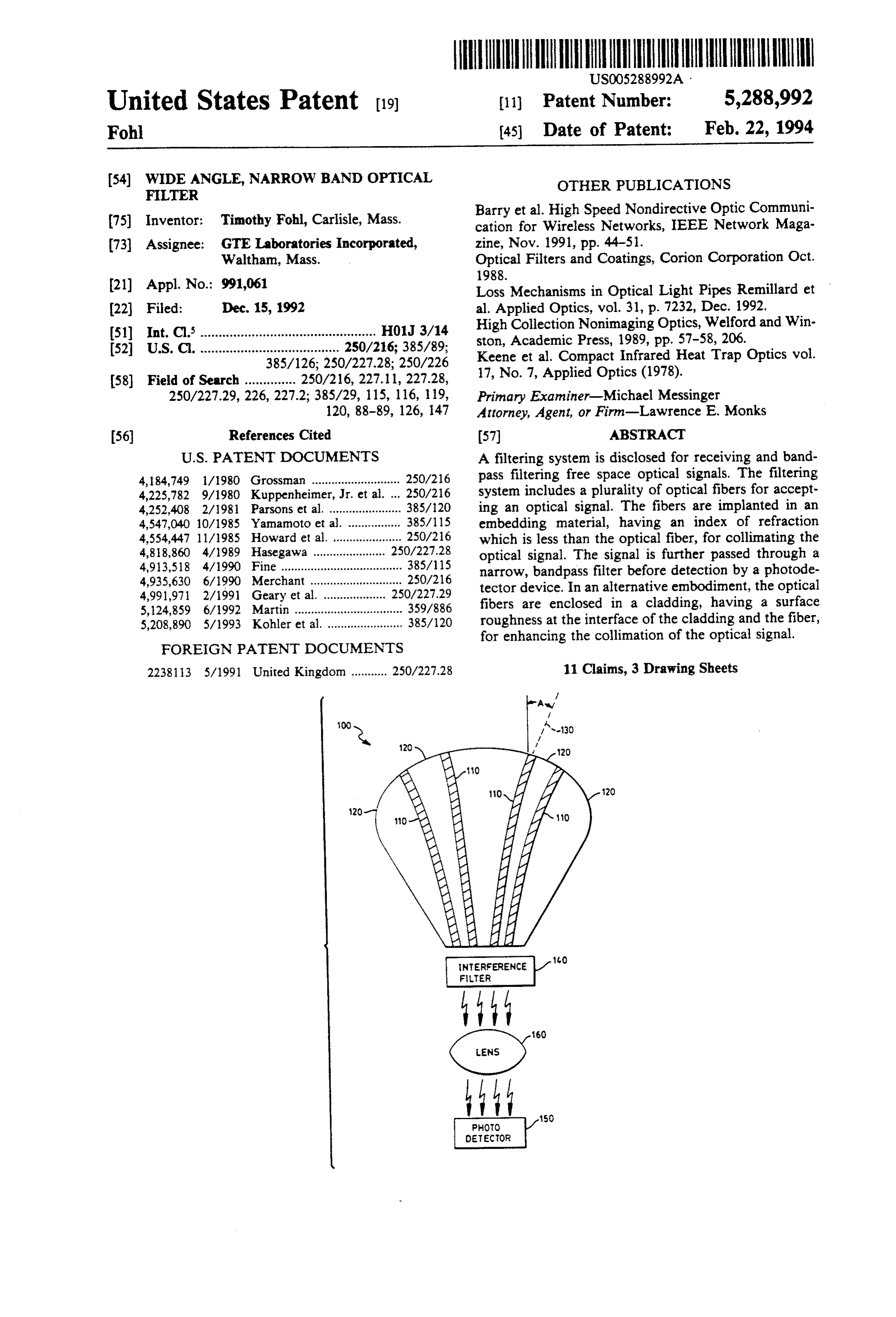
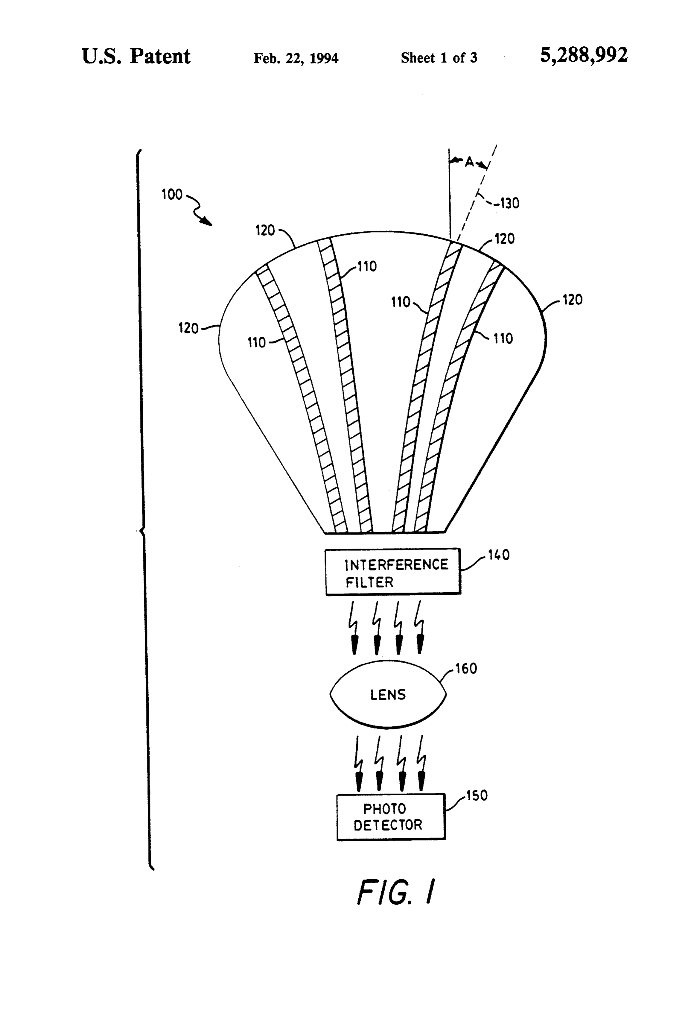
Narrow band optical systems have been developed for a 5 FIG. 1 is a cross sectional view of a filter system wide variety of applications for many years. The usual utilized in receiving free space optical signals in accor objective is to isolate an optical signal of a specific dance with the instant invention.
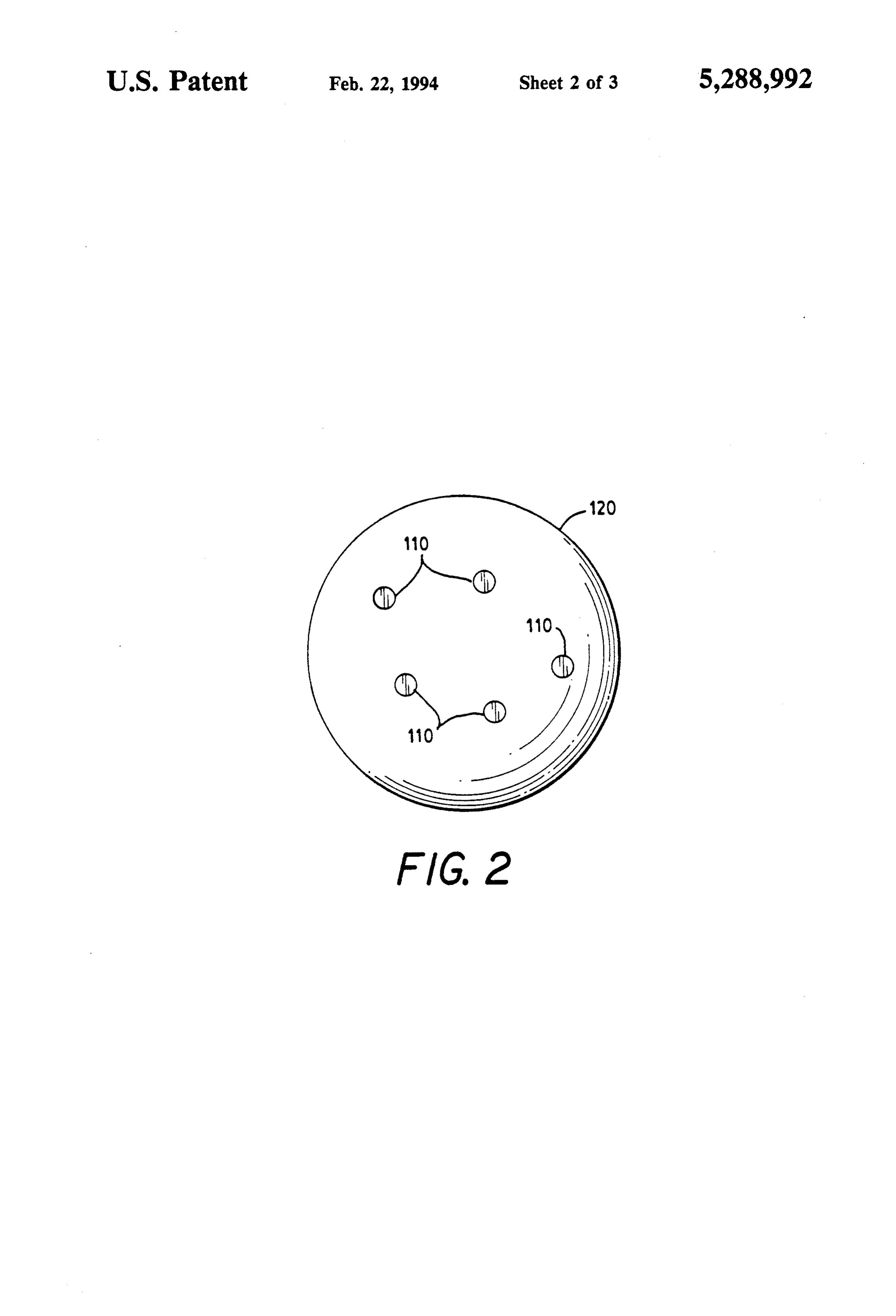
wavelength in the presence of a large flux of noise, i.e. FIG. 2 is a top view of a filter system utilized in optical radiation at other wavelengths. A better signal receiving free space optical signals in accordance with to noise ratio can be derived from the detector if the the instant invention.
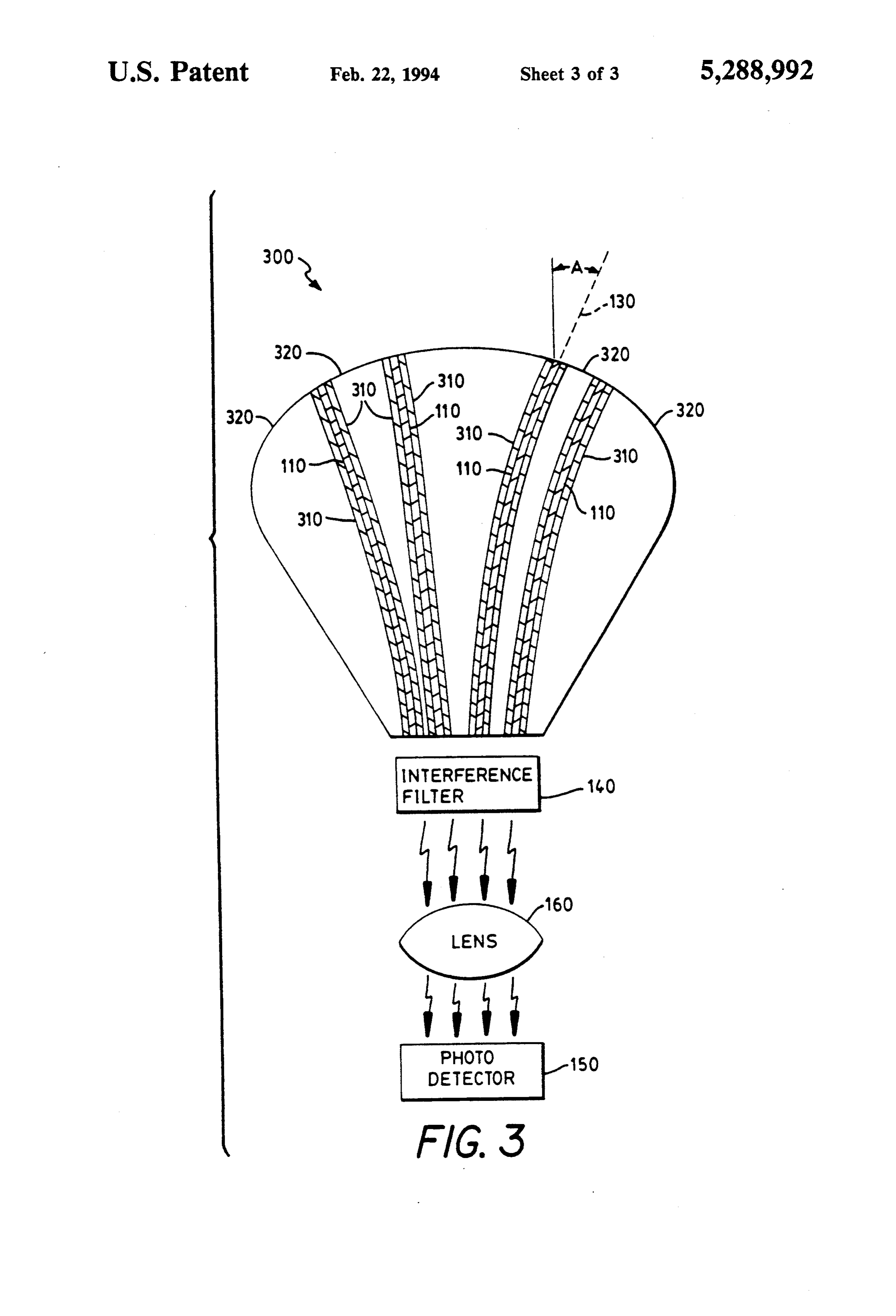
signal is within a narrow band of the optical spectrum. 20 FIG. 3 is a cross sectional view of an alternate em Noise is caused by background light outside the band of bodiment of a filter system utilized in receiving free the signal and such filters typically find use in wireless space optical signals in accordance with the instant communication applications as described by Barry et al. invention.
in "High-Speed Nondirective Optic Communication for DETAILED DESCRIPTION OF THE Wireless Networks", IEEE Network Magazine, Novem 25 INVENTION
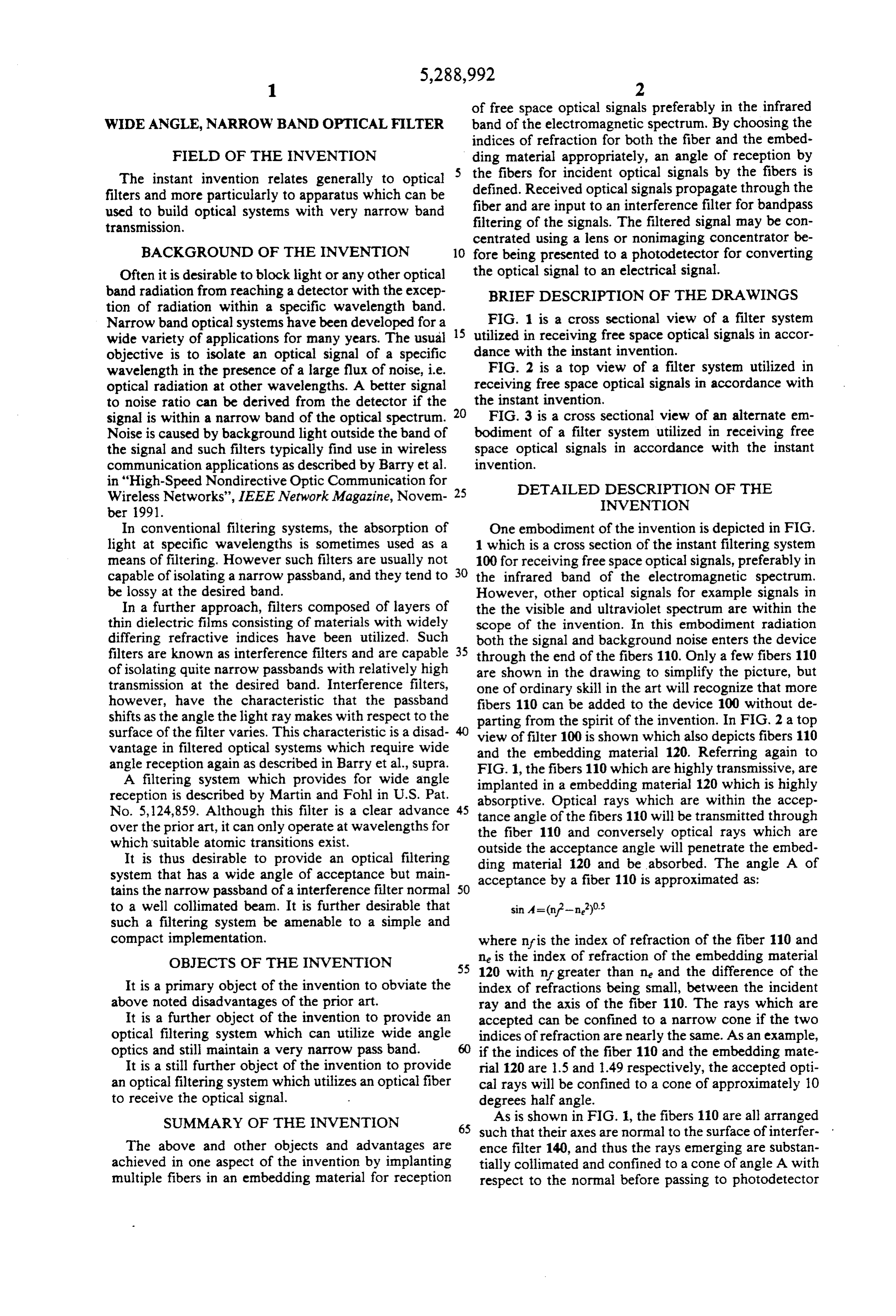
In conventional filtering systems, the absorption of One embodiment of the invention is depicted in FIG. light at specific wavelengths is sometimes used as a 1 which is a cross section of the instant filtering system means of filtering. However such filters are usually not 100 for receiving free space optical signals, preferably in capable of isolating a narrow passband, and they tend to 30 the infrared band of the electromagnetic spectrum. be lossy at the desired band. However, other optical signals for example signals in In a further approach, filters composed of layers of the the visible and ultraviolet spectrum are within the thin dielectric films consisting of materials with widely scope of the invention. In this embodiment radiation differing refractive indices have been utilized. Such both the signal and background noise enters the device filters are known as interference filters and are capable 35 through the end of the fibers 110. Only a few fibers 110 of isolating quite narrow passbands with relatively high are shown in the drawing to simplify the picture, but transmission at the desired band. Interference filters, one of ordinary skill in the art will recognize that more however, have the characteristic that the passband fibers 110 can be added to the device 100 without de shifts as the angle the light ray makes with respect to the parting from the spirit of the invention. In FIG. 2 a top surface of the filter varies. This characteristic is a disad vantage in filtered optical systems which require wide view and offilter 100 is shown which also depicts fibers 110 the embedding material 120. Referring again to angle reception again as described in Barry et al., supra. FIG. 1, the
A filtering system which provides for wide angle implanted infibers 110 which are highly transmissive, are a embedding material 120 which is highly reception is described by Martin and Fohl in U.S. Pat. absorptive. Optical rays which are within the accep No. 5,124,859. Although this filter is a clear advance 45 tance angle of the fibers 110 will be transmitted through over the prior art, it can only operate at wavelengths for the fiber 110 and conversely optical rays which are which suitable atomic transitions exist. outside the acceptance angle will penetrate the embed It is thus desirable to provide an optical filtering ding material 120 and be absorbed. The angle A of system that has a wide angle of acceptance but main acceptance by a fiber 110 is approximated as: tains the narrow passband of a interference filter normal 50 to a well collimated beam. It is further desirable that such a filtering system be amenable to a simple and compact implementation. where n?is the index of refraction of the fiber 110 and OBJECTS OF THE INVENTION ne is the index of refraction of the embedding material 55 120 with n? greater than ne and the difference of the
It is a primary object of the invention to obviate the index of refractions being small, between the incident above noted disadvantages of the prior art. ray and the axis of the fiber 110. The rays which are It is a further object of the invention to provide an accepted can be confined to a narrow cone if the two optical filtering system which can utilize wide angle indices of refraction are nearly the same. As an example, optics and still maintain a very narrow pass band. if the indices of the fiber 110 and the embedding mate It is a still further object of the invention to provide rial 120 are 1.5 and 1.49 respectively, the accepted opti an optical filtering system which utilizes an optical fiber cal rays will be confined to a cone of approximately 10 to receive the optical signal. degrees half angle.
SUMMARY OF THE INVENTION As is shown in FIG. 1, the fibers 110 are all arranged 65 such that their axes are normal to the surface of interfer
The above and other objects and advantages are ence filter 140, and thus the rays emerging are substan achieved in one aspect of the invention by implanting tially collimated and confined to a cone of angle A with multiple fibers in an embedding material for reception respect to the normal before passing to photodetector
Page 6
150. Interference filter 140 is of conventional design, In another embodiment of the invention, cladding 310 and is known by those skilled in the art. is highly absorptive of high angle rays entering fiber 110 The behavior of an interference filter 140 as rays which again enhances the collimating effect of fiber enter the filter away from the normal is described in 110. As an example, a black cladding is highly absorb Optical Filters and Coatings by Corion Corporation of 5 ing. Additionally, the loss of high angle rays entering Hopkington, Ma. (October 1988) and incorporated by the fibers is inversely proportional to the diameter of reference herein. Consequently, an estimate of the effec fiber 110 and can thus be engineered for a specific appli tive band pass of the filtering 100 system can be derived. cation of the filter system.
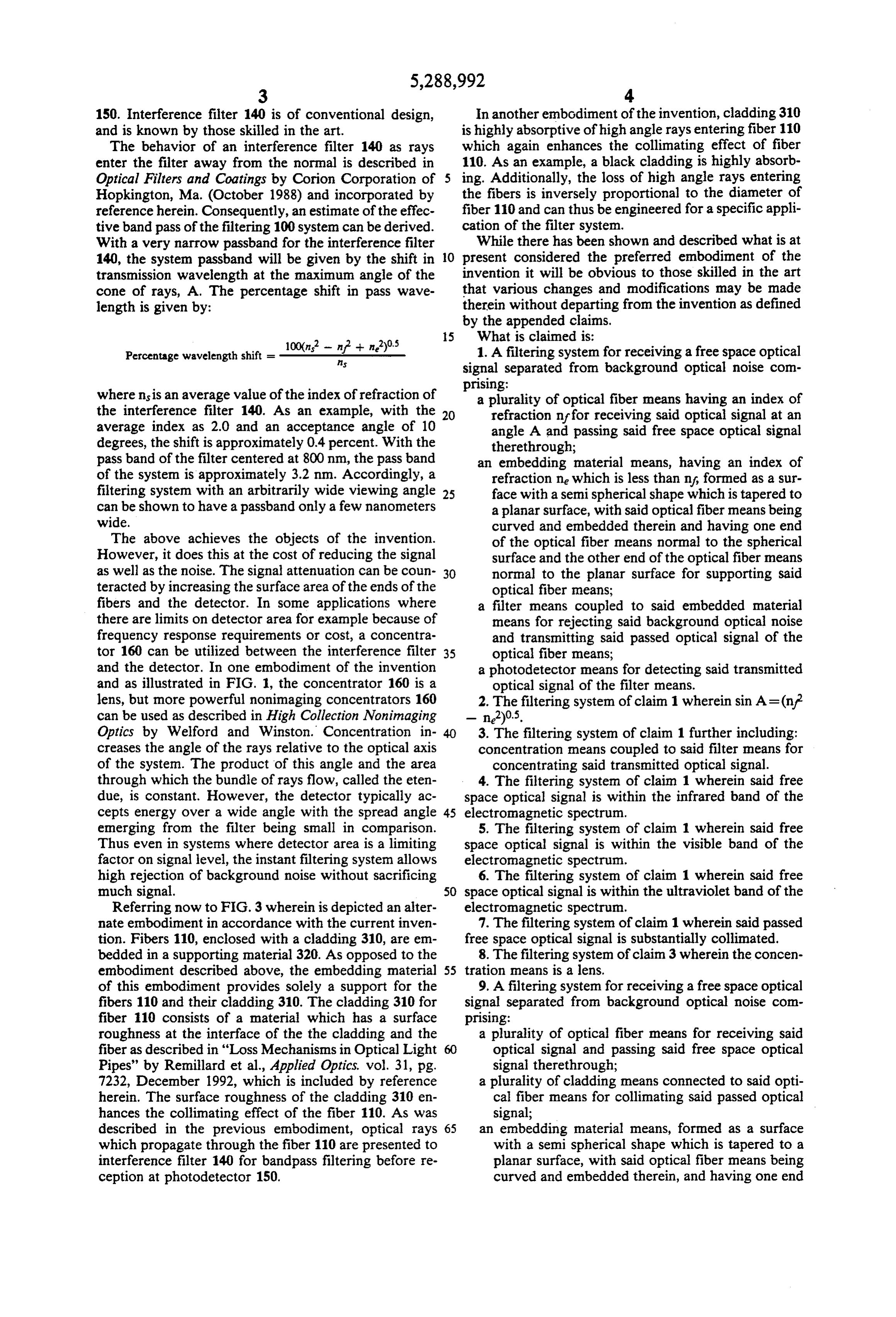
With a very narrow passband for the interference filter While there has been shown and described what is at 140, the system passband will be given by the shift in O present considered the preferred embodiment of the transmission wavelength at the maximum angle of the invention it will be obvious to those skilled in the art cone of rays, A. The percentage shift in pass wave that various changes and modifications may be made length is given by: therein without departing from the invention as defined by the appended claims.
Percentage wavelength shift = 10-ft 1. A filtering system for receiving a free space optical signal separated from background optical noise com prising:
where nsis an average value of the index of refraction of a plurality of optical fiber means having an index of the interference filter 140. As an example, with the 20 refraction inf for receiving said optical signal at an average index as 2.0 and an acceptance angle of 10 angle A and passing said free space optical signal degrees, the shift is approximately 0.4 percent. With the therethrough;
pass band of the filter centered at 800 nm, the pass band an embedding material means, having an index of of the system is approximately 3.2 nm. Accordingly, a refraction ne which is less than n?, formed as a sur filtering system with an arbitrarily wide viewing angle 25 face with a semispherical shape which is tapered to can be shown to have a passband only a few nanometers a planar surface, with said optical fiber means being wide. curved and embedded therein and having one end The above achieves the objects of the invention. of the optical fiber means normal to the spherical However, it does this at the cost of reducing the signal surface and the other end of the optical fiber means as well as the noise. The signal attenuation can be coun 30 normal to the planar surface for supporting said teracted by increasing the surface area of the ends of the optical fiber means;
fibers and the detector. In some applications where filter means coupled to said embedded material there are limits on detector area for example because of means for rejecting said background optical noise frequency response requirements or cost, a concentra and transmitting said passed optical signal of the tor 160 can be utilized between the interference filter 35 optical fiber means;
and the detector. In one embodiment of the invention a photodetector means for detecting said transmitted and as illustrated in FIG. 1, the concentrator 160 is a optical signal of the filter means. lens, but more powerful nonimaging concentrators 160 2. The filtering system of claim 1 wherein sin A=(nf can be used as described in High Collection Nonimaging - n2)05.
Optics by Welford and Winston. Concentration in 40 3. The filtering system of claim 1 further including: creases the angle of the rays relative to the optical axis concentration means coupled to said filter means for of the system. The product of this angle and the area concentrating said transmitted optical signal. through which the bundle of rays flow, called the eten 4. The filtering system of claim 1 wherein said free due, is constant. However, the detector typically ac space optical signal is within the infrared band of the cepts energy over a wide angle with the spread angle 45 electromagnetic spectrum.
emerging from the filter being small in comparison. 5. The filtering system of claim 1 wherein said free Thus even in systems where detector area is a limiting space optical signal is within the visible band of the factor on signal level, the instant filtering system allows electromagnetic spectrum.
high rejection of background noise without sacrificing 6. The filtering system of claim 1 wherein said free much signal. 50 space optical signal is within the ultraviolet band of the Referring now to FIG. 3 wherein is depicted an alter electromagnetic spectrum.
nate embodiment in accordance with the current inven 7. The filtering system of claim 1 wherein said passed tion. Fibers 110, enclosed with a cladding 310, are em free space optical signal is substantially collimated. bedded in a supporting material 320. As opposed to the 8. The filtering system of claim 3 wherein the concen embodiment described above, the embedding material 55 tration means is a lens.
of this embodiment provides solely a support for the 9. A filtering system for receiving a free space optical fibers 110 and their cladding 310. The cladding 310 for signal separated from background optical noise com fiber 110 consists of a material which has a surface prising:
roughness at the interface of the the cladding and the a plurality of optical fiber means for receiving said fiber as described in "Loss Mechanisms in Optical Light 60 optical signal and passing said free space optical Pipes' by Remillard et al., Applied Optics, vol. 31, pg. signal therethrough;
7232, December 1992, which is included by reference a plurality of cladding means connected to said opti herein. The surface roughness of the cladding 310 en cal fiber means for collimating said passed optical hances the collimating effect of the fiber 110. As was signal;
described in the previous embodiment, optical rays 65 an embedding material means, formed as a surface which propagate through the fiber 110 are presented to with a semispherical shape which is tapered to a interference filter 140 for bandpass filtering before re planar surface, with said optical fiber means being ception at photodetector 150. curved and embedded therein, and having one end
Page 7
of the optical fiber means normal to the spherical a photodetector means for detecting said transmitted surface and the other end of the optical fiber means optical signal of the filter means. normal to the planar surface for supporting said 10. The filtering system of claim 9 wherein said clad optical fiber means; ding means has a rough surface at the connection to the filter means coupled to said embedded material 5 optical fiber means.
means for rejecting said background optical noise 11. The filtering system of claim 9 wherein said clad and transmitting said passed optical signal of the ding means is highly absorptive.
optical fiber means; k . . . .
Provenance
- Collection
- Cited prior art
- Original PDF
- patentimages.storage.googleapis.com →
- Filed
- 1992-12-15
- Pages
- 7
- Method
- pdftotext (the PDF's own text layer) + pdftoppm 300dpi page scans
- Source
- Google Patents bibliographic record
- Granted
- 1994-02-22
- Inventors
- Timothy Fohl; GTE Laboratories Inc
- Transcribed from
- patentimages.storage.googleapis.com →