patent · US4053683
System for fuel supplementation
11 October 1977
Page 1 — bibliographic record
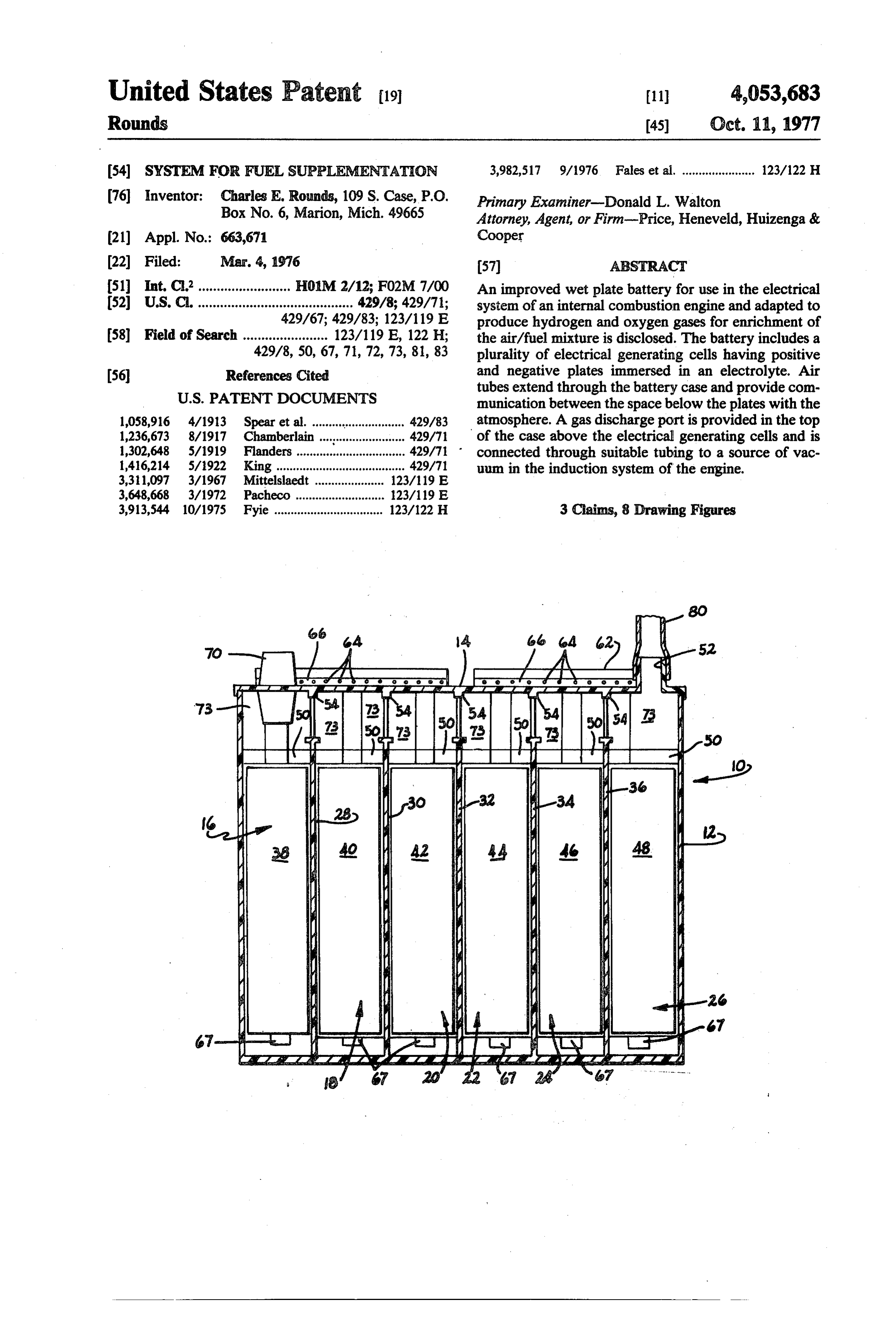
United States Patent (19) 11 4,053,683 Rounds 45) Oct. 11, 1977 (54) SYSTEM FORFUEL SUPPLEMENTATION 3,982,517 9/1976 Fales et al. ...................... 123/122 H 76) Inventor: Charles E. Rounds, 109 S. Case, P.O. Primary Examiner-Donald L. Walton Box No. 6, Marion, Mich. 49665 Attorney, Agent, or Firm-Price, Heneveld, Huizenga & (21) Appl. No.: 663,671 Cooper 22 Filed: Mar. 4, 1976 (57) ABSTRACT 51 Int, C.’......................... HOM 2/12; F02M 7/00 An improved wet plate battery for use in the electrical (52) U.S.C. .......................................... 429/8; 429/71; system of an internal combustion engine and adapted to 429/67; 429/83; 123/119 E produce hydrogen and oxygen gases for enrichment of 58 Field of Search ....................... 123/119 E, 122 H; the air/fuel mixture is disclosed. The battery includes a 429/8, 50, 67, 71, 72,73, 81, 83 plurality of electrical generating cells having positive (56) References Cited and negative plates immersed in an electrolyte. Air
tubes extend through the battery case and provide com munication between the space below the plates with the 1,058,916 4/1913 Spear et al. ............................ 429/83 atmosphere. A gas discharge port is provided in the top 1,236,673 8/1917 s 429/71 of the case above the electrical generating cells and is 1,302,648 5/1919 . 429/71 connected through suitable tubing to a source of vac 1,46,214 5/1922 429/71 uum in the induction system of the engine. 3,311,097 3/1967 Mittelslaedt. 123/119 E 3,648,668 3/1972 Pacheco ........................... 123/119 E 3,913,544 10/1975 Fyie ................................. 123/122 H 3 Cairns, 8 Drawing Figures
aaaad All 4744 AAAAYA
Page 2
Drawing sheet — no readable text.
Page 3
Drawing sheet — no readable text.
Page 4
Drawing sheet — no readable text.
Page 5
A similar system is disclosed in U.S. Pat. No.
SYSTEM FOR FUEL SUPPLEMENTATION 3,311,097 to Mittelstaedt, entitled HYDROGEN-OXY BACKGROUND OF THE INVENTION GEN DEVICE IN COMBUSTION ENGINES, and issued on Mar. 28, 1967. The storage battery disclosed
This invention relates to enrichment of the air/fuel 5 therein for producing oxygen and hydrogen gases for mixture of an internal combustion engine and more air/fuel mixture enrichment is provided with an air particularly to enrichment with oxygen and hydrogen intake opening.
gases produced in a wet plate storage battery which above the cells When of the a vacuum is applied to the space battery, ambient air is drawn in forms a part of the electrical system of the internal through the intake opening and across the space above combustion engine. 10 the cells. This feature apparently increases the amount
Typically, the electrical systems employed with an of gases which pass to the venturi of a conventional internal combustion engine, for example of the type carburetor. Further, it appears that this employed in automobiles, includes a generator or alter air assists in cooling the battery duringflow of ambient engine opera nator, a voltage regulator, a rechargeable or storage 15 tion.
battery of the lead-acid type, an ignition switch, an With all of the systems of the type exemplified by the ignition coil, a distributor, and a plurality of sparkplugs. above discussed patents, certain problems are present. During engine operation, electricity generated by the generator or alternator is directed to the rechargeable For example, during the recharging process in the nor battery to maintain the battery charge so as to meet the 20 mal storage battery polarization increases the resistance variable loads imposed on the battery during use. of the battery and therefore requires an increase in the The typical lead/acid storage battery includes a plu charging voltage to maintain the charging current flow. rality of cells connected in series with each cell produc Further, during the discharge process, water is formed ing approximately 2 volts. Each electrical generating adjacent the positive plates. In cold weather, this results cell includes a negative plate group and a positive plate 25 in an increased tendency for freezing at the positive group. Each plate is formed by a lattice-like grid of an plates. The need therefore exists, for a hydrogen-oxy alloy of lead and antimony and the grids are filled with gen generator capable for use as a primary storage bat a special lead-oxide paste. The amount of current pro tery in a vehicle electrical system which produces a duced by the storage battery is determined by the active fairly large amount of gases for enrichment without an area and weight of the materials in the plates and also by increase in internal resistance caused by polarization the quantity of electrolyte which is typically a dilute 30 and further maintains sufficient mixing of the electro sulfuric acid solution. The positive plate material is lyte to prevent freezing adjacent the positive plates in essentially lead peroxide and the active material of the cold weather.
negative plate is spongy lead. The electrolyte is a solu tion of sulfuric acid and water. When an electrical load 35 SUMMARY OF THE INVENTION is placed across the positive and negative terminals of In accordance with the present invention an in the battery, oxygen in the lead peroxide combines with proved wet plate battery is provided as well as a the hydrogen from the sulfuric acid to form water. At method for enriching the air/fuel mixture of an internal the same time, the lead in the lead peroxide combines combustion engine whereby the problems heretofore with the sulfate of the acid to form lead sulfate. At the experienced are substantially alleviated. Essentially, the negative plate, the lead combines with the sulfate of the wet plate battery in accordance with the present inven sulfuric acid to form lead sulfate. The battery is re tion includes an electrical generating cell disposed charged by directing a charging current through the within a case. The cell includes positive and negative battery in the reverse direction of the discharging cur plates rent. During charge, the water in the electrolyte is 45 tube iswhich are immersed within an electrolyte. An air broken down into hydrogen and oxygen through elec has one end open which provided extends through the case and to atmosphere exteriorly of the case, trolysis. The oxygen collects at the positive plate and The other end of the air tube opens adjacent the bottom the hydrogen collects at the negative plate. The collec of the cell and is immersed in the electrolyte. A gas tion of the gas layer at each plate increases the internal resistance of the cell and therefore an increase in charg 50 discharge port is formed in the top surface of the case. ing voltage is necessary to maintain the same charging This port is adapted to be connected to a source of vacuum in the engine induction system.
current flow.
: Heretofore, it has been proposed to employ the hy As a result of this arrangement, as the vacuum is drogen and oxygen produced during battery recharge applied to the gas collection space above the cell, ambi to supplement and/or enrich the air/fuel mixture em 55 ent air is drawn downwardly through the air tube and ployed in the internal combustion engine. An example bubbles upwardly through the electrolyte. The air then of one such system may be found in U.S. Pat. No. passes with the liberated oxygen and hydrogen through 1,876,879 to Drabold, entitled CHARGE FORMING the gas discharge port to the induction system of the APPARATUS FOR INTERNAL COMBUSTION engine. By drawing air through the electrolyte of the
ENGINES, and issued on September 13, 1932. As battery, the electrolyte is sufficiently agitated to pre shown therein, hydrogen produced in the main storage vent the formation of a gas layer on the plates. The battery of the vehicle ignition and electrical system is arrangement maintains the electrolyte in a sufficiently collected by a plurality of tubes opening into the space mixed or agitated state to prevent freezing adjacent the above the electrolyte. The gases are directed via a vac positive plates. Further, the airflow passing up through uum line to the throat of a conventional venturi-type 65 the electrolyte increases the amount of gases liberated carburetor. The Drabold arrangement collects only the through the surface of the electrolyte and also assists in gas which is present above the electrolyte during charg scavenging the oxygen and hydrogen from the gas col ing of the main storage battery. lection space to the gas discharge port.
Page 6
charge port and tube while restraining or eliminating
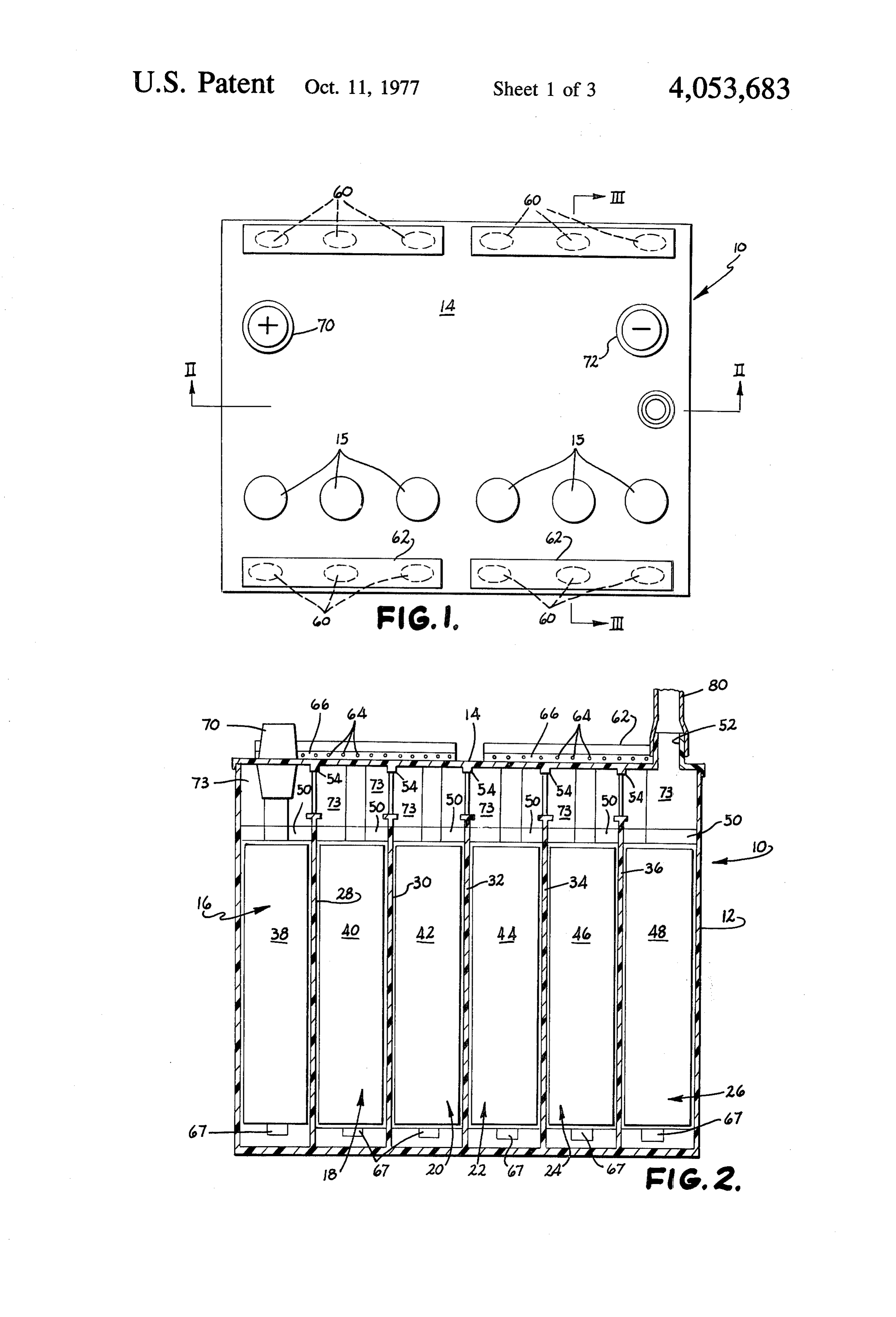
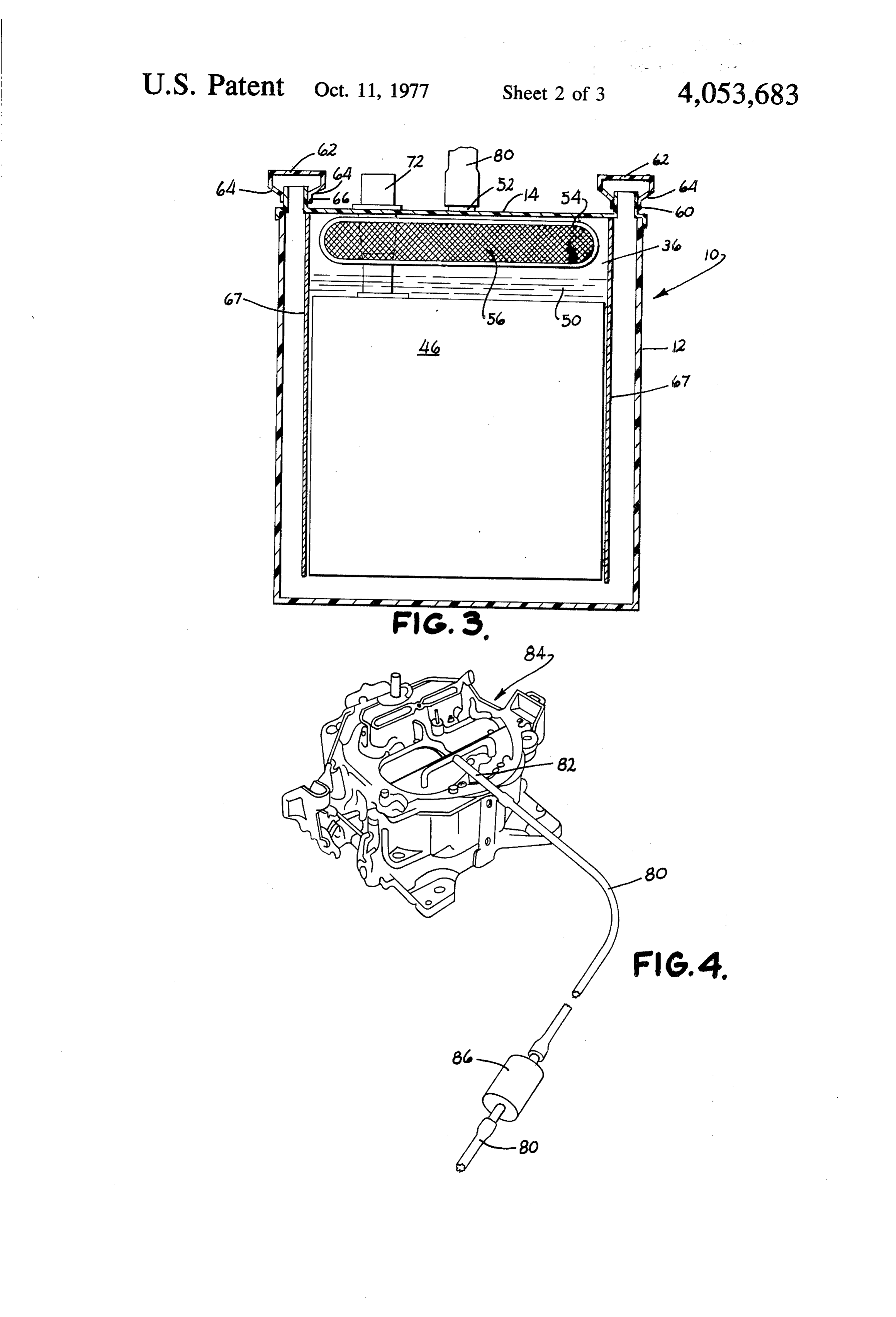
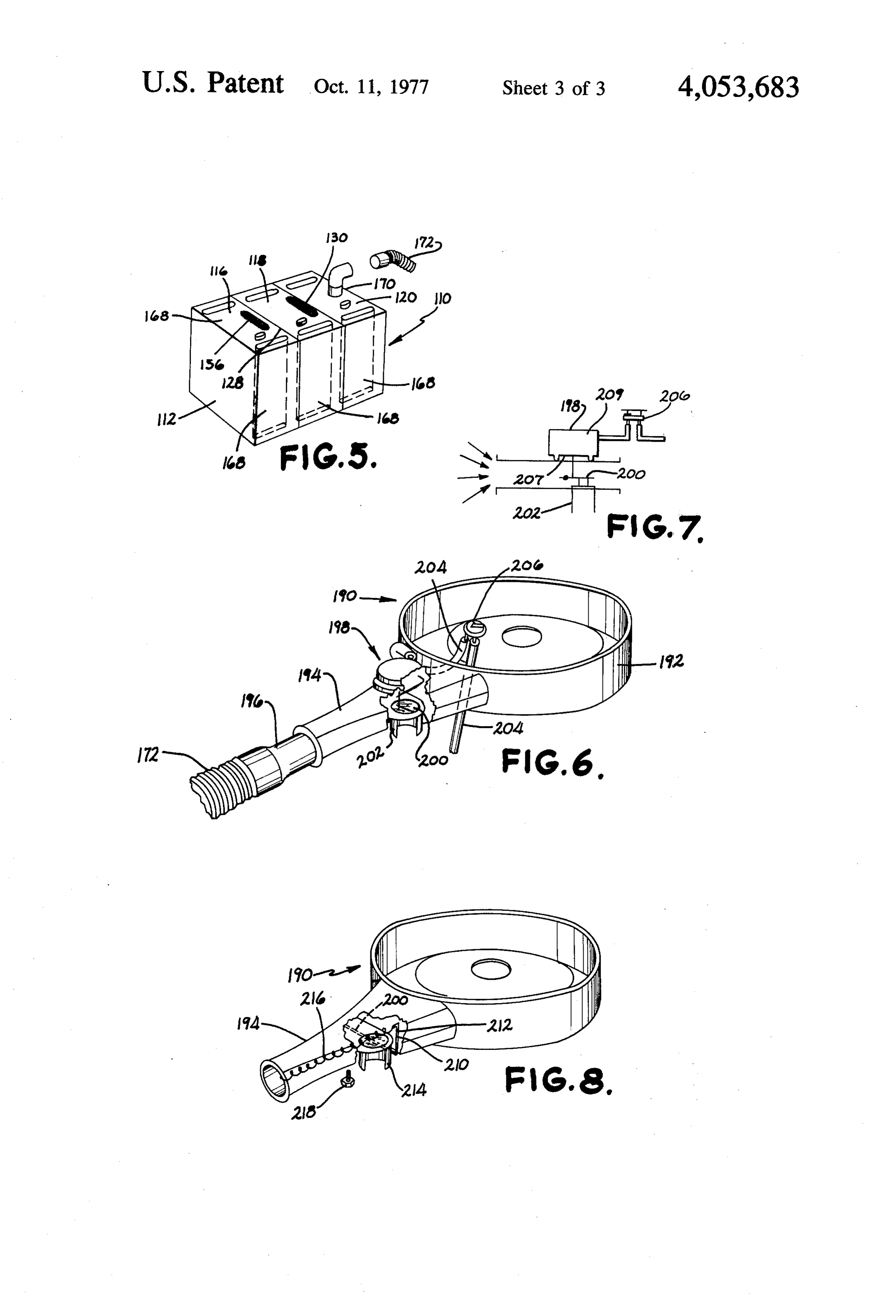
BRIEF DESCRIPTION OF THE DRAWINGS the passage of the liquid electrolyte. FIG. 1 is a plan view of a wet plate battery in accor As best seen in FIGS. 1-3, the upper wall or top dance with the present invention; cover 14 of the battery case includes a plurality of inlet FIG.2 is a cross-sectional, side elevational view taken 5 ports or passages 60. The inlet ports 60 are longitudi along line II-II of FIG. 1; nally spaced and extend along each lateral edge of the FIG. 3 is a cross-sectional, elevational view taken cover 14. Therefore, each generating cell includes two along line III-III of FIG. 1; air intake ports. The ports 60 may be formed in a row FIG. 4 is a view illustrating the manner in which the with the cover 14 during the molding operation or they battery of FIGS. 1-3 may be connected to the induction 10 may take the form of separate, tubular inserts press fit system of an internal combustion engine; and secured by suitable adhesives within apertures FIG. 5 is a perspective view of an alternative form of formed in the cover. As seen in FIGS. 1 and 2, the air battery in accordance with the present invention; inlet ports 60 are divided into groups of three. Each FIG. 6 is a perspective, fragmentary view showing an group of three includes a common intake shroud 62. alternative connection to the air cleaner system of an 15 The intake shroud is press fit over the intake ports and engine; includes a plurality of air inlet apertures 64 formed in a FIG. 7 is a fragmentary, side elevational view in cross lower side wall 66. The intake shroud 62 serves to per section of the air cleaner system of FIG. 6; and mit ingress of ambient air while effectively preventing FIG. 8 is a perspective, fragmentary view of an alter 20 the ingress of undesired contaminants and/or liquids. A filter-like material may be disposed within the shroud 62 native air cleaner system. to more effectively prevent the ingress of dust and other DETAILED DESCRIPTION OF THE particulate contaminants.
PREFERRED EMBODIMENT As best seen in FIGS. 2 and 3, the lower open end of One embodiment of an improved wet plate storage 25 each air inlet port 60 is in communication with the downwardly extending air passage tube 67. Each air battery in accordance with the present invention is passage tube 67 is effectively sealed at its upper end by illustrated in FIGS. 1-3 and generally designated 10. As the cover 14. Each tube 67 may be formed as part of the shown, the battery 10 includes a case 12 formed of a case during the molding operation or the tubes may be rubber-type or hard plastic material which is resistant to corrosion. The molded case 12 includes a top 14. The 30 separate forming.
inserts positioned in the battery case after
For reasons which will become readily appar top 14 is illustrated as a separate member and includes a ent, each air passage tube 67 extends from an air inlet plurality of non-vented fill caps 15. As best seen in FIG. port 60 to a point below each cell plate group. 2, the case 12 is divided into a plurality of electrical As in conventional battery ignition systems, the posi generating cells 16, 18, 20, 22, 24 and 26, all of which are connected in series. In the typical lead-acid storages tive terminal 70 and the negative terminal 72 are in electrical connection with the alternator or generator of battery, each electrical generating cell is capable of the charging system. As a result, during battery charge, producing a two volt output. Therefore, the battery oxygen gas will be formed adjacent the positive plate shown in the drawings as having six cells is a 12 volt groups and hydrogen gas will be formed adjacent the type battery. negative plate groups of each generating cell. These Each of the electrical generating cells is defined by 40 gases will collect above the electrolyte in the gas collec the side and bottom walls of the case 12 and by a plural tion spaces 73.
ity of cell dividing walls 28, 30, 32, 34 and 36 which are An exhaust tube 80 is sealably connected at one-end to formed as part of the case during the case molding the exhaust port 52. As best seen in FIG. 4, the exhaust operation. Each electrical generating cell includes a tube 80 extends from the exhaust port 52 to a gas induc conventional positive and negative plate group 38, 40, 45 tion orifice tube 82. The orifice tube 82 is supported on 42, 44, 46 and 48 respectively, illustrated schematically a conventional carburetor 84 adjacent the throat area of in FIGS. 2 and 3. In the typical lead-acid storage bat the carburetor air horn. The carburetor is shown for tery, the positive plates are formed from a composition illustrative purposes only as being of the multi-valve or including lead peroxide, and the negative plates are multi-barrel type. An orifice tube having a single outlet, formed from a composition including spongy lead. The 50 of course, may be employed. Further, it is preferred that case 12 is filled to a point just below the tops of the a conventional back pressure-type check valve 86 be dividing walls with a liquid electrolyte 50 such as a inserted at some point in exhaust tube 80. The back water-sulfuric acid solution. As shown, the lower end of pressure check valve 86 is inserted in the exhaust line 80 each of the plate groups terminates above the bottom in order to insure that gases flow only to the carburetor wall of the case. This space is primarily provided to 55 and to prevent flow of gases from the carburetor back reduce the chance of grounding out of the positive to the battery.
plates by the precipitates which collect at the bottom of Having fully described the structural arrangement of the case. m the improved wet plate battery, the method of opera As best seen in FIGS. 2 and 3, each dividing wall 28, tion will now be more fully described. As is apparent, 30, 32, 34 and 36 is formed with an elongated aperture during engine operation a low pressure are will be cre 54. Positioned within each aperture 54 is a fine mesh ated at the gas induction orifices. This will impress a type filter screen 56. The walls in conjunction with the vacuum or reduced pressure area over each generating battery case define a plurality of gas collection cham cell at the gas collection chamber. As a result of this bers. A gas discharge tube 52 is formed in the cover 14 vacuum, ambient air will be drawn in through the inlet and is in communication with the gas collection cham 65 ports 60 and downwardly through the air admission bers. As will be more fully described below, the mesh tubes 67. The air will exit from the tubes below the plate screens allow air and other gases collected in the gas groups of each generating cell and will therefore bubble collection chambers to pass unrestricted to the gas dis upwardly through the electrolyte. During engine oper
Page 7
ation, the gases formed will be forced upwardly by the intake snorkel 194. A transition tube 196 inserted into air bubbling through the electrolyte. The agitation of the opening of the snorkel 194 permits a sealed connec the electrolyte will assist in preventing polarization by tion of exhaust tube 172 to the snorkel. insuring that the gas layer formed at either of the plate The conventional air cleaner includes a vacuum actu groups is removed. The agitation insures constant mix ated damper unit 198 having a butterfly-type valve 200 ing of the electrolyte resulting in optimum battery per rotatably mounted within the snorkel adjacent a heated formance and preventing freezing adjacent the positive air delivery tube 202. Air is supplied to tube 202 from a plate during cold weather operation. Further, the agita stove arrangement (not shown) mounted adjacent the tion assists in reducing the surface tension at the inter exhaust manifold. A vacuum line 204 connects the unit face between the electrolyte and the gas in the gas col 10 198 with a source of vacuum through a temperature lection chambers. This feature insures that more of the sensitive vacuum bleed valve 206. oxygen and hydrogen generated during the charging During cold operating conditions, the valve element process will escape from the electrolyte and be drawn 200, which is connected to a diaphragm 207, closes off through the exhaust port 52. If desired, a glass wool-like the snorkel inlet and heated air is drawn up tube 202 and material may be placed at the electrolyte surface to 15 into the filter housing 192 (FIG. 7). As the operating further reduce the surface tension. The mesh filters 56 temperature of the engine increases, the sensing unit and insure that the gases are effectively removed from the bleed valve 206 will open and progressively bleed off gas collection chambers substantially free of the liquid the vacuum applied to the diaphragm 207 within the electrolyte. Also, by passing the ambient air down unit 198. A spring 209 within the unit will then rotate wardly and then upwardly through the electrolyte, valve 200, thereby closing off inlet tube 202 and permit there is an improvement in battery cooling over that ting air to enter the carburetor from battery exhaust heretofore found in the prior art batteries. The vacuum tube 172. Since the position of the damper valve 200 is available from the carburetor should be sufficient to a function of intake manifold pressure and engine tem draw ambient air through the battery. If a sufficient perature, the amount of outside air mixed with the air vacuum is not available at this source, a small, conven 25 and gases drawn from the battery will vary as a function tional vacuum pump could be inserted in tube 80. This of intake manifold pressure, engine speed and tempera pump would then provide the required boost in vacuum ture. With this embodiment, due to the increased flow level. rates through the battery, glass wool should be placed By enriching the air/fuel mixture ingested by the at the electrolyte surface in the gas collection space to internal combustion engine, various advantages are 30 reduce electrolyte surface tension.
realized. For example, the efficiency of the engine is A manually adjustable damper assembly is illustrated increased. This is believed to be the result of more com in FIG. 8. This arrangement is usable with older vehi plete combustion resulting from induction of the hydro cles not having the automatic air mix system of FIG. 6. gen gas. As a result, the internal combustion engine As shown, a damper valve 200 is rotatably mounted on should operate with increased power, better fuel econ 35 a shaft 210 having a right angled portion 212. The valve omy, as well as with a reduction in carbon buildup in is positioned over an outside air inlet 214. A spring or the combustion chamber. Since the battery is effectively other resilient means 216 hooked to the snorkel and the sealed and all gases produced are discharged to the portion 212 biases the valve to a closed position wherein engine induction system, corrosion at the battery termi the total air requirements are filled from the ambient nals is reduced. Also, the danger of explosion at the source. An air adjustment member 218 is received battery during engine operation is eliminated. This lat within a threaded aperture in the snorkel. The screw ter danger is always present in batteries which have 218 contacts a transverse area of the valve element. By vented filler caps permitting the explosive gases to col screwing the member 218 into the snorkel, the valve 200 lect adjacent the top of the battery in the engine com is pivoted against the bias of the spring 216, thereby partment. 45 partially or wholly closing the ambient air tube or inlet An alternative construction for the wet plate battery 194 and permitting the induction of air and gas from the is illustrated in FIG. 5. As shown therein, the battery battery.
110 includes a molded case 112. The case 112 is divided By providing a sufficiently long and flexible exhaust into cells 116, 118 and 120 by walls 128 and 130. As in tube 172, the induction pulsations may be effectively the previous embodiment, the cell dividing walls 128, 50 dampened. Thus, a fairly even vacuum may be applied 130 each include an elongate aperture 154. A fine mesh at the gas collection chamber of the battery. type filter screen 156 is positioned within each aperture. Although the present arrangement has been described In this embodiment, a pair of spaced air passage tubes with the improved wet plate battery serving as the 168 extend from the cover 114 of the case downwardly storage battery of a vehicle ignition and electrical sys below the electrolyte within each cell. The tubes 168 55 tem, it, of course, would be possible to provide a sepa are generally oval or flattened in cross section having a rate battery to satisfy the electrical requirements of the transverse dimension almost equal to the width of each vehicle. In such case, the improved lead-acid type wet cell. As a result, the tubes 168 provide an increased flow plate battery of the present invention would be sepa area when compared with the tubes 16 of FIG. 3. rately connected to the vehicle generating system or to As with the previous embodiment, an exhaust port a separate generator. It is believed that if a sufficient 170 is connected to an exhaust tube 172. Exhaust tube number of hydrogen fuel generators or batteries in ac 172, however, is connected to an air cleaner assembly cordance with the present invention were provided, the 190 shown in FIGS. 6 and 7. With this arrangement, the internal combustion engine could be operated solely on larger air passage tubes 168 are required since substan hydrogen gas thereby eliminating the need for gasoline. tially the entire air requirement for the engine may be 65 It can therefore be appreciated that the present inven drawn through the electrolyte within the battery. The tion provides an improved wet plate battery for the air cleaner assembly 190 is of a conventional construc production of hydrogen gas for fuel enrichment as well tion including a filter receiving housing 192 and an air as an improved method for enriching the air fuel mix
Page 8
ture of a conventional internal combustion engine. It is a plurality of electrical generating cells within said expressly intended that the foregoing description be case, each cell including positive and negative illustrative of the preferred embodiments only. The true plates;
spirit and scope of the present invention will be deter a plurality of wall members separating each cell mined by reference to the appended claims. 5 within said case, each wall member having an aper The embodiments of the invention in which an exclu ture thereby placing the area above each cell in sive property or privilege is claimed are defined as communication with the adjacent cell; follows. a plurality of air tubes extending from the top of said 1. An improved wet plate battery for use with an case downwardly within each of said cells, said air internal combustion engine carburetor and adapted to 10 tubes being open at their ends with the lower end produce oxygen and hydrogen gas for enriching the terminating adjacent the bottom of said case; air/fuel mixture inducted into the internal combustion a gas discharge port formed in the top of said case; engine, comprising: means disposed within said cell wall apertures for a case; permitting the gases collecting above said plates to a plurality of electrical generating cells separated by a 15 pass to said gas discharge port while restraining plurality of separating walls within said case, each passage of electrolyte;
having positive and negative plates, said plates a gas exhaust tube connected at one end to said port being immersed in a dilute electrolyte; and at the other end to said air cleaner assembly, a plurality of air tubes extending into said cells, each 20 said air cleaner assembly including an outwardly tube extending into one cell and said air tubes each extending air intake snorkel, said other end of said having one end open to atmosphere exteriorly of tube being connected to the inlet of said snorkel said case and having the other end open below said whereby at least a portion of the air requirements of electrolyte level in said cell, below said plates and the engine are supplied by air drawn downwardly being immersed in said electrolyte; through said air tubes and through said battery, said a gas discharge port disposed on the top of said case 25 snorkel having an aperture therein downstream of above the electrolyte and adapted to be connected the snorkel inlet communicating the interior of said to a source of vacuum at the carburetor, each of snorkel with ambient air; and a damper valve means said cell separating walls having an aperture above disposed within said snorkel and having a valve the electrolyte; element for partially or wholly closing said ambient means disposed within said separating wall apertures 30 air aperture and for varying the ratio of ambient air for permitting the gases collecting above said plates to gases from said battery supplied to said engine as to pass to said gas discharge port while restraining a function of intake manifold pressure and engine temperature.
passage of the electrolyte; 3. The combination definded by claim 2 wherein said a plurality of intake shrouds positioned above said air 35 valve means includes:
tubes, said shrouds having a plurality of apertures a damper valve element rotatably mounted within communicating a plurality of said tubes with atmo said snorkel;
sphere; resilient means connected to said valve element for a gas discharge tube sealably connected at one end to biasing said valve to a position wherein substan said gas discharge port, said gas discharge tube 40 tially all the air requirements are supplied from the adapted for connection to the carburetor of the ambient air; and engine; and w adjustable valve position means mounted to said snor a check valve inserted intermediate the ends of said kel and engaging said valve element for selectively discharge tube. varying the position of said valve element as a func 2. In combination with an air cleaner assembly of an 45 tion of intake manifold pressure and engine temper internal combustion engine, an improved wet plate bat ature thereby varying the ratio of ambient air to tery comprising: gases from said battery supplied to said engine. a molded case;
Provenance
- Collection
- Cited prior art
- Original PDF
- patentimages.storage.googleapis.com →
- Filed
- 1976-03-04
- Pages
- 8
- Method
- pdftotext (the PDF's own text layer) + pdftoppm 300dpi page scans
- Source
- Google Patents bibliographic record
- Granted
- 1977-10-11
- Inventors
- Charles E. Rounds
- Transcribed from
- patentimages.storage.googleapis.com →