patent · US4038557
Particulate energy absorber
26 July 1977
Page 1 — bibliographic record
United States Patent (19) 11) 4,038,557 Gildersleeve, Jr. et al. 45) July 26, 1977 (54) PARTICULATE ENERGY ABSORBER 3,203,167 8/1965 Green, Jr. .............................. 60/641 3,287,910 1 1/1966 Silverstein ............................. 60/203 76) Inventors: Oliver DeP. Gildersleeve, Jr., 109 3,866,332 2/1975 Hertz ............ ... 159/DIG. 3 Deepdale Road, Strafford, Pa. 19087; 3,892,433 7/1975 Blake N. ... 290/2 George A. Hunger, Jr., 410 W. Primary Examiner-Robert S. Macon
Palmer St., Morrisville, Pa. 19067 Attorney, Agent, or Firm-Paul & Paul 21). Appl. No.: 549,152 57 ABSTRACT 22) Filed: Feb. 12, 1975 Radiant energy is converted to thermal energy utilizing 51 int. C.’.......................... H02P 9/04; G02B5/10 forced convection through a fluidized bed. The bed is (52) U.S.C. ............................. 290/1 R; 159/DIG. 3; made up of solid, radiant energy absorbing solids in 60/203; 60/641 particulate form, which are maintained in fluidized con (58) Field of Search ................. 290/1, 2; 159/DIG. 3, dition by passage of a gas therethrough. Radiant energy 159/4 K, 24 A; 60/641, 203 impinges upon and is absorbed by the bed, and in turn is transferred thermally to the gas. The gas may be uti 56) References Cited . lized to drive a gas turbine power generator, may be
2,968,916 1/1961 Taylor et al. .......................... 60/641 like.
2,969,637 1/1961 Rowekamp....... 60/641 3,083,528 4/1963 Brown .................................... 60/203 24 Claims, 5 Drawing Figures
GAS FLOWOUT
PRESSURIZED.
GAS
Page 2
Drawing sheet — no readable text.
Page 3
Drawing sheet — no readable text.
Page 4
Drawing sheet — no readable text.
Page 5
gas which is passing through the particles as it maintains
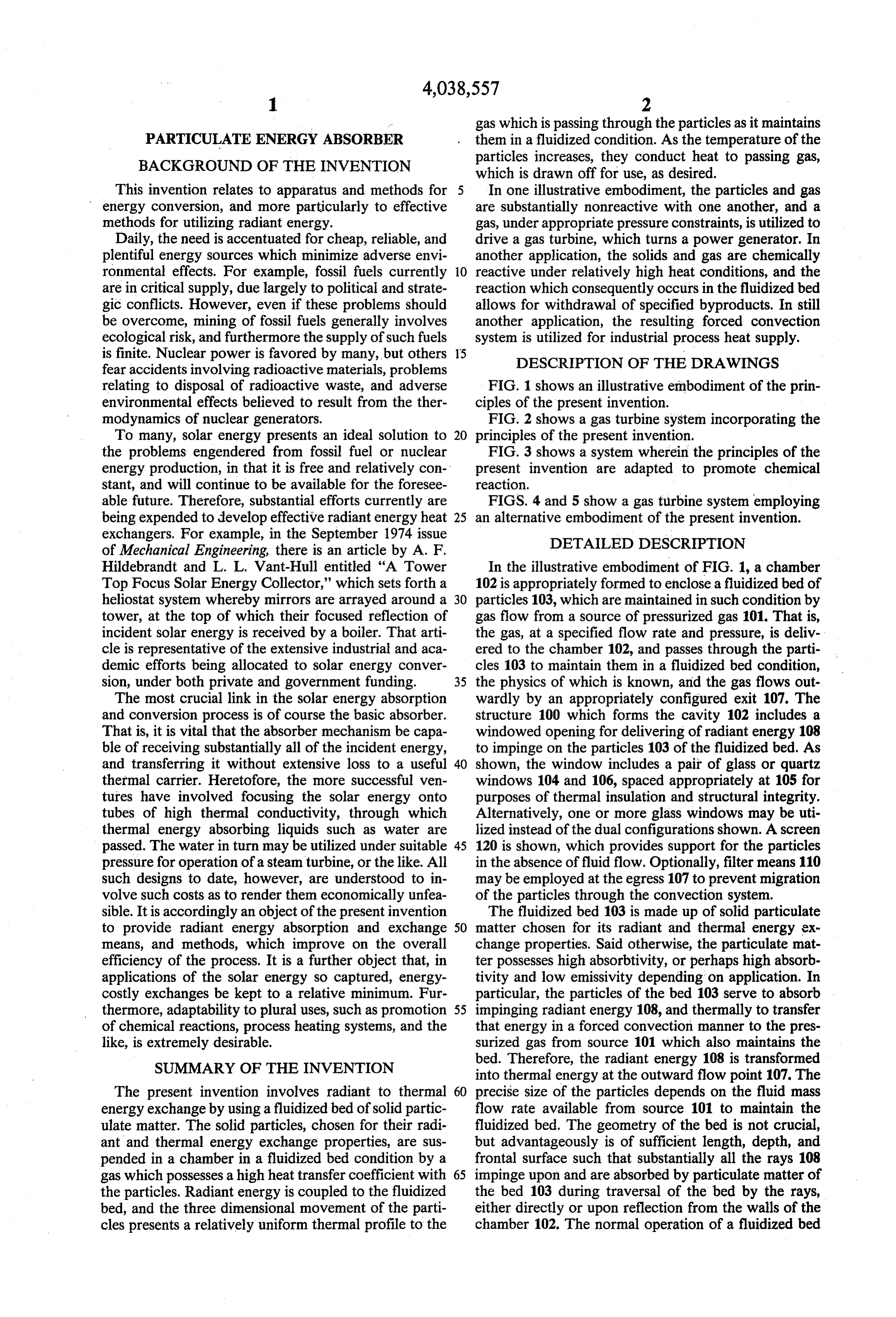
PARTICULATE ENERGY ABSORBER them in a fluidized condition. As the temperature of the BACKGROUND OF THE INVENTION particles increases, they conduct heat to passing gas, which is drawn off for use, as desired.
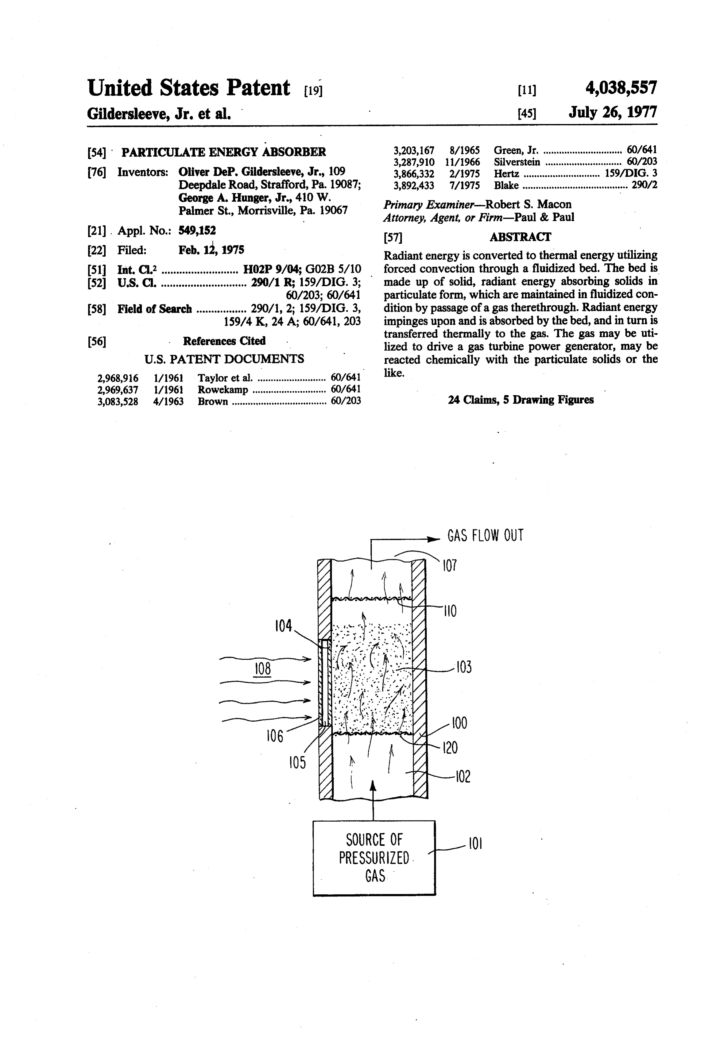
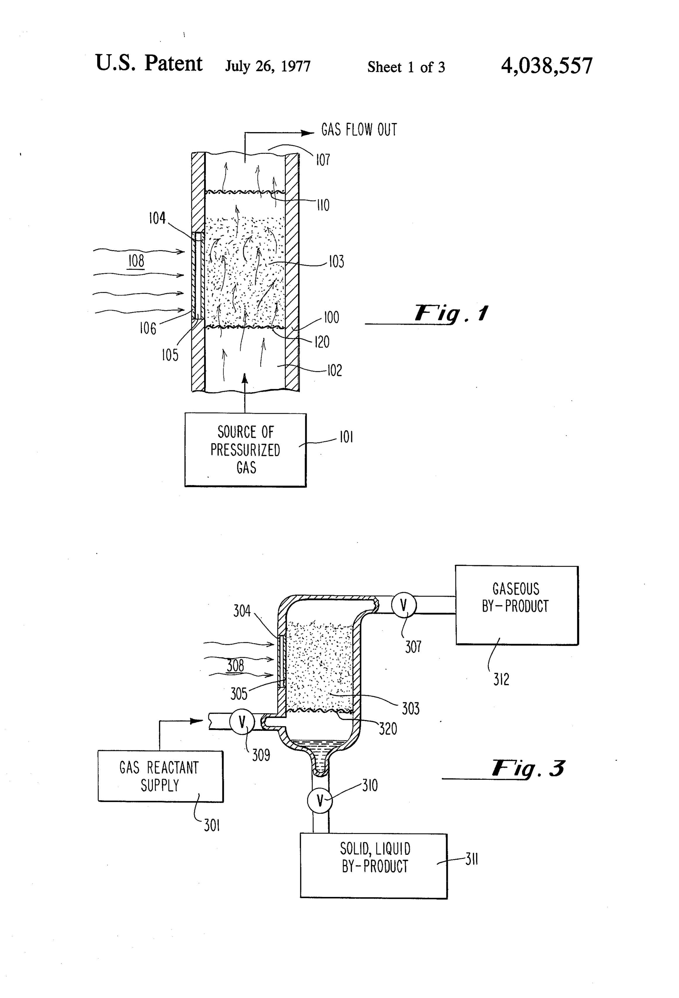
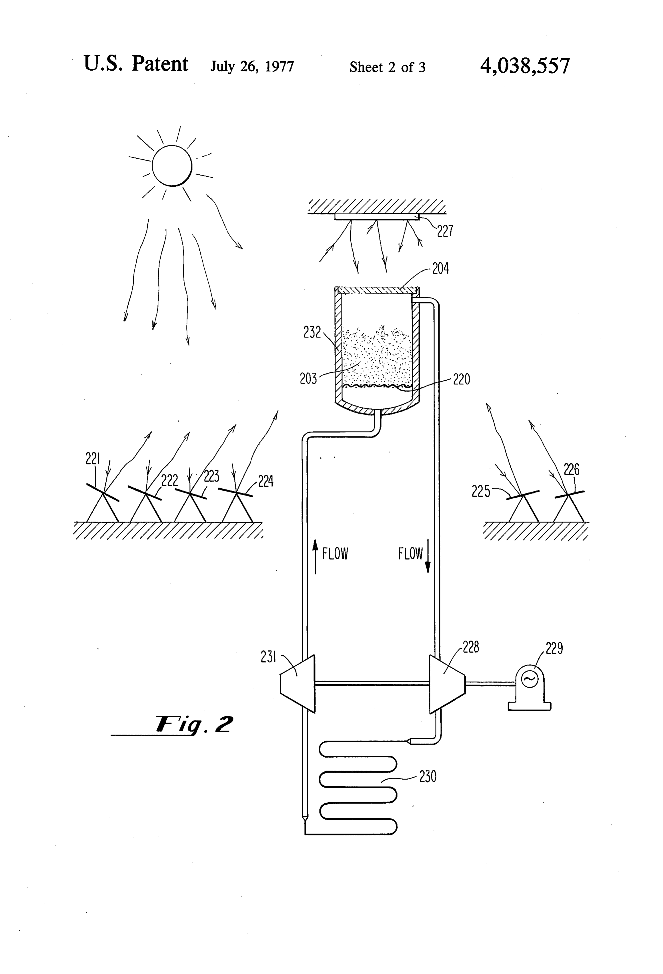
This invention relates to apparatus and methods for 5 In one illustrative embodiment, the particles and gas energy conversion, and more particularly to effective are substantially nonreactive with one another, and a methods for utilizing radiant energy. gas, under appropriate pressure constraints, is utilized to Daily, the need is accentuated for cheap, reliable, and drive a gas turbine, which turns a power generator. In plentiful energy sources which minimize adverse envi another application, the solids and gas are chemically ronmental effects. For example, fossil fuels currently 10 reactive under relatively high heat conditions, and the are in critical supply, due largely to political and strate reaction which consequently occurs in the fluidized bed gic conflicts. However, even if these problems should allows for withdrawal of specified byproducts. In still be overcome, mining of fossil fuels generally involves another application, the resulting forced convection ecological risk, and furthermore the supply of such fuels system is utilized for industrial process heat supply. is finite. Nuclear power is favored by many, but others 15 DESCRIPTION OF THE DRAWINGS fear accidents involving radioactive materials, problems relating to disposal of radioactive waste, and adverse FIG. 1 shows an illustrative embodiment of the prin environmental effects believed to result from the ther ciples of the present invention. modynamics of nuclear generators. FIG. 2 shows a gas turbine system incorporating the To many, solar energy presents an ideal solution to 20 principles of the present invention. the problems engendered from fossil fuel or nuclear FIG. 3 shows a system wherein the principles of the energy production, in that it is free and relatively con present invention are adapted to promote chemical stant, and will continue to be available for the foresee reaction.
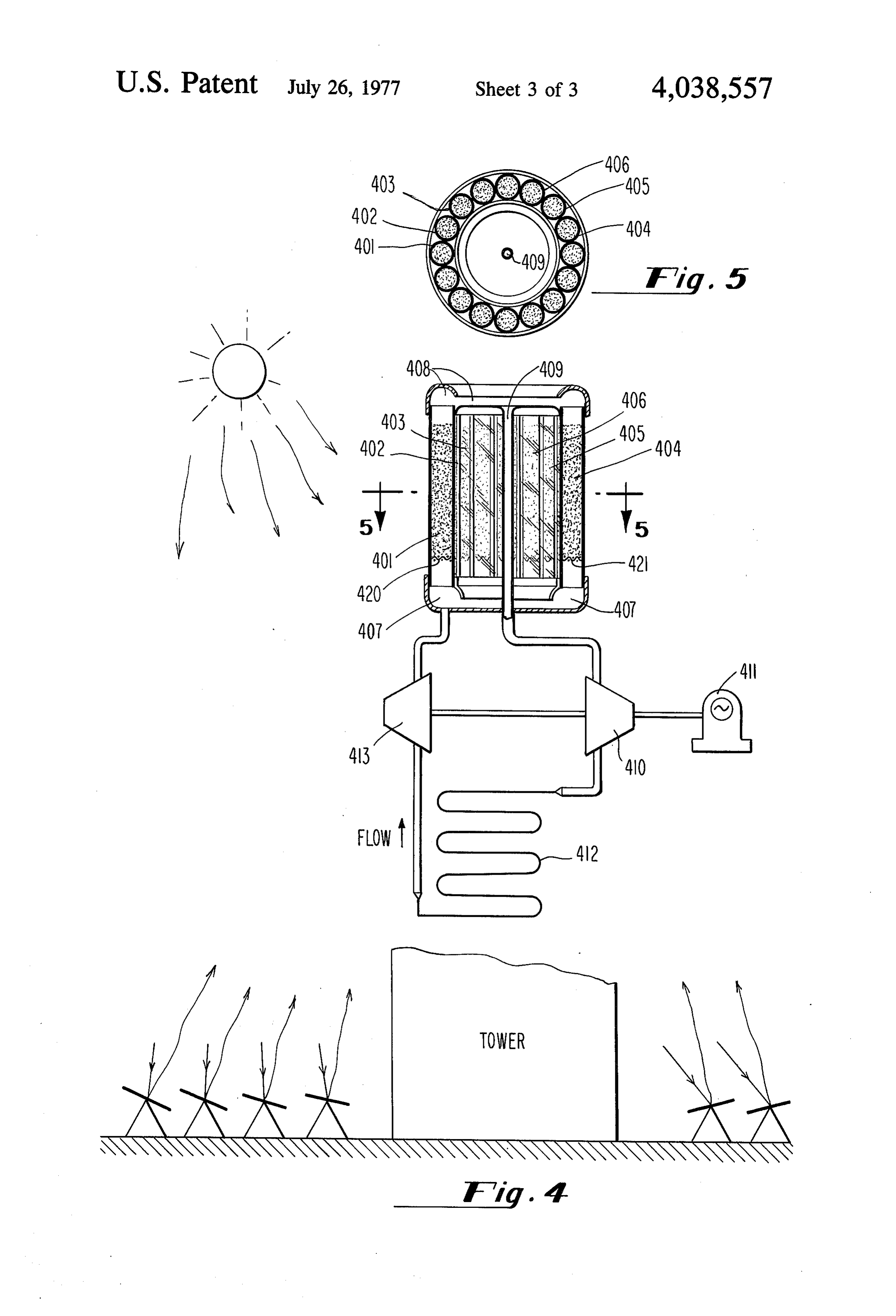
able future. Therefore, substantial efforts currently are FIGS. 4 and 5 show a gas turbine system employing being expended to develop effective radiant energy heat 25 an alternative embodiment of the present invention. exchangers. For example, in the September 1974 issue DETAILED DESCRIPTION of Mechanical Engineering, there is an article by A. F.
Hildebrandt and L. L. Vant-Hull entitled "A Tower In the illustrative embodiment of FIG. 1, a chamber Top Focus Solar Energy Collector,' which sets forth a 102 is appropriately formed to enclose a fluidized bed of heliostat system whereby mirrors are arrayed around a 30 particles 103, which are maintained in such condition by tower, at the top of which their focused reflection of gas flow from a source of pressurized gas 101. That is, incident solar energy is received by a boiler. That arti the gas, at a specified flow rate and pressure, is deliv cle is representative of the extensive industrial and aca ered to the chamber 102, and passes through the parti demic efforts being allocated to solar energy conver cles 103 to maintain them in a fluidized bed condition, sion, under both private and government funding. 35 the physics of which is known, and the gas flows out The most crucial link in the solar energy absorption wardly by an appropriately configured exit 107. The and conversion process is of course the basic absorber. structure 100 which forms the cavity 102 includes a That is, it is vital that the absorber mechanism be capa windowed opening for delivering of radiant energy 108 ble of receiving substantially all of the incident energy, to impinge on the particles 103 of the fluidized bed. As and transferring it without extensive loss to a useful 40 shown, the window includes a pair of glass or quartz thermal carrier. Heretofore, the more successful ven windows 104 and 106, spaced appropriately at 105 for tures have involved focusing the solar energy onto purposes of thermal insulation and structural integrity. tubes of high thermal conductivity, through which Alternatively, one or more glass windows may be uti thermal energy absorbing liquids such as water are lized instead of the dual configurations shown. A screen passed. The water in turn may be utilized under suitable 45 120 is shown, which provides support for the particles pressure for operation of a steam turbine, or the like. All in the absence of fluid flow. Optionally, filter means 110 such designs to date, however, are understood to in may be employed at the egress 107 to prevent migration volve such costs as to render them economically unfea of the particles through the convection system. sible. It is accordingly an object of the present invention The fluidized bed 103 is made up of solid particulate to provide radiant energy absorption and exchange 50 matter chosen for its radiant and thermal energy ex means, and methods, which improve on the overall change properties. Said otherwise, the particulate mat efficiency of the process. It is a further object that, in ter possesses high absorbtivity, or perhaps high absorb applications of the solar energy so captured, energy tivity and low emissivity depending on application. In costly exchanges be kept to a relative minimum. Fur particular, the particles of the bed 103 serve to absorb thermore, adaptability to plural uses, such as promotion 55 impinging radiant energy 108, and thermally to transfer of chemical reactions, process heating systems, and the that energy in a forced convection manner to the pres like, is extremely desirable. surized gas from source 101 which also maintains the SUMMARY OF THE INVENTION bed. Therefore, the radiant energy 108 is transformed into thermal energy at the outward flow point 107. The
The present invention involves radiant to thermal 60 precise size of the particles depends on the fluid mass energy exchange by using a fluidized bed of solid partic flow rate available from source 101 to maintain the ulate matter. The solid particles, chosen for their radi fluidized bed. The geometry of the bed is not crucial, ant and thermal energy exchange properties, are sus but advantageously is of sufficient length, depth, and pended in a chamber in a fluidized bed condition by a frontal surface such that substantially all the rays 108 gas which possesses a high heat transfer coefficient with 65 impinge upon and are absorbed by particulate matter of the particles. Radiant energy is coupled to the fluidized the bed 103 during traversal of the bed by the rays, bed, and the three dimensional movement of the parti either directly or upon reflection from the walls of the cles presents a relatively uniform thermal profile to the chamber 102. The normal operation of a fluidized bed
Page 6
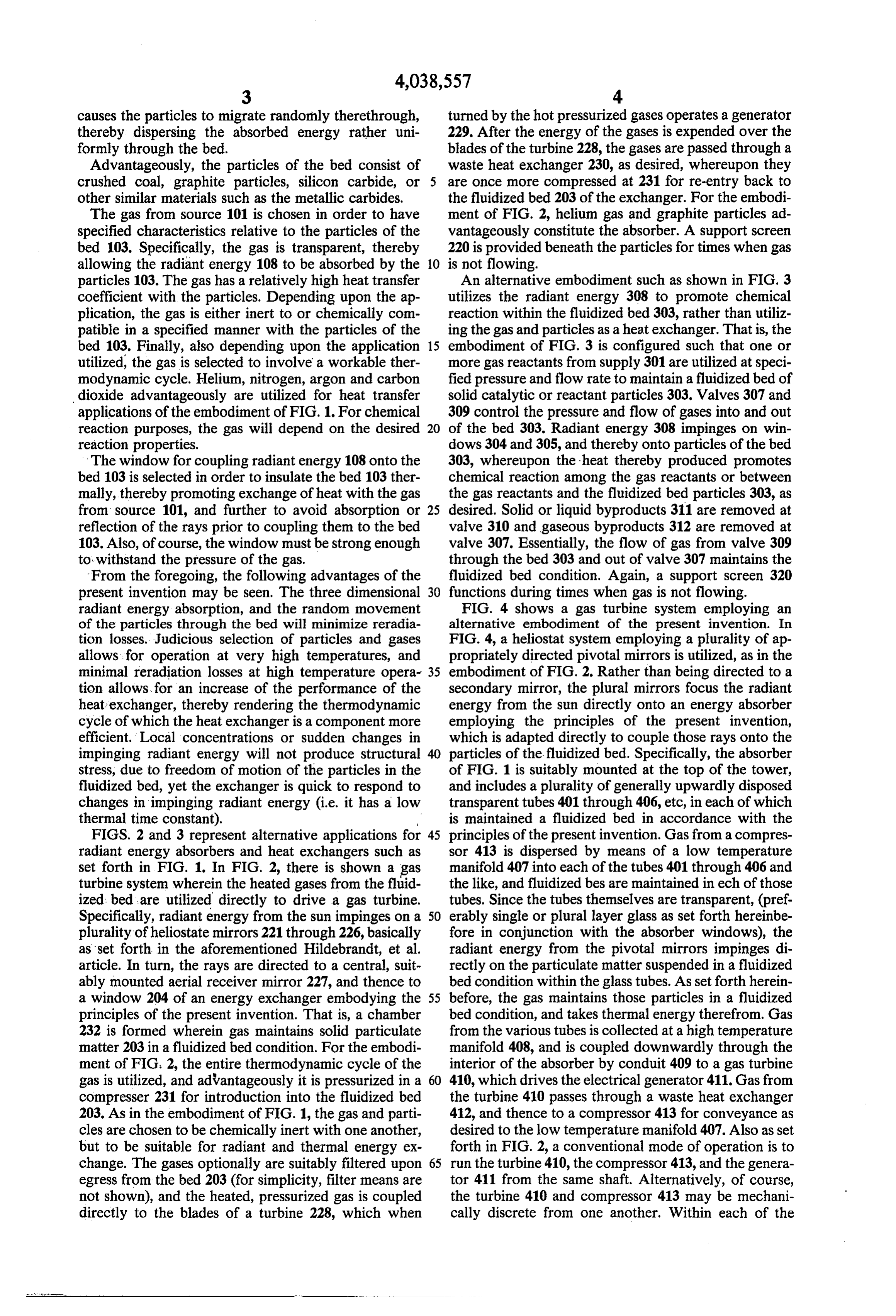
causes the particles to migrate randomly therethrough, turned by the hot pressurized gases operates a generator thereby dispersing the absorbed energy rather uni 229. After the energy of the gases is expended over the formly through the bed. blades of the turbine 228, the gases are passed through a Advantageously, the particles of the bed consist of waste heat exchanger 230, as desired, whereupon they crushed coal, graphite particles, silicon carbide, or 5 are once more compressed at 231 for re-entry back to other similar materials such as the metallic carbides. the fluidized bed 203 of the exchanger. For the embodi The gas from source 101 is chosen in order to have ment of FIG. 2, helium gas and graphite particles ad specified characteristics relative to the particles of the vantageously constitute the absorber. A support screen bed 103. Specifically, the gas is transparent, thereby 220 is provided beneath the particles for times when gas allowing the radiant energy 108 to be absorbed by the 10 is not flowing.
particles 103. The gas has a relatively high heat transfer An alternative embodiment such as shown in FIG. 3 coefficient with the particles. Depending upon the ap utilizes the radiant energy 308 to promote chemical plication, the gas is either inert to or chemically com reaction within the fluidized bed 303, rather than utiliz patible in a specified manner with the particles of the ing the gas and particles as a heat exchanger. That is, the bed 103. Finally, also depending upon the application 15 embodiment of FIG. 3 is configured such that one or utilized, the gas is selected to involve a workable ther more gas reactants from supply 301 are utilized at speci modynamic cycle. Helium, nitrogen, argon and carbon fied pressure and flow rate to maintain a fluidized bed of dioxide advantageously are utilized for heat transfer solid catalytic or reactant particles 303. Valves 307 and applications of the embodiment of FIG. 1. For chemical 309 control the pressure and flow of gases into and out reaction purposes, the gas will depend on the desired 20 of the bed 303. Radiant energy 308 impinges on win reaction properties. dows 304 and 305, and thereby onto particles of the bed The window for coupling radiant energy 108 onto the 303, whereupon the heat thereby produced promotes bed 103 is selected in order to insulate the bed 103 ther chemical reaction among the gas reactants or between mally, thereby promoting exchange of heat with the gas the gas reactants and the fluidized bed particles 303, as from source 101, and further to avoid absorption or 25 desired. Solid or liquid byproducts 311 are removed at reflection of the rays prior to coupling them to the bed valve 310 and gaseous byproducts 312 are removed at 103. Also, of course, the window must be strong enough valve 307. Essentially, the flow of gas from valve 309 to withstand the pressure of the gas. through the bed 303 and out of valve 307 maintains the From the foregoing, the following advantages of the fluidized bed condition. Again, a support screen 320 present invention may be seen. The three dimensional 30 functions during times when gas is not flowing. radiant energy absorption, and the random movement FIG. 4 shows a gas turbine system employing an of the particles through the bed will minimize reradia alternative embodiment of the present invention. In tion losses. Judicious selection of particles and gases FIG. 4, a heliostat system employing a plurality of ap allows: for operation at very high temperatures, and propriately directed pivotal mirrors is utilized, as in the minimal reradiation losses at high temperature opera- 35 embodiment of FIG. 2. Rather than being directed to a tion allows for an increase of the performance of the secondary mirror, the plural mirrors focus the radiant heat exchanger, thereby rendering the thermodynamic energy from the sun directly onto an energy absorber cycle of which the heat exchanger is a component more employing the principles of the present invention, efficient. Local concentrations or sudden changes in which is adapted directly to couple those rays onto the impinging radiant energy will not produce structural 40 particles of the fluidized bed. Specifically, the absorber stress, due to freedom of motion of the particles in the of FIG. 1 is suitably mounted at the top of the tower, fluidized bed, yet the exchanger is quick to respond to and includes a plurality of generally upwardly disposed changes in impinging radiant energy (i.e. it has a low transparent tubes 401 through 406, etc, in each of which thermal time constant). is maintained a fluidized bed in accordance with the FIGS. 2 and 3 represent alternative applications for 45 principles of the present invention. Gas from a compres radiant energy absorbers and heat exchangers such as sor 413 is dispersed by means of a low temperature set forth in FIG. 1. In FIG. 2, there is shown a gas the manifold 407 into each of the tubes 401 through 406 and turbine system wherein the heated gases from the fluid like, and fluidized bes are maintained in ech of those ized bed are utilized directly to drive a gas turbine. tubes. Since the tubes themselves are transparent, (pref. Specifically, radiant energy from the sun impinges on a 50 erably single or plural layer glass as set forth hereinbe plurality of heliostate mirrors 221 through 226, basically fore in conjunction with the absorber windows), the as set forth in the aforementioned Hildebrandt, et al. radiant energy from the pivotal mirrors impinges di article. In turn, the rays are directed to a central, suit rectly on the particulate matter suspended in a fluidized ably mounted aerial receiver mirror 227, and thence to bed condition within the glass tubes. As set forth herein a window 204 of an energy exchanger embodying the 55 before, the gas maintains those particles in a fluidized principles of the present invention. That is, a chamber bed condition, and takes thermal energy therefrom. Gas 232 is formed wherein gas maintains solid particulate from the various tubes is collected at a high temperature matter 203 in a fluidized bed condition. For the embodi manifold 408, and is coupled downwardly through the ment of FIG. 2, the entire thermodynamic cycle of the interior of the absorber by conduit 409 to a gas turbine gas is utilized, and advantageously it is pressurized in a 60 410, which drives the electrical generator 411. Gas from compresser 231 for introduction into the fluidized bed the turbine 410 passes through a waste heat exchanger 203. As in the embodiment of FIG. 1, the gas and parti 412, and thence to a compressor 413 for conveyance as cles are chosen to be chemically inert with one another, desired to the low temperature manifold 407. Also asset but to be suitable for radiant and thermal energy ex forth in FIG. 2, a conventional mode of operation is to change. The gases optionally are suitably filtered upon 65 run the turbine 410, the compressor 413, and the genera egress from the bed 203 (for simplicity, filter means are tor 411 from the same shaft. Alternatively, of course, not shown), and the heated, pressurized gas is coupled the turbine 410 and compressor 413 may be mechani directly to the blades of a turbine 228, which when cally discrete from one another. Within each of the
Page 7
tubes 401 through 406 and the like, screen such as 420 -continued and 421 are provided for purposes of support of the , 7 4. 25.2 38.1 12.9 particles when the system is not being run, and there 8 4. 25.2 37.1 1.9 fore when gas is not being passed through the particles, 9
The totally transparent nature of the absorber structure 5 of FIG. 4 allows rays which may pass through a given tube without being absorbed either to be absorbed at the The foregoing has been presented as illustrative of the downward central conduit 409, or to be absorbed in principles of the present invention. Numerous other another tube. alternative embodiments and applications will occur to It may therefore be noted that in the embodiment of 10 those of ordinary skill in the art without departure from FIG. 2, the absorber may be located anywhere beneath theWespirit or scope thereof.
the secondary mirror 227, either in the tower or below claim: ', it. In the embodiment of FIG. 4, the absorber itself is 1. Apparatus for converting radiant energy, from a mounted at the top of the tower for direct incidence of specified source to thermal energy comprising: the reflected radiation. While conventionally, a stream 15 a. a housing defining a chamber therein; turbine is quite large and unwieldy, and therefore is b. a predetermined quantity of solid particulate mate conveniently located on the ground, a gas turbine is rial in said chamber, capable of absorbing radiant smaller and lighter in weight. Thus, the gas turbine energy;
could be mounted in the tower to minimize piping re 20 c. atmeans for supplying gas to said particulate material a pressure and rate which suspends said particu quirements. However, such expediencies are design options within the ability of those of ordinary skill in the late material in a fluidized bed condition within said art. - chamber; and . .. . . . . ."
EXAMPLE
d. means for coupling radiant energy to said particu late material while simultaneously maintaining said
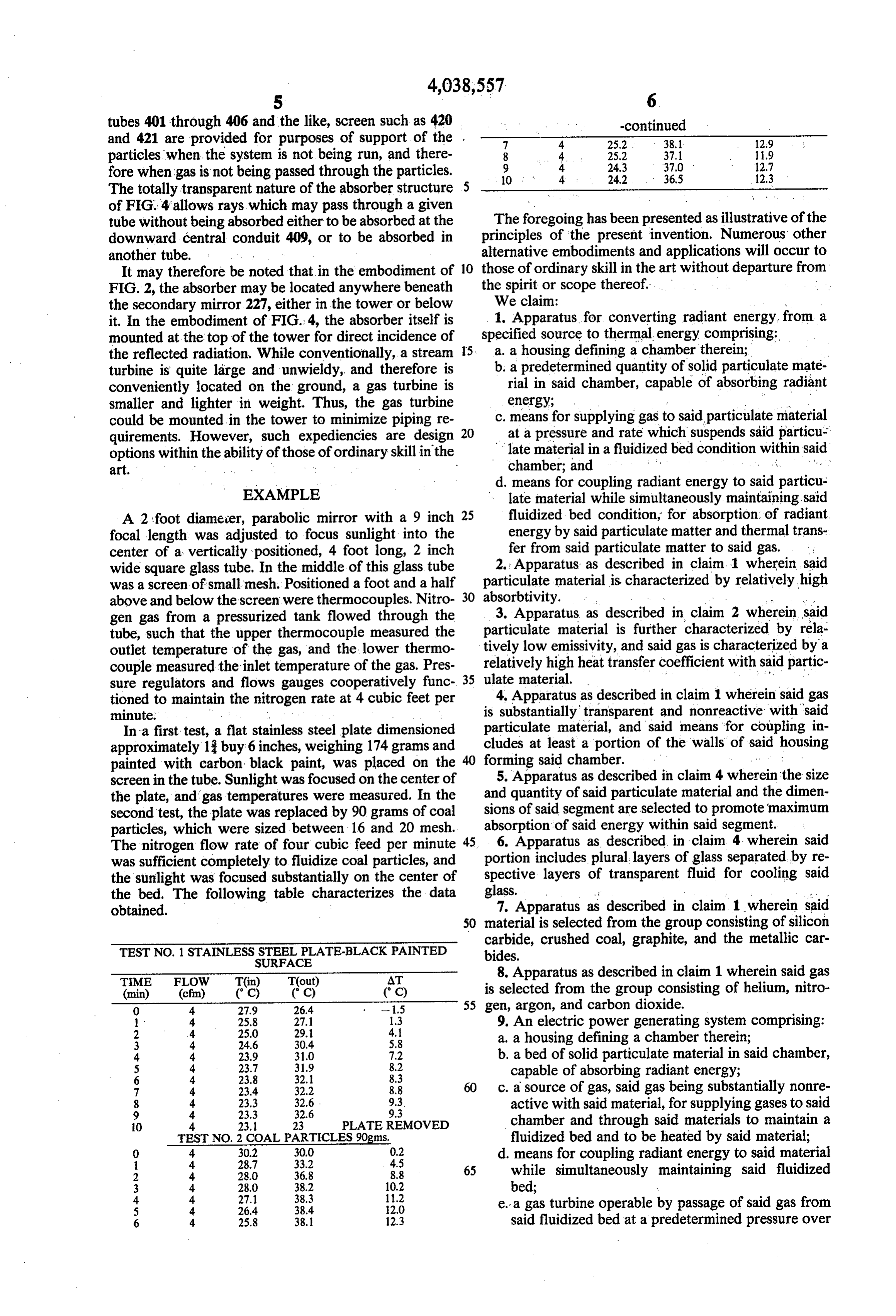
A 2 foot diameter, parabolic mirror with a 9 inch 25 fluidized bed condition, for absorption of radiant focal length was adjusted to focus sunlight into the energy by said particulate matter and thermal trans center of a vertically positioned, 4 foot long, 2 inch fer from said particulate matter to said gas. wide square glass tube. In the middle of this glass tube 2. Apparatus as described in claim 1 wherein said was a screen of small mesh. Positioned a foot and a half particulate material is characterized by relatively high above and below the screen were thermocouples. Nitro 30 absorbtivity.
gen gas from a pressurized tank flowed through the 3. Apparatus as described in claim 2 wherein said tube, such that the upper thermocouple measured the particulate material is further characterized by rela outlet temperature of the gas, and the lower thermo tively low emissivity, and said gas is characterized by a couple measured the inlet temperature of the gas. Pres 35 relatively high heat transfer coefficient with said partic sure regulators and flows gauges cooperatively func ulate material. . . . tioned to maintain the nitrogen rate at 4 cubic feet per is 4.substantially
Apparatus as described in claim 1 wherein said gas transparent and nonreactive with said minute.
In a first test, a flat stainless steel plate dimensioned particulate material, and said means for coupling in approximately 13 buy 6 inches, weighing 174 grams and cludes at least a portion of the walls of said housing painted with carbon black paint, was placed on the 40 forming said chamber. . .. . . . . screen in the tube. Sunlight was focused on the center of 5. Apparatus as described in claim 4 wherein the size the plate, and gas temperatures were measured. In the and quantity of said particulate material and the dimen second test, the plate was replaced by 90 grams of coal sions of said segment are selected to promote maximum particles, which were sized between 16 and 20 mesh. absorption of said energy within said segment. The nitrogen flow rate of four cubic feed per minute 45 portion 6. Apparatus as described in claim. 4 wherein said was sufficient completely to fluidize coal particles, and includes plural layers of glass separated by re the sunlight was focused substantially on the center of spective layers of transparent fluid for cooling said the bed. The following table characterizes the data glass.
obtained. 7. Apparatus as described in claim 1 wherein said 50 material is selected from the group consisting of silicon
TEST NO. 1 STANLESS STEEL PLATE-BLACK PANTED
carbide, crushed coal, graphite, and the metallic car
8. Apparatus as described in claim 1 wherein said gas (min) (cfm) (C) (C) (C) is selected from the group consisting of helium, nitro O 4. 27.9 26.4 - 1.5 55 gen, argon, and carbon dioxide.
9. An electric power generating system comprising:
3 4 24.6 30.4 5.8 a, a housing defining a chamber therein; 4. 4. 23.9 31.0 7.2 b, a bed of solid particulate material in said chamber,
capable of absorbing radiant energy;
7 4. 23.4 32.2 8.8 60 c. a source of gas, said gas being substantially nonre
active with said material, for supplying gases to said 0 4. 23.1 23 PLATE REMOVED chamber and through said materials to maintain a TEST NO. 2 COAL PARTICLES 90gms. fluidized bed and to be heated by said material;
d. means for coupling radiant energy to said material 2 4. 28.0 36.8 8.8 65 while simultaneously maintaining said fluidized 3 4. 28.0 38.2 10.2 bed; y 4 4 27.1 38.3 11.2 e. a gas turbine operable by passage of said gas from
6 4. 25.8 38. 12.3 said fluidized bed at a predetermined pressure over
Page 8
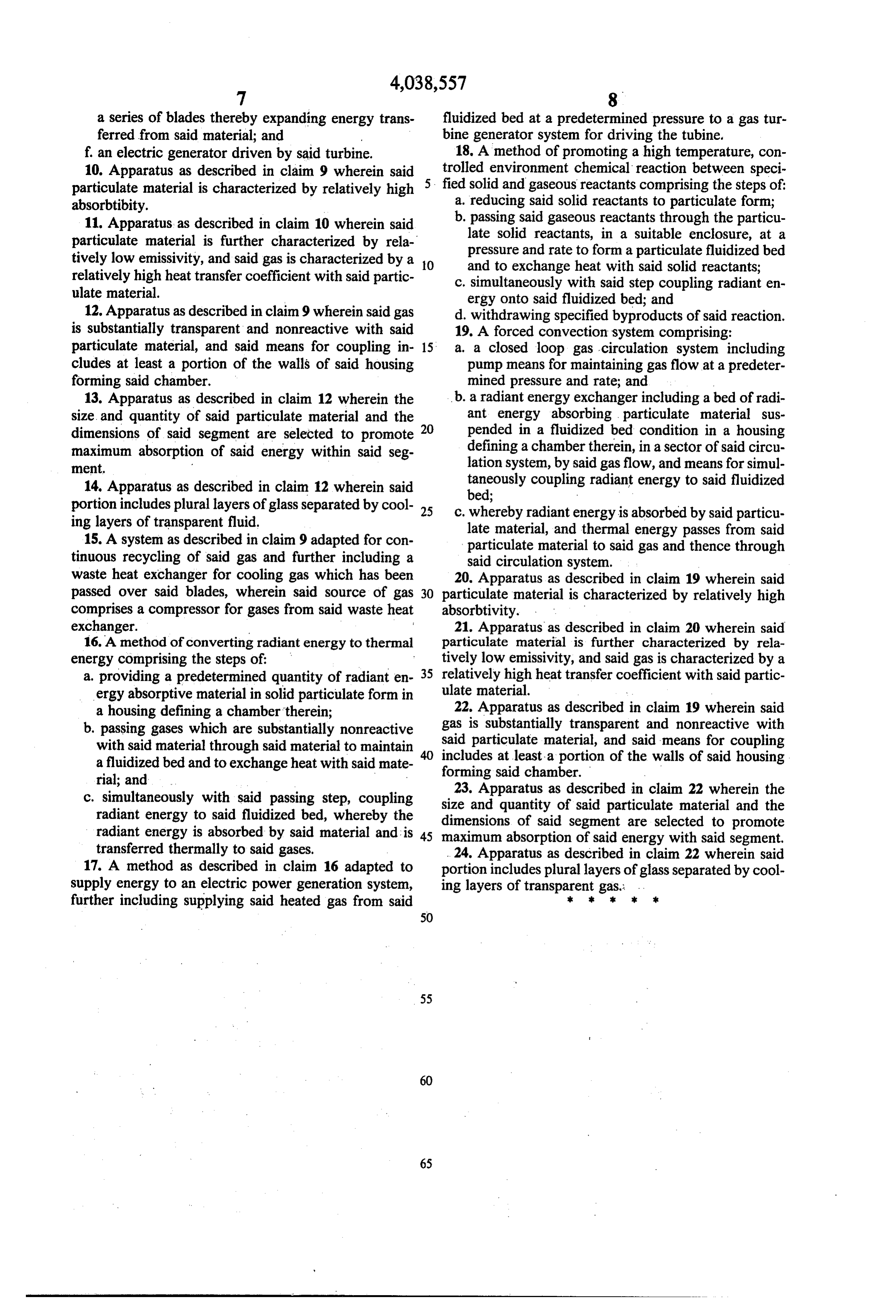
a series of blades thereby expanding energy trans fluidized bed at a predetermined pressure to a gas tur ferred from said material; and bine generator system for driving the tubine. f. an electric generator driven by said turbine. 18. A method of promoting a high temperature, con 10. Apparatus as described in claim 9 wherein said 5. trolled environment chemical reaction between speci particulate material is characterized by relatively high fied solid and gaseous reactants comprising the steps of: absorbtibity. a. reducing said solid reactants to particulate form; 11. Apparatus as described in claim 10 wherein said b. passing said gaseous reactants through the particu particulate material is further characterized by rela late solid reactants, in a suitable enclosure, at a tively low emissivity, and said gas is characterized by a 10 pressure and rate to form a particulate fluidized bed relatively high heat transfer coefficient with said partic and to exchange heat with said solid reactants; ulate material.
c. simultaneously with said step coupling radiant en ergy onto said fluidized bed; and 12. Apparatus as described in claim 9 wherein said gas d. withdrawing specified byproducts of said reaction. is substantially transparent and nonreactive with said 19. A forced convection system comprising: particulate material, and said means for coupling in 15. a. a closed loop gas circulation system including cludes at least a portion of the walls of said housing pump means for maintaining gas flow at a predeter forming said chamber. mined pressure and rate; and 13. Apparatus as described in claim 12 wherein the b. a radiant energy exchanger including a bed of radi size and quantity of said particulate material and the ant energy absorbing particulate material sus dimensions of said segment are selected to promote 20 pended in a fluidized bed condition in a housing maximum absorption of said energy within said seg defining a chamber therein, in a sector of said circu ment. lation system, by said gas flow, and means for simul 14. Apparatus as described in claim 12 wherein said taneously coupling radiant energy to said fluidized portion includes plural layers of glass separated by cool 25 c. bed;
whereby radiant energy is absorbed by said particu ing layers of transparent fluid. late material, and thermal energy passes from said 15. A system as described in claim 9 adapted for con particulate material to said gas and thence through tinuous recycling of said gas and further including a said circulation system. waste heat exchanger for cooling gas which has been 20. Apparatus as described in claim 19 wherein said passed over said blades, wherein said source of gas 30 particulate material is characterized by relatively high comprises a compressor for gases from said waste heat absorbtivity.
exchanger. 21. Apparatus as described in claim 20 wherein said 16. A method of converting radiant energy to thermal particulate material is further characterized by rela energy comprising the steps of: tively low emissivity, and said gas is characterized by a a providing a predetermined quantity of radiant en 35 relatively high heat transfer coefficient with said partic ergy absorptive material in solid particulate form in ulate material.
a housing defining a chambertherein; 22. Apparatus as described in claim 19 wherein said b. passing gases which are substantially nonreactive gas is substantially transparent and nonreactive with said particulate material, and said means for coupling with said material through said material to maintain includes a fluidized bed and to exchange heat with said mate forming said at least a portion of the walls of said housing rial; and chamber.
c. simultaneously with said passing step, coupling size23.and Apparatus as described in claim 22 wherein the radiant energy to said fluidized bed, whereby the dimensionsquantity of said of said particulate material and the segment are selected to promote radiant energy is absorbed by said material and is 45 maximum absorption of said energy with said segment. transferred thermally to said gases, . . 24. Apparatus as described in claim 22 wherein said 17. A method as described in claim 16 adapted to portion includes plural layers of glass separated by cool supply energy to an electric power generation system, ing layers of transparent gas.
further including supplying said heated gas from said k
Provenance
- Collection
- Cited prior art
- Original PDF
- patentimages.storage.googleapis.com →
- Filed
- 1975-02-12
- Pages
- 8
- Method
- pdftotext (the PDF's own text layer) + pdftoppm 300dpi page scans
- Source
- Google Patents bibliographic record
- Granted
- 1977-07-26
- Inventors
- Oliver DeP. Gildersleeve, Jr.; George A. Hunger, Jr.
- Transcribed from
- patentimages.storage.googleapis.com →