patent · US4037650
Thermal storage apparatus
26 July 1977
Page 1 — bibliographic record
United States Patent (19) 11) 4,037,650 Randall 45) July 26, 1977 (54) THERMAL STORAGE APPARATUS Donnelly ............................. 252/67
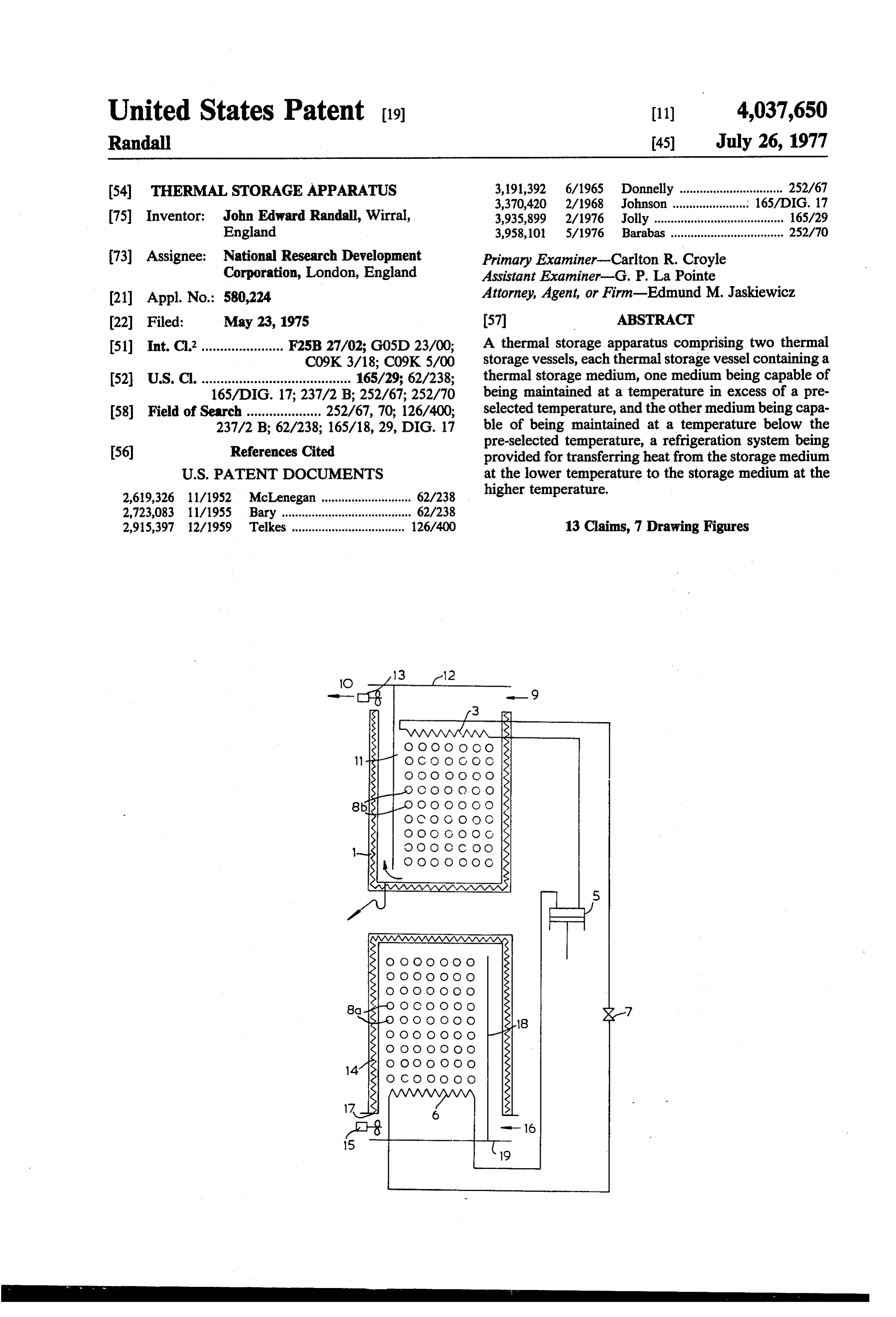
75 Inventor: John Edward Randall, Wirral, 3,935,899 2/1976 Jolly ...... ... 165/29 England 3,958,101 5/1976 Barabas .................................. 252/70 73) Assignee: National Research Development Primary Examiner-Carlton R. Croyle Corporation, London, England Assistant Examiner-G. P. La Pointe (21) Appl. No.: 580,224 Attorney, Agent, or Firm-Edmund M. Jaskiewicz 22 Filed: May 23, 1975 (57) ABSTRACT 51) Int. C.’...................... F25B 27/02; G05D 23/00; A thermal storage apparatus comprising two thermal C09K 3/18; C09K 5/00 storage vessels, each thermal storage vessel containing a 52 U.S. C. ........................................ 165/29; 62/238; thermal storage medium, one medium being capable of 165/DIG. 17; 237/2 B; 252/67; 252/70 being maintained at a temperature in excess of a pre 58) Field of Search .................... 252/67, 70; 126/400; selected temperature, and the other medium being capa 237/2 B; 62/238; 165/18, 29, DIG. 17 ble of being maintained at a temperature below the pre-selected temperature, a refrigeration system being 56) References Cited provided for transferring heat from the storage medium
2,619,326 11/1952 McLenegan ........................... 62/238 higher temperature.
2,915,397 2/1959 Telkes .................................. 126/400 13 Claims, 7 Drawing Figures
MMYYYYY
Page 2
Drawing sheet — no readable text.
Page 3
Drawing sheet — no readable text.
Page 4
Drawing sheet — no readable text.
Page 5
Drawing sheet — no readable text.
Page 6
Drawing sheet — no readable text.
Page 7
Drawing sheet — no readable text.
Page 8
Drawing sheet — no readable text.
Page 9
In the U.S. Pat. No. 3,262,493, a thermal storage ap
THERMAL STORAGE APPARATUS paratus having two thermal stores is disclosed. One of the stores is used for storing heat at a temperature in
The present invention relates to thermal storage appa excess of the temperature at which it is desired to main ratuses and, more particularly, to thermal storage appa tain the interior of a space, such as the interior of a ratuses having two thermal storage vessels which are building, whilst the other store stores heat at a tempera adapted to be maintained at different temperatures, the ture below the ambient temperature of the space. In heat stored in either of these two vessels being transfer such a system, heat is collected from the atmosphere by able to the other vessel. means of solar cells. This heat is transferred to the store Certain types of thermal storage apparatus have been O for high temperature heat and stored therein. This known for some time. Thus, for example, electrical stored heat can then be used at a convenient time for storage heaters are known. Such heaters have been heating the space. When the ambient external tempera designed primarily for markets in which electricity is ture drops, the stored heat is fed from the store into the obtainable on a two-tier tariff. The storage heater is room. To cool the room, heat is collected from the supplied with electricity when the cheaper tariff is in 15 room, generally by a heat transfer medium, and is col operation. The electrical energy supplied to the heater lected in a cold store. As and when desired, this heat is is converted into heat energy and is stored. Ideally, this rejected from the cold store to the external atmosphere. stored heat is used for space heating when the dearer Alternatively, for example at night, the external atmo electricity tariff is in operation. Thus, such heaters are sphere may be allowed to cool the cold store. Since the generally supplied with electricity overnight and used 20 cold store is now colder than the room, heat can be for space heating during the day. However, an appara allowed to flow naturally from the room to the cold tus of this type has the disadvantage that it can only be store, thereby cooling the room. It will be readily ap used for heating purposes. It is not possible to use the parent that the cold store can be used for cooling a apparatus to cool a room. room during a hot period, for example during summer Attempts have been made to overcome this problem. 25 months.
Thus, in U.S. Pat. No. 3,236,294, a system capable of parativelyThe low cold store may be allowed to reach a com temperature when the external tempera producing, at different times, both heating and cooling ture is low. Depending is described. This system comprises a heat storage bin in cold store may be used asupon its storage capacity, the the form of a water drum surrounded by rocks. The during a heat period. The thermalfor a dump heat from a room storage apparatus of drum and the rocks are not thermally insulated from 30 this United States specification differs one another, and so cannot be regarded as two separate closed in U.S. Pat. No. 3,236,294 in thatfrom that dis stores. The heat storage bin can be used for storing heat systems are provided for heating and cooling.separate two
How at any desired temperature. Thus, if such a system is ever, the two systems are substantially independent of installed in a house, and, the ambient external tempera one another. Accordingly, there is no method of up ture is greater than the temperature at which it is de 35 sired to maintain the interior of the house, heat may be grading heat, that is to say, heat absorbed by the cold extracted from the atmosphere and stored in the storage tively means be store cannot transferred to the hot store. This effec that heat absorbed in the cold store cannot bin. This stored heat can then be used at a later time for heating the interior of the house when the external be used, as and when desired, for heating a room. More over, the thermal storage apparatus disclosed in U.S.
ambient temperature falls. Conversely, if the external ambient temperature is below that of the interior of the isPat.supplied
No. 3,262,493 employs natural heat. The hot store house, the bin can be employed to store low tempera cold store iswith its heat from solar radiation, and the maintained at a low temperature by a low ture heat. This low temperature heat can then be used ambient external for cooling the interior of the house when the external effect obtainable temperature. The heating or cooling using the apparatus described in the ambient temperature rises. Thus, the bin of this system 45 U.S. Pat. No. 3,262,493 can be employed for storing heat at any desired temper ability of operation of thisis therefore restricted. The reli prior art system is very much ature. Such a system has two major disadvantages.
Firstly, the system cannot be used to store heat at two dependent upon the weather pattern in the area in different temperature levels simultaneously. This is which the system is employed being substantially con disadvantageous when the house is in a location in 50 sistent over a period of years. If such a weather pattern which there are large short-term fluctuations in temper does not materialise, problems may well arise in main ature, since the system cannot be used to both heat and taining the room or building at a desired temperature. cool the building within a short period of time. Se Alternatively, very large stores must be employed to condly, when the bin is in use as a cold store, a refrigera ensure that the system can cope with alternating de tion system must be employed to maintain the tempera 55 mands.
ture of the bin at a sufficiently low level. As is well It is therefore an object of the present invention to known, heat is absorbed by a refrigerant in the refriger overcome the difficulties and disadvantages in the two ation circuit, which heat is rejected. This is obviously thermal storage apparatuses described above, and to wasteful. Accordingly, the system disclosed in this make it possible to stabilise the temperature in a room, United States specification can be regarded as a thermal 60 particularly when the temperature range within the storage apparatus which can be used for either space room, under normal circumstances, would otherwise heating or space cooling. The heating and cooling ef. fluctuate considerably on either side of the proposed fects of such a system can therefore be effectively re stabilised temperature. By means of the present inven garded as two independent uses of the same apparatus. tion, it has surprisingly been found that it is possible for Thus, utilising such a system, heat can be extracted from 65 substantially all of the heat absorbed by a cold storage a room and the room is thus cooled. This heat is dis vessel in cooling to be transferred, in a comparatively charged to the external atmosphere and cannot be simple manner, to a hot storage vessel. This heat which stored for re-heating the room when desired. has been transferred can be used at any convenient time.
Page 10
This ability of the system of the present invention to (ortho) phosphate dodecahydrate, sodium carbonate transfer heat from the cold storage vessel to the hot decahydrate, sodium sulphate decahydrate, and a mix storage vessel has numerous advantages. Basically, in ture of hydrated sodium silicate and sodium carbonate known systems, heat is obtained from a source, stored, decahydrate, a first storage vessel, a plurality of con and then utilised when convenient. No conscious at tainers in said first storage vessel, each said container tempt has been made to recycle heat. Thus in a domestic containing the thermal storage medium selected from refrigerator, a refrigerant cools the interior of the refrig the group consisting of water, an aqueous solution of a erator. The heat removed from the refrigerator is salt, a crystallisable salt hydrate and a mixture of crys merely discharged by radiation from conduits at the tallisable salt hydrates, said storage medium in said first back of the refrigerator. No attempt has hitherto been 10 storage vessel having the characteristic of solidifying made to utilise this heat. Similarly, the use of a heat with the evolution of heat at a temperature below a pump is known to transfer heat from a cold source to a preselected temperature, said temperature being below hot source. Thus, for example, it is known to take water the crystallisation temperature or temperatures of said from a river and pass the water through a heat pump. storage medium in said second storage vessel, and a The heat extracted therefrom can be used to heat a 15 refrigeration circuit containing a refrigerant, said refrig building. In so doing, the temperature of the water is eration circuit comprising, in series, an evaporator, a lowered. The cooled water is then returned to the river compressor, a pressure reduction device and a heat despite the fact that it could be used to cool the building exchanger, said heat exchanger being located within if the internal temperature thereof rose above a certain said second storage vessel and said evaporator being level. 20
However, by using the apparatus of the present inven located within said first storage vessel. The term "crys tallisable' as used throughout this specification must be tion, heat can be recycled. Suppose, for example, the construed as system of the present invention is being used to cool a tallised form. also including the salt hydrate in its crys room. Air is passed through the storage vessel which is By providing a refrigeration system, heat which is at the lower temperature. In so doing, the temperature 25 absorbed in the first or cold storage vessel when a room of this cold store would tend to rise. However, by utilis is being cooled ing a refrigeration system, the heat absorbed in the cold the second or hotbystorage the apparatus can be transferred to store can be transferred to the storage vessel which is at time for heating the room.vessel By for use at a convenient using both a hot storage the higher temperature, that is to say, the hot store. The vessel and a cold storage vessel and a refrigeration hot store can store this heat, which can then be utilised 30 system the refrigeration system can be operated contin to heat the room as and when desired. Conversely, uously, even though heating and cooling are required when this heat is being used to heat the room, the tem only intermittently.
perature of the hot store would tend to drop. However, It will be readily apparent to those skilled in the art the hot store absorbs heat from the refrigerant. The thus that cooled refrigerant thus cools the cold store, which can 35 whichthere can are several advantages in using a heat pump be operated continuously instead of intermit then be utilised for cooling the room when desired. It tently. Thus, for example, a room which faces the sun can therefore be seen that heat can be recycled. during a major portion of the day may receive as much Moreover, by the provision of two separate stores, heating or cooling are available at substantially any as ten kilowatts of solar radiation. Obviously, the tem time. Thus, the system of the present invention can be 40 perature within the room would, under normal circum stances, rise considerably. To maintain the temperature utilised even in conditions where short-term fluctua tions of weather take place. of the room at a desired level, some form of refrigera Whilst both refrigeration systems and thermal storage tion system is required to remove the heat produced by apparatuses are known, the system of the present inven tion, the solar radiation. In the absence of the present inven tion utilises seemingly simple combination of these two 45 this normally entails the use of an air-conditioning integers to provide a thermal storage system which system embodying a refrigeration system. At the time produces advantages which could not be foreseen. when the heating effect produced by the solar radiation Thus, heat may be recycled. This is a feature which is of is at a maximum, this refrigeration system may need a paramount importance in the current energy shortage. power input rated as highly as 3 kilowatts. However, Moreover, the system of the present invention still per 50 the full capacity of the refrigeration system is only uti mits the use of natural heating or cooling of the stores. lised for a brief period of time, of the order of perhaps According to the present invention, there is provided half to one hour. Obviously, therefore, the refrigeration a thermal storage apparatus comprising a first thermal system will be working at less than its full capacity for storage vessel containing a first thermal storage medium much of the day. It is well known that practical difficul which is capable of being maintained at a temperature 55 ties arise in operating a refrigeration system at reduced below a pre-selected temperature, a second thermal capacity, unless the system is very refined, and there storage vessel containing a second thermal storage me fore very expensive. With the present invention, how dium, which is capable of being maintained at a temper , ever, by using two thermal storage vessels, one at a high ature above said pre-selected temperature, and a refrig temperature and one at a low temperature, the maxi eration system for transferring heat from said first stor mum power input required in the same ambient condi age vessel to said second storage vessel. tions can be reduced to something of the order of 0.5 In a preferred embodiment of the present invention, kilowatts. Obviously, a refrigeration system having a the second thermal storage vessel contains a plurality of maximum power input of 0.5 kilowatts is smaller, containers each containing the thermal storage medium cheaper and quieter in operation than one having a in the form of at least one crystallisable salt hydrate 65 maximum input of 3.0 kilowatts. Moreover, with the selected from the group consisting of trisodium (ortho) present invention all of the heat absorbed by the refrig phosphate dodecahydrate, a mixture of trisodium (or eration system can be used at a later time, as and when tho) phosphate dodecahydrate and disodium hydrogen convenient.
Page 11
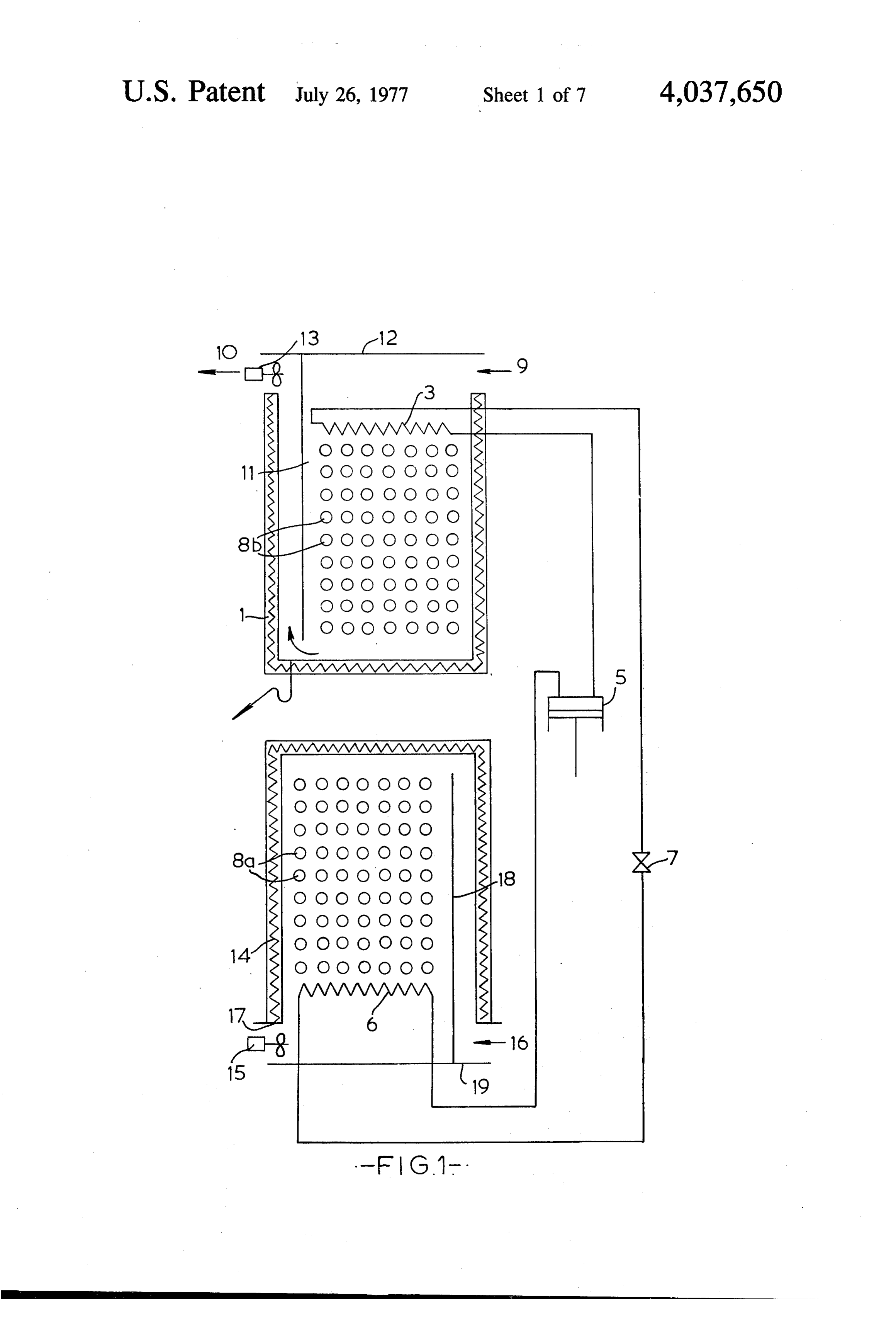
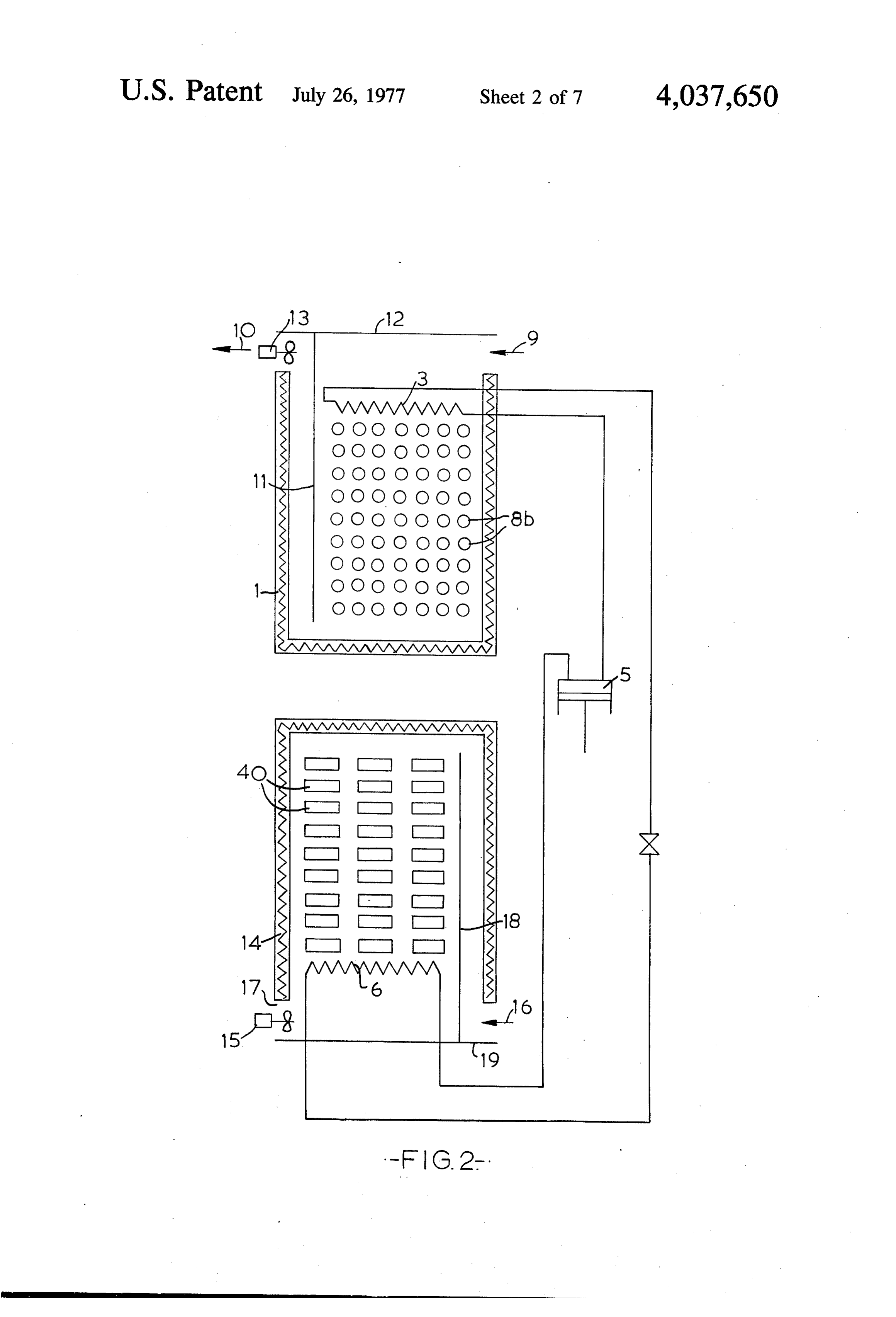
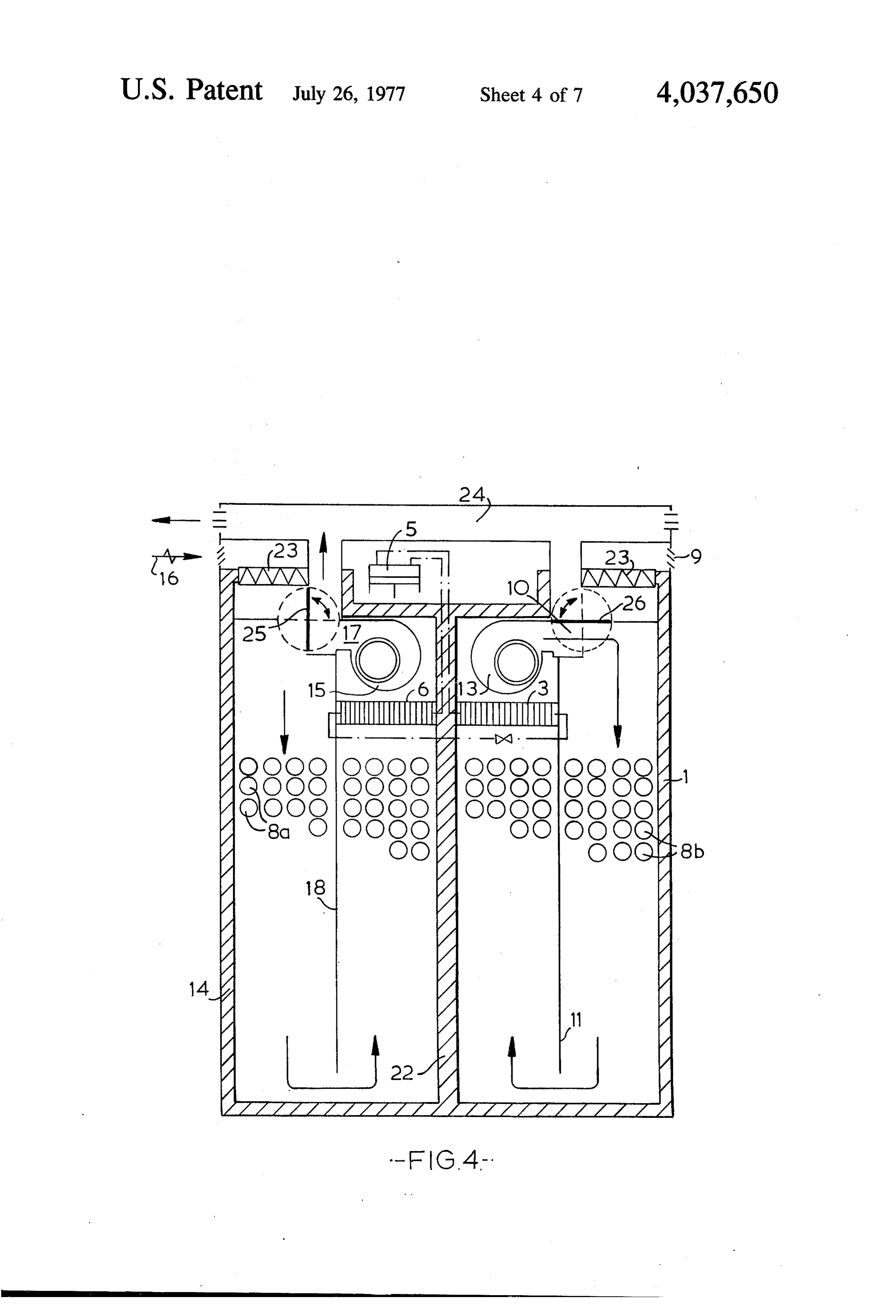
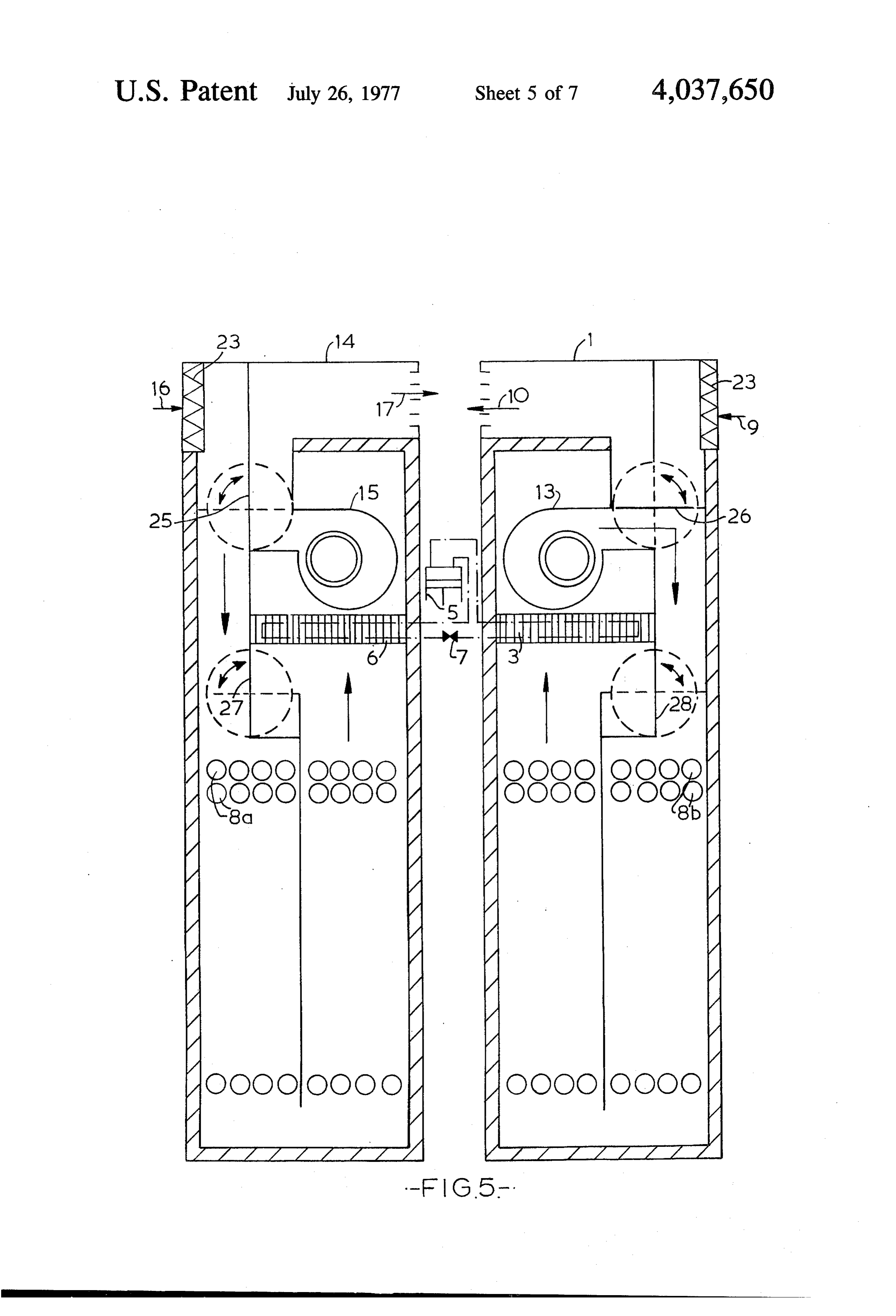
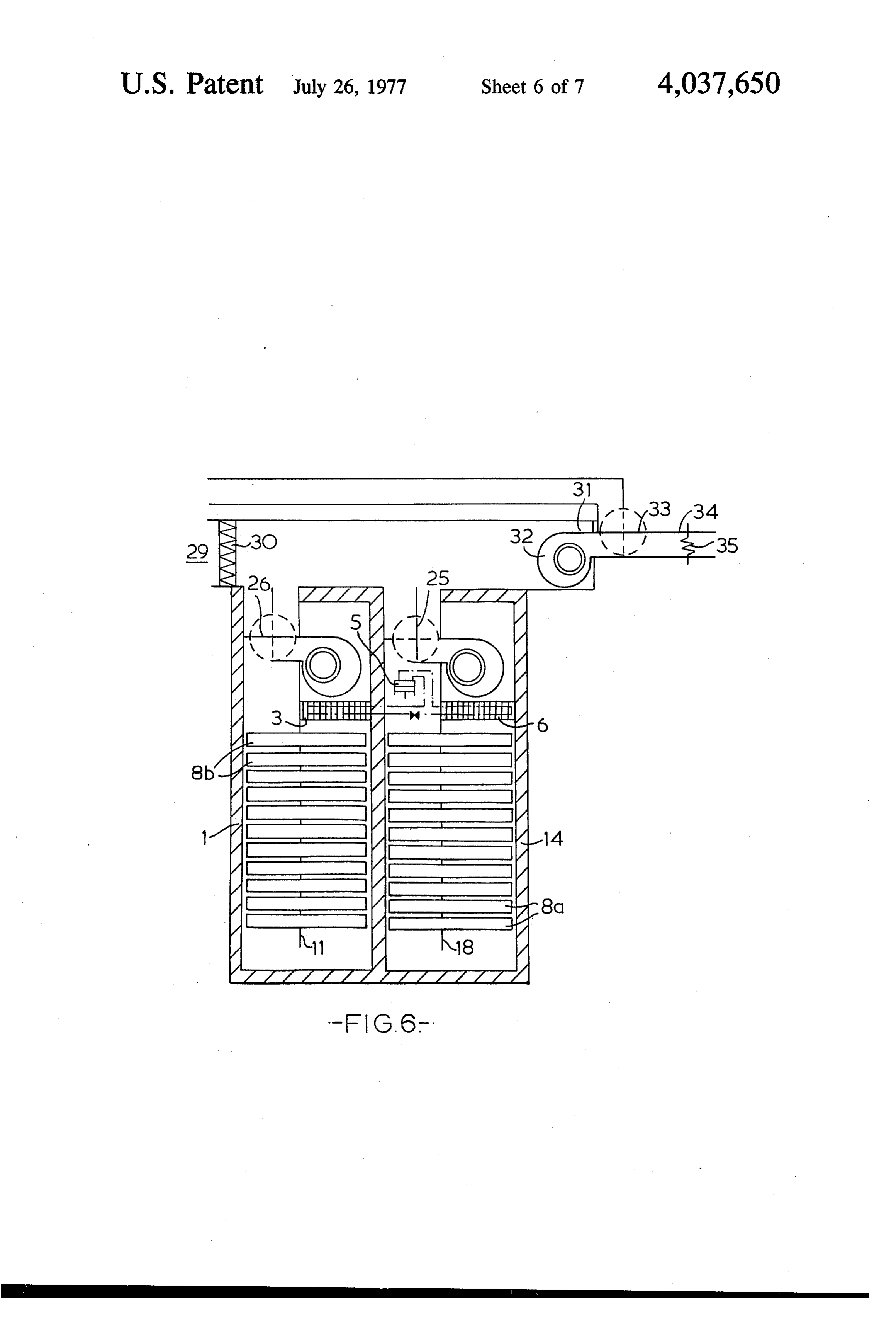
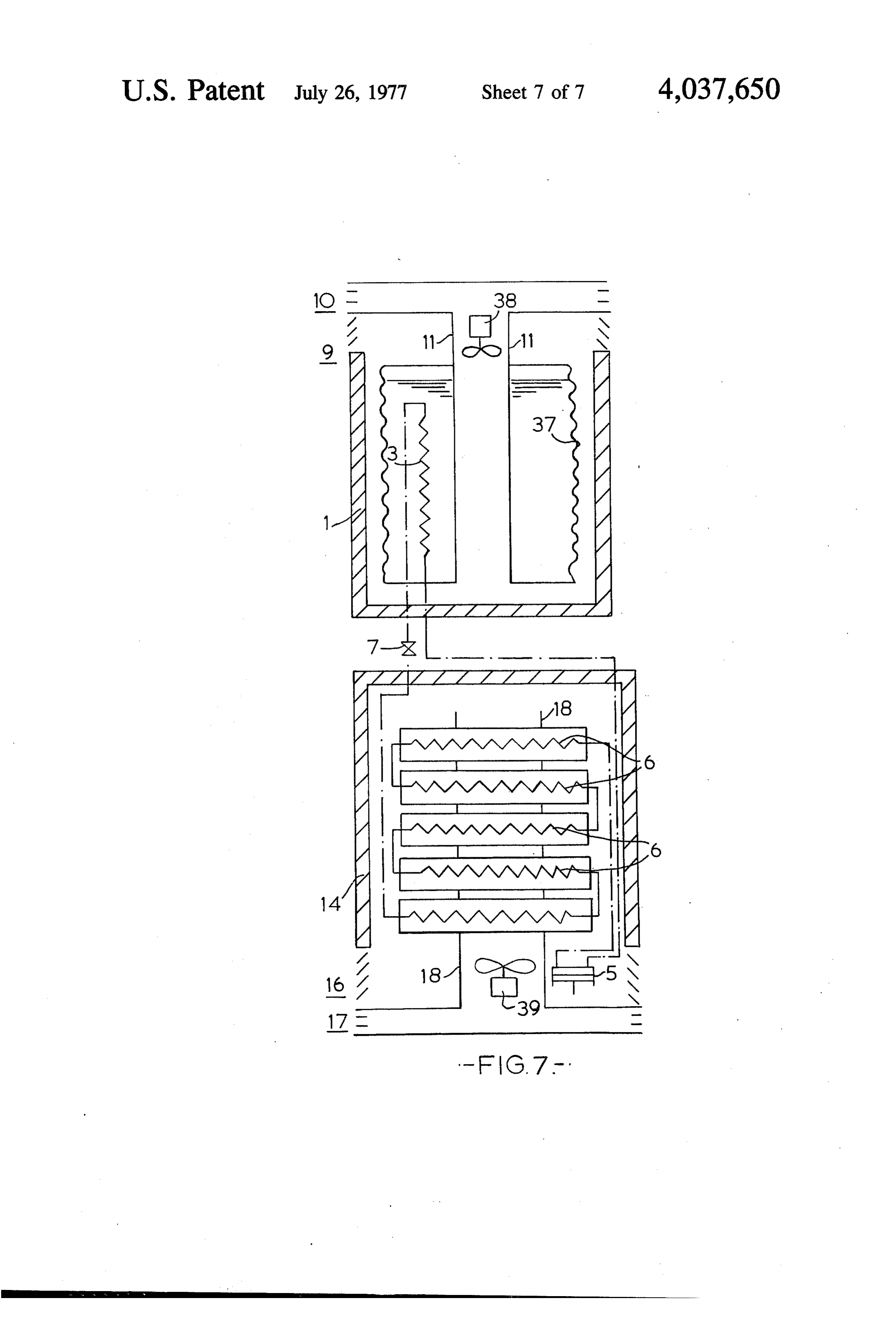
The high temperature thermal store may contain any erably of the vapour compression type, but may alterna suitable medium which can be heated easily but which tively be of the thermo-electric type (operating on the cools only slowly under natural conditions. Accord Peltier principle) or of the absorption type. ingly, as is well known, the criteria for thermal storage Embodiments of the invention will be further de materials such as that contained in the hot store are that 5 scribed by way of example, with reference to the ac (a) it has a high specific heat capacity or latent heat (b) companying drawings in which:- a high density (to give a low volume) and (c) a high FIGS. 1 and 2 each show a schematic view of a ther thermal conductivity. In a particularly preferable em mal storage apparatus in accordance with the present bodiment of the present invention, the medium con invention, the two figrues showing substantially identi tained in the first storage vessel is a crystallisable salt 10 cal systems, with the sole exception of the contents of hydrate. It is well known that when most salt hydrates the storage vessels;
crystallise, heat is evolved. It will be readily apparent FIG. 3 is a schematic longitudinal section through a that it would be advantageous to use this heat of crystal storage vessel forming part of athermal storage appara lisation. It has been found particularly advantageous if tus in accordance with the present invention; the salt hydrate is selected from the group consisting of 15 FIG. 4 is a schematic longitudinal section through a sodium carbonate heptahydrate, sodium carbonate modified thermal storage apparatus in accordance with decahydrate, sodium sulphate decahydrate, disodium the present invention; and hydrogen phosphate heptahydrate, disodium hydrogen FIG. 5 is a schematic longitudinal section through a phosphate dodecahydrate, sodium thiosulphate hepta further embodiment of a thermal storage apparatus in hydrate, sodium acetate trihydrate, calcium chloride 20 accordance with the present invention; heptahydrate and trisodium(ortho)phosphate dodeca FIG. 6 is a schematic longitudinal section through a hydrate. Alternatively, mixtures of these compounds thermal storage apparatus similar to that shown in FIG. may be used. 4 but having minor constructional differences relative Similarly, it is advantageous for the cold store to thereto; and contain a freezable liquid. The term "freezable liquid' 25 FIG. 7 is a schematic view of a thermal storage appa as used through this specification is to be construed as ratus similar to that shown in FIGS. 1 and 2 but having also including the liquid when in its frozen or solid state. minor constructional differences relative thereto. Thus, for example, the cold store may contain water. By In FIG. 1, thermal storage apparatus comprises a first using a freezable liquid the latent heat of fusion of the thermal storage vessel 1 within which are located con liquid can be extracted, and transferred to the hot store. 30 tainers 8b. The containers contain a freezable liquid The term "freezable' is intended to encompass crystal which may be water or a suitable crystallisable salt lisable salt hydrates, or mixtures thereof, which crystal hydrate, or mixture of hydrates, which crystallises at a lise at suitably low temperatures. When using such com suitably low temperature or temperatures. For the sake pounds, the heat of crystallisation is extracted, and not of clarity, it will be assumed that the containers 8b con the latent heat of fusion. However, since the latent heat 35 tain water. These containers 8b are sealed. of fusion and the heat of crystallisation are both types of The storage vessel 1 also has an air inlet 9 and an air heat produced when a liquid solidifies, compounds outlet 10. As shown, both the inlet 9 and the outlet 10 which produce such an effect are referred to in this are at the upper end of the storage vessel 1. Between the specification as "freezable liquids'. It has been found inlet 9 and the outlet 10, a baffle 11 is provided. This that a eutectic mixture of salt hydrates, particularly a 40 baffle 11 may advantageously be integrally formed with eutectic mixture of hydrates of sodium sulphate and a cover 12 for the storage vessel. Within the storage ammonium chloride are particularly suitable. Alterna vessel 1, spaces are provided between the containers 8b tively, waterglass may be used as the freezable liquid. to allow air to pass therearound. A fan 13 is provided to Whilst the chemistry of waterglass (sodium silicate) is draw air through the storage vessel 1, the baffle 11 extremely complex, it is believed that this compound 45 preventing air from flowing directly from the inlet 9 to may well form single or mixed hydrate crystals if the the outlet 10 without passing over the containers 8b. waterglass is heated and then cooled. Accordingly, for Also located within the storage vessel 1 is an evapora the purposes of this specification, the term "crystallisa tor 3 forming part of a refrigeration circuit. A refriger ble salt hydrate' is to be interpreted as including water ant fluid flows through the evaporator 3. The evapora glass. If the freezable liquid is water, it may have mixed 50 tor is in series with a compressor 5 and heat exchanger therewith an oil or other water immiscible liquid. A 6. This heat exchanger 6 is located within a second portion of this water-immiscible liquid may be ex storage vessel 14. The second storage vessel 14 is, in tracted, cooled and re-injected into the water. By so essence, extremely similar to the storage vessel 1. The doing, the oil acts as a heat transfer medium and, if containers 8a within the storage vessel 14 contain a sufficiently cold, can act as an initiator for freezing of 55 crystallisable salt hydrate. Alternatively, these contain the water. Alternatively, a polyhydric alcohol such as ers 8a may be filled with a crystallisable salt hydrate ethylene glycolor glycerol or a salt may be added to the plus water.
water. By so doing the water does not freeze hard. This As with the storage vessel 1, a fan 15 is provided to is of importance if the water is in a sealed container draw air through the storage vessel 14. In the storage since the freezing thereof would set up considerable 60 vessel 14, it will be noticed that the air inlet 16 and the expansion force. air outlet 17 are both located at the bottom of the vessel. The thermal storage apparatus in accordance with the A baffle 18, which may be integrally formed with a base present invention may additionally be provided with plate 19 is provided between the inlet 16 and the outlet means for forcing air flow over and/or through one or 17. The purpose of this baffle 18 is to prevent air passing both of the storage vessels. Additionally, one or both 65 directly from the inlet 16 to the outlet 17 without pass storage vessels may in addition be provided with heat ing over the containers 8a, ing means, which heating means may comprise an elec The operation of the illustrated apparatus will now be trical heating element. The refrigeration system is pref described. The storage vessel 1 is maintained at below
Page 12
the desired room temperature and so may be regarded ature than before. The large quantity of air to be cooled as a “cold' store whilst the storage vessel 14 is main may, for example, be extracted from a room which has tained at above the desired room temperature and so been heated by the sun. The ice may also be melted by may be regarded as a 'hot' store. Assuming for the use of an additional heating element.
moment that the compressor 5 is operating, the refriger 5 The arrangement shown in FIG. 2 is virtually identi ant fluid flows through the evaporator 3 in the storage cal to that shown in FIG. 1. The sole difference is that vessel 1. In so doing, the refrigerant fluid extracts heat the hot store 14 contains not a crystallisable salt hydrate from the freezable liquid contained in the containers 8b but refractory bricks. 40. These bricks 40 are stacked located in the storage vessel 1. This causes the freezable one upon the other in rows. It will be readily apparent liquid to freeze and the refrigerant fluid to be heated. 10 that whilst refractory bricks have a high thermal stor The heated refrigerant fluid passes through the com age capacity, only the heat stored in the bricks can be pressor 5, and then through the heat exchanger 6 lo extracted. Unlike the crystallisable salt hydrate, it is cated in the storage vessel 14. obviously not possible to obtain any latent heat of fusion Passage of the refrigerant through heat exchanger 6 or heat of crystallisation from these bricks. Neverthe causes the crystallisable salt hydrates contained in the 15 less, under certain circumstances the use of refractory containers 8a in the storage vessel 14 to become heated. bricks may be more advantageous than utilising a crys The crystallisable hydrates mentioned hereinbefore all tallisable salt hydrate. Thus, if the apparatus is not re have one common characteristic. This characteristic is quired to have an extremely high heat storage density, it that they lose some of their water of crystallisation is easier to manufacture an apparatus using bricks rather when heated, and, on cooling, they recrystallise with than containers of a crystallisable salt hydrate. More the evolution of considerable quantities of heat. Thus, over, refractory bricks may be heated to a higher tem when heated by the refrigerant fluid, the crystallisable perature by an auxiliary heating element. salt hydrates will lose at least some of their water of It will also be recalled that the storage vessel 14 is a crystallisation. hot store, heat being obtained from this store by cooling A pressure reduction device 7 is located, in the refrig 25 the contents of the containers 8a from an elevated tem erant circuit, between the external heat exchanger 6 and perature to their recrystallisation temperature. It is the evaporator 3. therefore extremely desirable to ensure that substan The compressor 5 may be run in dependence upon tially uniform cooling of the containers throughout the load conditions. Thus, it can be run when electricity is hot store takes place. It has been found that if a storage cheap, for example, at night, and then be switched off. 30 vessel has containers located therein, and air is passed Alternatively, it may be run continuously. For the sake over these containers, the containers near the inlet are of example, it will be assumed that the compressor 5 has cooled more rapidly than those near the outlet. This is been run until substantially all of the freezable liquid obviously undesirable since less heat is obtainable, in contained in the containers 8b within the storage vessel practice, from the containers near the outlet. 1 have frozen and all of the crystallisable salt hydrate 35 FIG. 3 shows a design of a storage vessel which is contained in the container 8a located in the storage intended to overcome this disadvantage. For ease of vessel 14 have been heated until they are at a tempera understanding and for the sake of clarity, FIG. 3 will be ture which is above their crystallisation temperature. taken as illustrating the storage vessel 14 shown in FIG. As already indicated, the thermal storage apparatus of 1. However, the design is equally applicable to the stor the present invention can now be used for supplying 40 age vessel 1 shown in that Figure. Thus referring to either heated air or cooled air to a room. Suppose, for FIG. 3, it will be seen that storage vessel 14 is cylindri example, that it is desired to supply heat to the room. cal and is open at one end. The walls of the storage This is done by switching on the fan 15 in the storage vessel are made of a thermally insulating material. In the vessel 14 to draw air over the heated containers 8a and central region of the open end of the storage vessel 14, to supply it to the room. The air flow over the contain 45 there is shown the external heat exchanger 6. The annu ers 8a means that the temperature of the contents of lar space around the heat exchanger 6 constitutes the air these containers 8a will commence to fall. At a certain inlet 16. The side walls of the heat exchanger 6 have temperature, the salt hydrates will begin to recrystallise. extension portions 21 which project into the storage As previously mentioned, when such recrystallisation vessel 14. These extension portions 21 constitute a baf. takes place, relatively large quantities of heat are 50 fle. Within the interior of the storage vessel 14, a plural evolved. The temperature of the containers 8a will ity of containers 8a are provided. These containers 8a remain constant, or fall slowly, until substantially all of extend substantially from the centre of the storage ves the hydrate has recrystallised. Accordingly, heat may sel to the peripheral wall. The containers 8a pass be supplied to the room for a relatively lengthy period through the extension portions 21 into an annular chan of time. 55 nel 21' defined between wall 14 and extension portion If on the other hand, it is desired to cool the room, 21. It will be assumed that the contents of the containers then the fan 13 in the storage vessel 1 is switched on 8a are at a temperature above their crystallisation tem instead of switching on fan 15. The fan 13 causes air to perature. In use, a fan (not shown), causes air to pass flow over the containers 8b within the storage vessel 1. into the inlet 16 and then flow over those outer parts of In so doing, the air will be cooled, and the fan further 60 containers 8a present in annular channel 21". When it directs air to the room to be cooled. has heated the region of the closed end of the storage The heat given up by the air in passing over the con vessel 14, the air passes over the end of the extension tainers 8b will be absorbed by the freezable liquid. In portion 21 and (as shown) flows down the central pas due course, the freezable liquid will commence to melt. sage 21" defined by the extension portion 21. After If the freezable liquid is water, the latent heat of fusion 65 passing over the inner portions of the containers 8a of ice is absorbed by the water thus contributing to the contained in passage 21", the air leaves the storage cooling of the air passing thereover and/or enabling a vessel through the outlet 17, over the heat exchanger 6. larger quantity of air to be cooled to the desired temper Such an arrangement encourages substantially uniform
Page 13
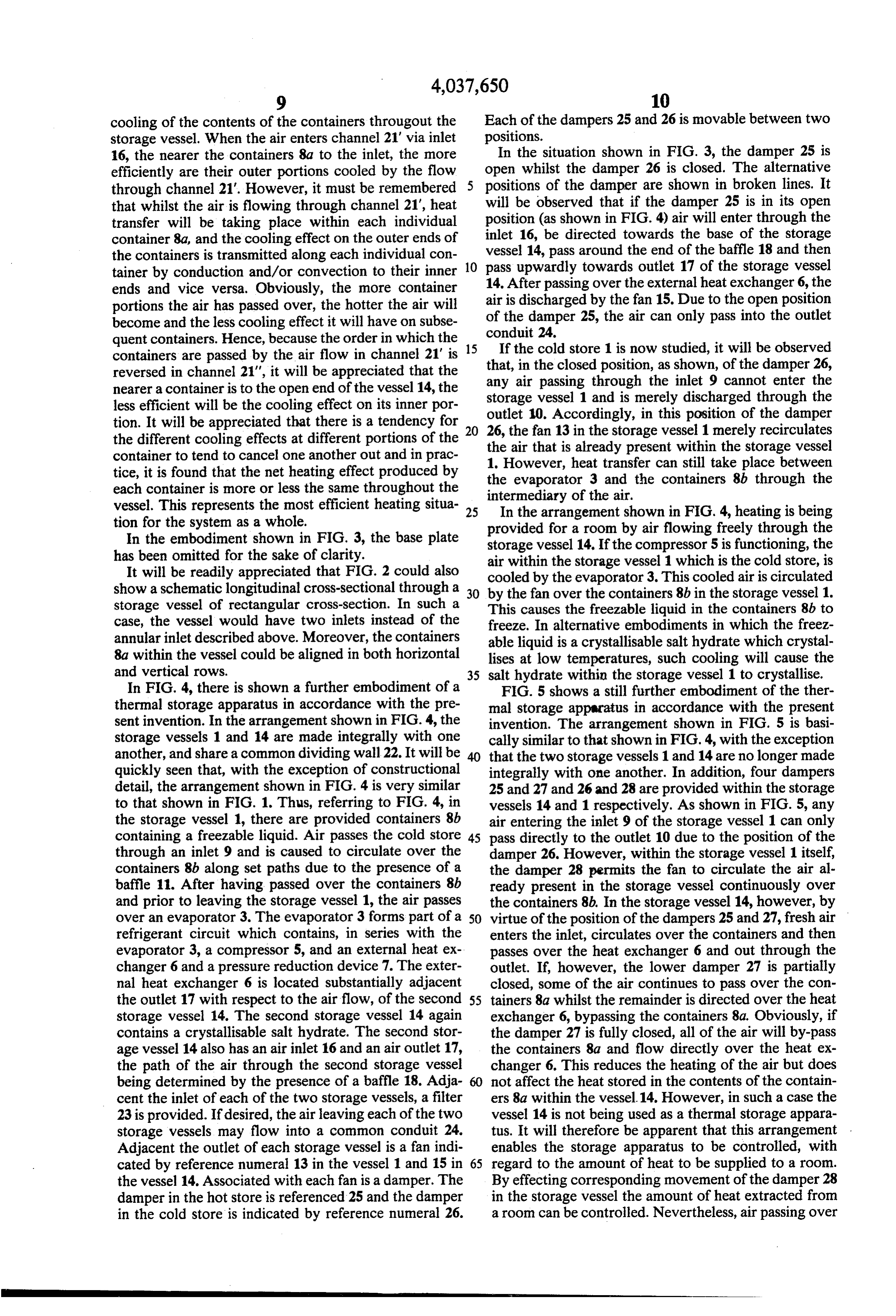
cooling of the contents of the containers througout the Each of the dampers 25 and 26 is movable between two storage vessel. When the air enters channel 21' via inlet positions.
16, the nearer the containers 8a to the inlet, the more In the situation shown in FIG. 3, the damper 25 is efficiently are their outer portions cooled by the flow open whilst the damper 26 is closed. The alternative through channel 21'. However, it must be remembered positions of the damper are shown in broken lines. It that whilst the air is flowing through channel 21", heat will be observed that if the damper 25 is in its open transfer will be taking place within each individual position (as shown in FIG. 4) air will enter through the container 8a, and the cooling effect on the outer ends of inlet 16, be directed towards the base of the storage vessel 14, pass around the end of the baffle 18 and then the containers is transmitted along each individual con 10 pass tainer by conduction and/or convection to their inner 14. After upwardly towards outlet 17 of the storage vessel ends and vice versa. Obviously, the more container air is discharged passing over the external heat exchanger 6, the portions the air has passed over, the hotter the air will of the damper 25,bythe the fan 15. Due to the open position air can only pass into the outlet become and the less cooling effect it will have on subse conduit 24.
quent containers. Hence, because the order in which the 15 If the cold store 1 is now studied, it will be observed containers are passed by the air flow in channel 21" is that, in the closed position, as shown, of the damper 26, reversed in channel 21", it will be appreciated that the nearer a container is to the open end of the vessel 14, the any air passing through the inlet 9 cannot enter the less efficient will be the cooling effect on its inner por outlet 10.vessel storage 1 and is merely discharged through the
Accordingly, in this position of the damper tion. It will be appreciated that there is a tendency for 20 26, the fan 13 in the storage the different cooling effects at different portions of the the air that is already presentvessel 1 merely recirculates within the storage vessel container to tend to cancel one another out and in prac 1. However, heat transfer can still take tice, it is found that the net heating effect produced by the evaporator 3 and the containers 8bplace between through the each container is more or less the same throughout the intermediary of the air.
vessel. This represents the most efficient heating situa 25 In the arrangement shown in FIG. 4, heating is being tion for the system as a whole. provided for a room by air flowing freely through the In the embodiment shown in FIG. 3, the base plate storage vessel 14. If the compressor 5 is functioning, the has been omitted for the sake of clarity. air within the storage vessel 1 which is the cold store, is It will be readily appreciated that FIG. 2 could also cooled by the evaporator 3. This cooled air is circulated show a schematic longitudinal cross-sectional through a 30 by the fan over the containers 8b in the storage vessel 1. storage vessel of rectangular cross-section. In such a This causes the freezable liquid in the containers 8b to case, the vessel would have two inlets instead of the freeze. In alternative embodiments in which the freez annular inlet described above. Moreover, the containers able liquid is a crystallisable salt hydrate which crystal 8a within the vessel could be aligned in both horizontal lises at low temperatures, such cooling will cause the and vertical rows. 35 salt hydrate within the storage vessel 1 to crystallise. In FIG. 4, there is shown a further embodiment of a FIG. 5 shows a still further embodiment of the ther thermal storage apparatus in accordance with the pre mal storage apparatus in accordance with the present sent invention. In the arrangement shown in FIG. 4, the invention. The arrangement shown in FIG. 5 is basi storage vessels 1 and 14 are made integrally with one cally similar to that shown in FIG. 4, with the exception another, and share a common dividing wall 22. It will be that the two storage vessels 1 and 14 are no longer made quickly seen that, with the exception of constructional integrally with one another. In addition, four dampers detail, the arrangement shown in FIG. 4 is very similar 25 and 27 and 26 and 28 are provided within the storage to that shown in FIG. 1. Thus, referring to FIG. 4, in vessels 14 and 1 respectively. As shown in FIG. 5, any the storage vessel 1, there are provided containers 8b air entering the inlet 9 of the storage vessel 1 can only containing a freezable liquid. Air passes the cold store 45 pass directly to the outlet 10 due to the position of the through an inlet 9 and is caused to circulate over the damper 26. However, within the storage vessel 1 itself, containers 8b along set paths due to the presence of a the damper 28 permits the fan to circulate the air al baffle 11. After having passed over the containers 8b ready present in the storage vessel continuously over and prior to leaving the storage vessel 1, the air passes the containers 8b. In the storage vessel 14, however, by over an evaporator 3. The evaporator 3 forms part of a 50 virtue of the position of the dampers 25 and 27, fresh air refrigerant circuit which contains, in series with the enters the inlet, circulates over the containers and then evaporator 3, a compressor 5, and an external heat ex passes over the heat exchanger 6 and out through the changer 6 and a pressure reduction device 7. The exter outlet. If, however, the lower damper 27 is partially nal heat exchanger 6 is located substantially adjacent closed, some of the air continues to pass over the con the outlet 17 with respect to the airflow, of the second 55 tainers 8a whilst the remainder is directed over the heat storage vessel 14. The second storage vessel 14 again exchanger 6, bypassing the containers 8a. Obviously, if contains a crystallisable salt hydrate. The second stor the damper 27 is fully closed, all of the air will by-pass age vessel 14 also has an air inlet 16 and an air outlet 17, the containers 8a and flow directly over the heat ex the path of the air through the second storage vessel changer 6. This reduces the heating of the air but does being determined by the presence of a baffle 18. Adja not affect the heat stored in the contents of the contain cent the inlet of each of the two storage vessels, a filter ers 8a within the vessel. 14. However, in such a case the 23 is provided. If desired, the air leaving each of the two vessel 14 is not being used as a thermal storage appara storage vessels may flow into a common conduit 24. tus. It will therefore be apparent that this arrangement Adjacent the outlet of each storage vessel is a fan indi enables the storage apparatus to be controlled, with cated by reference numeral 13 in the vessel 1 and 15 in 65 regard to the amount of heat to be supplied to a room. the vessel 14. Associated with each fan is a damper. The By effecting corresponding movement of the damper 28 damper in the hot store is referenced 25 and the damper in the storage vessel the amount of heat extracted from in the cold store is indicated by reference numeral 26. a room can be controlled. Nevertheless, air passing over
Page 14
the heat exchanger 6 will extract heat therefrom. The tional heating element may be provided in either store refrigerant passing through the heat exchanger 6 will or in the air outlet or outlets either to heat the interior thus be cooled, and this will affect the contents of the of the storage vessels or to increase the temperature of containers 8b within the storage vessel 1. Moreover, by the air being discharged.
regulating the volume of the air flow through the ap 5 I claim: .
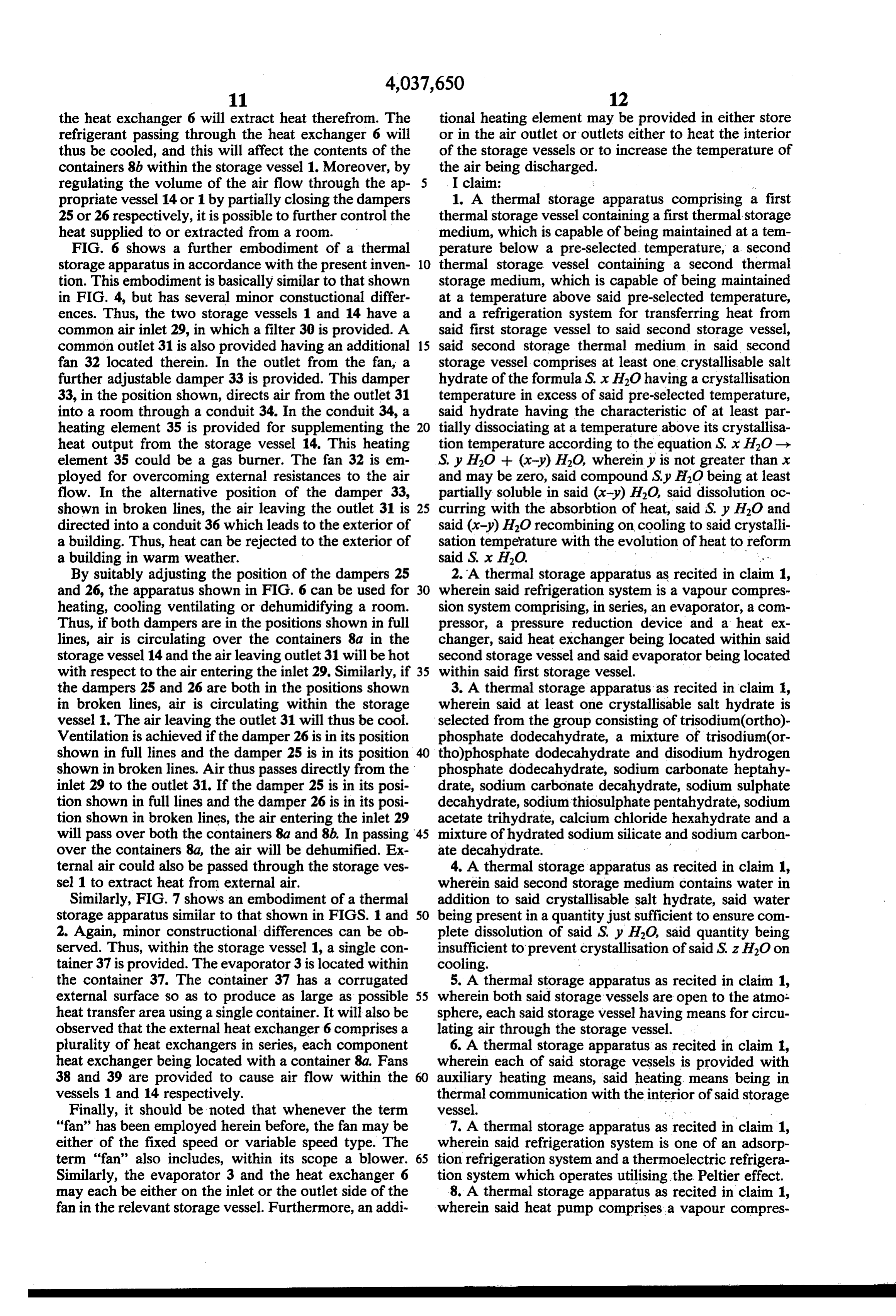
propriate vessel 14 or 1 by partially closing the dampers 1. A thermal storage apparatus comprising a first 25 or 26 respectively, it is possible to further control the thermal storage vessel containing a first thermal storage heat supplied to or extracted from a room. medium, which is capable of being maintained at a tem FIG. 6 shows a further embodiment of a thermal perature below a pre-selected temperature, a second storage apparatus in accordance with the present inven 10 thermal storage vessel containing a second thermal tion. This embodiment is basically similar to that shown storage medium, which is capable of being maintained in FIG. 4, but has several minor constuctional differ at a temperature above said pre-selected temperature, ences. Thus, the two storage vessels 1 and 14 have a and a refrigeration system for transferring heat from common air inlet 29, in which a filter 30 is provided. A said first storage vessel to said second storage vessel, common outlet 31 is also provided having an additional 15 said second storage thermal medium in said second fan 32 located therein. In the outlet from the fan, a storage vessel comprises at least one crystallisable salt further adjustable damper 33 is provided. This damper hydrate of the formula S, x H2O having a crystallisation 33, in the position shown, directs air from the outlet 31 temperature in excess of said pre-selected temperature, into a room through a conduit 34. In the conduit 34, a said hydrate having the characteristic of at least par heating element 35 is provided for supplementing the 20 tially dissociating at a temperature above its crystallisa heat output from the storage vessel 14. This heating tion temperature according to the equation S. x HO-> element 35 could be a gas burner. The fan 32 is em S. y H.O + (x-y) HO, whereiny is not greater than x ployed for overcoming external resistances to the air and may be zero, said compound Sy HO being at least flow. In the alternative position of the damper 33, partially soluble in said (x-y) HO, said dissolution oc shown in broken lines, the air leaving the outlet 31 is 25 curring with the absorbition of heat, said S. Jy HO and directed into a conduit 36 which leads to the exterior of said (x-y) HO recombining on cooling to said crystalli a building. Thus, heat can be rejected to the exterior of sation temperature with the evolution of heat to reform a building in warm weather. said S. x H2O. .. By suitably adjusting the position of the dampers 25 2. A thermal storage apparatus as recited in claim 1, and 26, the apparatus shown in FIG. 6 can be used for 30 wherein said refrigeration system is a vapour compres heating, cooling ventilating or dehumidifying a room. sion system comprising, in series, an evaporator, a com Thus, if both dampers are in the positions shown in full pressor, a pressure reduction device and a heat ex lines, air is circulating over the containers 8a in the changer, said heat exchanger being located within said storage vessel 14 and the air leaving outlet 31 will be hot second storage vessel and said evaporator being located with respect to the air entering the inlet 29. Similarly, if 35 within said first storage vessel. the dampers 25 and 26 are both in the positions shown 3. A thermal storage apparatus as recited in claim 1, in broken lines, air is circulating within the storage wherein said at least one crystallisable salt hydrate is vessel 1. The air leaving the outlet 31 will thus be cool. selected from the group consisting of trisodium(ortho)- Ventilation is achieved if the damper 26 is in its position phosphate dodecahydrate, a mixture of trisodium(or shown in full lines and the damper 25 is in its position tho)phosphate dodecahydrate and disodium hydrogen shown in broken lines. Air thus passes directly from the phosphate dodecahydrate, sodium carbonate heptahy inlet 29 to the outlet 31. If the damper 25 is in its posi drate, sodium carbonate decahydrate, sodium sulphate tion shown in full lines and the damper 26 is in its posi decahydrate, sodiumthiosulphate pentahydrate, sodium tion shown in broken lines, the air entering the inlet 29 acetate trihydrate, calcium chloride hexahydrate and a will pass over both the containers 8a and 8b. In passing 45 mixture of hydrated sodium silicate and sodium carbon over the containers 8a, the air will be dehumified. Ex ate decahydrate. - ternal air could also be passed through the storage ves 4. A thermal storage apparatus as recited in claim 1, sel 1 to extract heat from external air. wherein said second storage medium contains water in Similarly, FIG. 7 shows an embodiment of a thermal addition to said crystallisable salt hydrate, said water storage apparatus similar to that shown in FIGS. 1 and 50 being present in a quantity just sufficient to ensure com 2. Again, minor constructional differences can be ob plete dissolution of said S. y HO, said quantity being served. Thus, within the storage vessel 1, a single con insufficient to prevent crystallisation of said S. z H2O on tainer 37 is provided. The evaporator 3 is located within cooling. .
the container 37. The container 37 has a corrugated 5. A thermal storage apparatus as recited in claim 1, external surface so as to produce as large as possible 55 wherein both said storage vessels are open to the atmos heat transfer area using a single container. It will also be sphere, each said storage vessel having means for circu observed that the external heat exchanger 6 comprises a lating air through the storage vessel. plurality of heat exchangers in series, each component 6. A thermal storage apparatus as recited in claim 1, heat exchanger being located with a container 8a, Fans wherein each of said storage vessels is provided with 38 and 39 are provided to cause air flow within the auxiliary heating means, said heating means being in vessels 1 and 14 respectively. thermal communication with the interior of said storage Finally, it should be noted that whenever the term vessel. .. . . "fan' has been employed herein before, the fan may be 7. A thermal storage apparatus as recited in claim 1, either of the fixed speed or variable speed type. The wherein said refrigeration system is one of an adsorp term "fan' also includes, within its scope a blower. 65 tion refrigeration system and a thermoelectric refrigera Similarly, the evaporator 3 and the heat exchanger 6 tion system which operates utilising the Peltier effect. may each be either on the inlet or the outlet side of the 8. A thermal storage apparatus as recited in claim 1, fan in the relevant storage vessel. Furthermore, an addi wherein said heat pump comprises a vapour compres
Page 15
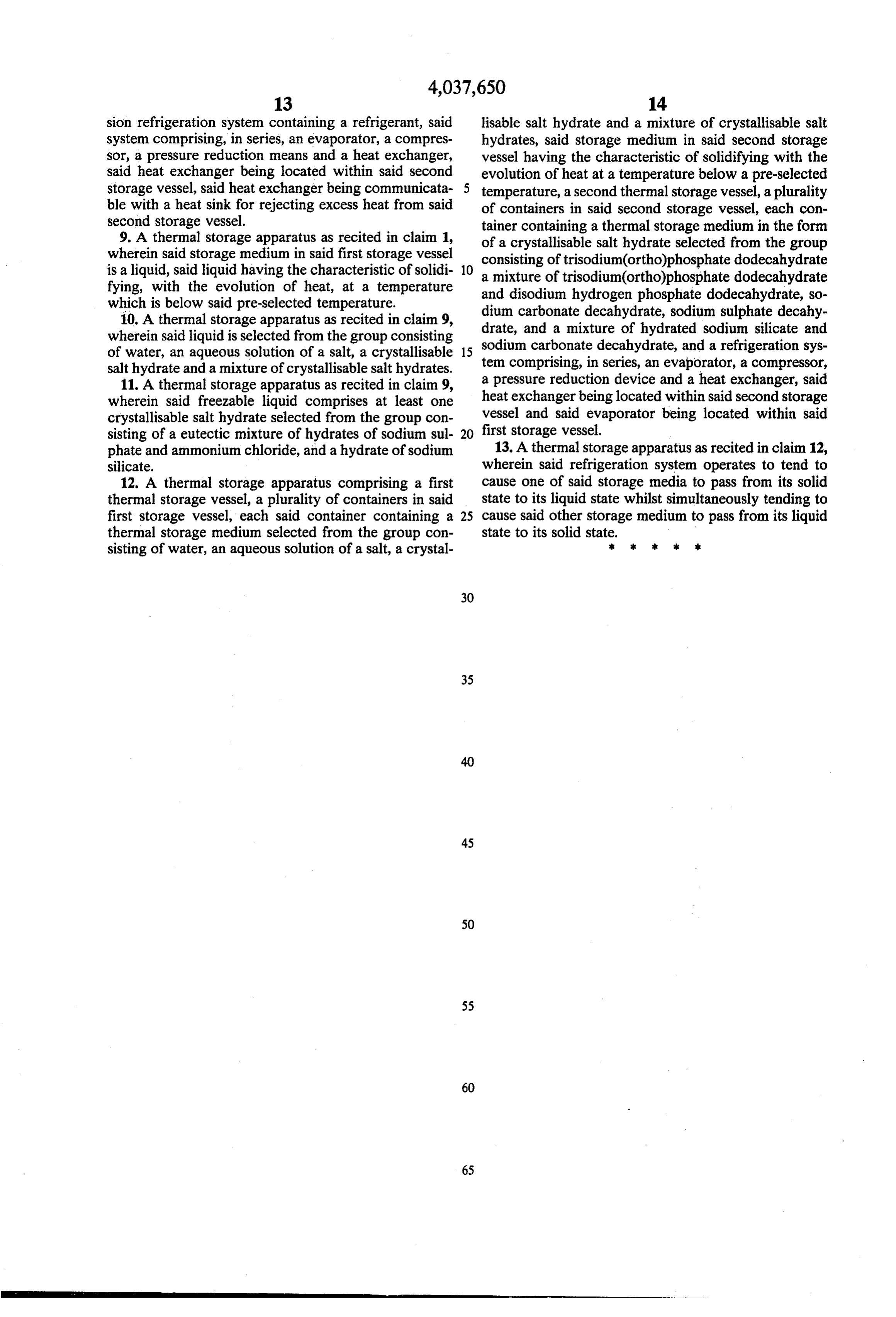
sion refrigeration system containing a refrigerant, said lisable salt hydrate and a mixture of crystallisable salt system comprising, in series, an evaporator, a compres hydrates, said storage medium in said second storage sor, a pressure reduction means and a heat exchanger, vessel having the characteristic of solidifying with the said heat exchanger being located within said second evolution of heat at a temperature below a pre-selected storage vessel, said heat exchanger being communicata temperature, a second thermal storage vessel, a plurality ble with a heat sink for rejecting excess heat from said of containers in said second storage vessel, each con second storage vessel. tainer containing a thermal storage medium in the form 9. A thermal storage apparatus as recited in claim 1, of a crystallisable salt hydrate selected from the group wherein said storage medium in said first storage vessel consisting of trisodium(ortho)phosphate dodecahydrate is a liquid, said liquid having the characteristic of solidi 10 a mixture of trisodium(ortho)phosphate dodecahydrate fying, with the evolution of heat, at a temperature and disodium hydrogen phosphate dodecahydrate, so which is below said pre-selected temperature. dium carbonate decahydrate, sodium sulphate decahy 10. A thermal storage apparatus as recited in claim 9, drate, and a mixture of hydrated sodium silicate and wherein said liquid is selected from the group consisting sodium carbonate decahydrate, and a refrigeration sys of water, an aqueous solution of a salt, a crystallisable 15 tem comprising, in series, an evaporator, a compressor, salt hydrate and a mixture of crystallisable salt hydrates.
11. A thermal storage apparatus as recited in claim 9, a pressure reduction device and a heat exchanger, said wherein said freezable liquid comprises at least one heat exchanger being located within said second storage crystallisable salt hydrate selected from the group con vessel and said evaporator being located within said sisting of a eutectic mixture of hydrates of sodium sul 20 first storage vessel.
phate and ammonium chloride, and a hydrate of sodium 13. Athermal storage apparatus as recited in claim 12, silicate. wherein said refrigeration system operates to tend to 12. A thermal storage apparatus comprising a first cause one of said storage media to pass from its solid thermal storage vessel, a plurality of containers in said state to its liquid state whilst simultaneously tending to first storage vessel, each said container containing a 25 cause said other storage medium to pass from its liquid thermal storage medium selected from the group con state to its solid state.
sisting of water, an aqueous solution of a salt, a crystal sk s
Provenance
- Collection
- Cited prior art
- Original PDF
- patentimages.storage.googleapis.com →
- Filed
- 1975-05-23
- Pages
- 15
- Method
- pdftotext (the PDF's own text layer) + pdftoppm 300dpi page scans
- Source
- Google Patents bibliographic record
- Granted
- 1977-07-26
- Inventors
- John Edward Randall; National Research Development Corp UK
- Transcribed from
- patentimages.storage.googleapis.com →