patent · US4275363
Method of and apparatus for driving an ultrasonic transducer including a phase locked loop and a sweep circuit
23 June 1981
Page 1 — bibliographic record
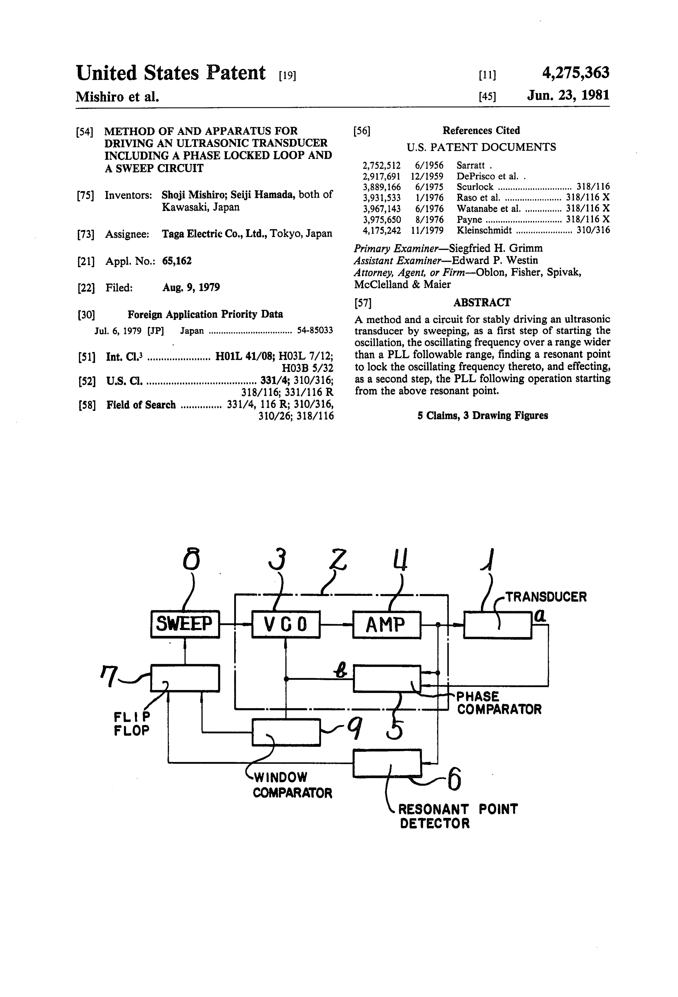
United States Patent (19) 11) 4,275,363 Mishiro et al. 45) Jun. 23, 1981 54 METHOD OF AND APPARATUS FOR 56) References Cited DRIVING ANULTRASONIC TRANSDUCER U.S. PATENT DOCUMENTS
INCLUDING A PHASE LOCKED LOOP AND
A SWEEP CIRCUIT 2,752,512 6/1956 Sarratt.
3,889, 166 6/1975 Scurlock .............................. 318/116 75) Inventors: Shoji Mishiro; Seiji Hamada, both of 3,931,533 1/1976 Raso et al. .......... ... 318/116 X Kawasaki, Japan 3,967,143 6/1976 Watanabe et al. .. ... 318/116 X 3,975,650 8/1976 Payne ............................... 38/116 X 73) Assignee: Taga Electric Co., Ltd., Tokyo, Japan 4,175,242 11/1979 Kleinschmidt ....................... 310/316 Primary Examiner-Siegfried H. Grimm (21) Appl. No.: 65,162 Assistant Examiner-Edward P. Westin Attorney, Agent, or Firm-Oblon, Fisher, Spivak, (22 Filed; Aug. 9, 1979 McClelland & Maier
(30) Foreign Application Priority Data A method and a circuit for stably driving an ultrasonic Jul. 6, 1979 (JP) Japan .................................. 54-85033 transducer by sweeping, as a first step of starting the oscillation, the oscillating frequency over a range wider 51) Int. Cl. ....................... H01L 41/08; HO3L 7/12; than a PLL followable range, finding a resonant point HO3B 5/32 to lock the oscillating frequency thereto, and effecting, 52 U.S.C. ...................................... 331/4; 310/316; as a second step, the PLL following operation starting 318/116; 331/116 R from the above resonant point.
310/26; 318/116 5 Claims, 3 Drawing Figures
TRANSDUCER
COMPARATOR
COMPARATOR
RESONANT POINT
DETECTOR
Page 2
Drawing sheet — no readable text.
Page 3
Drawing sheet — no readable text.
Page 4
of the phase locked loop without causing erroneous
METHOD OF AND APPARATUS FOR DRIVING operation.
ANULTRASONIC TRANSDUCER INCLUDING A The second object of the present invention is to pro PHASE LOCKED LOOP AND A SWEEP CIRCUIT vide a method which is capable of preventing erroneous 5 operation such as locking at subresonant points.
DESCRIPTION OF THE INVENTION The third object of the present invention is to provide The present invention relates to an ultrasonic wave point a method which automatically finds a new resonant generating apparatus with a sweep locked PLL, and when the to lock the oscillating frequency thereto even particularly to a method of driving an ultrasonic trans O exceed theresonant frequency is so greatly changed as to followable range set by the phase locked ducer and a circuit therefor.
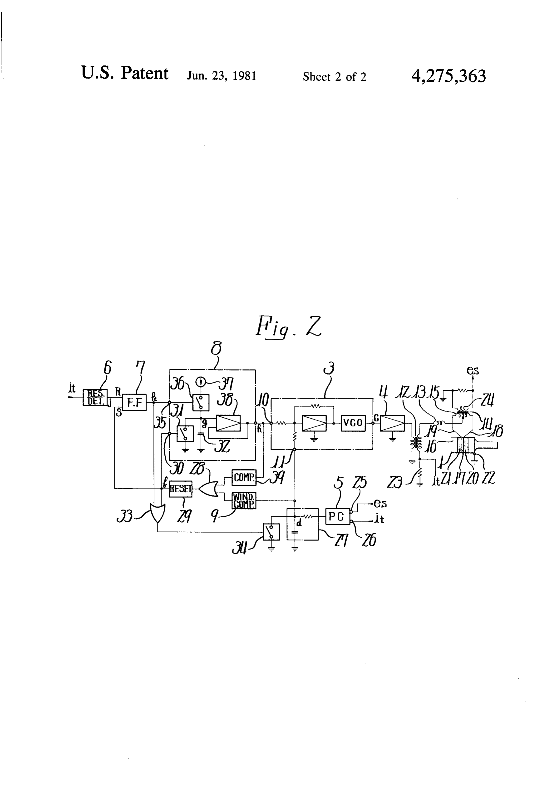
In general, ultrasonic transducers employed for ultra loop. FIG. 1 is a block diagram showing the principle ac sonic appliances should be operated at their resonant cording to the present invention. frequencies so that their electro-mechanical conversion FIG. 2 is a circuit diagram showing a preferred em efficiencies can be enhanced. The mechanical charac 15 teristics of resonance, however, exhibit sharp Q values, bodiment according to the present invention,
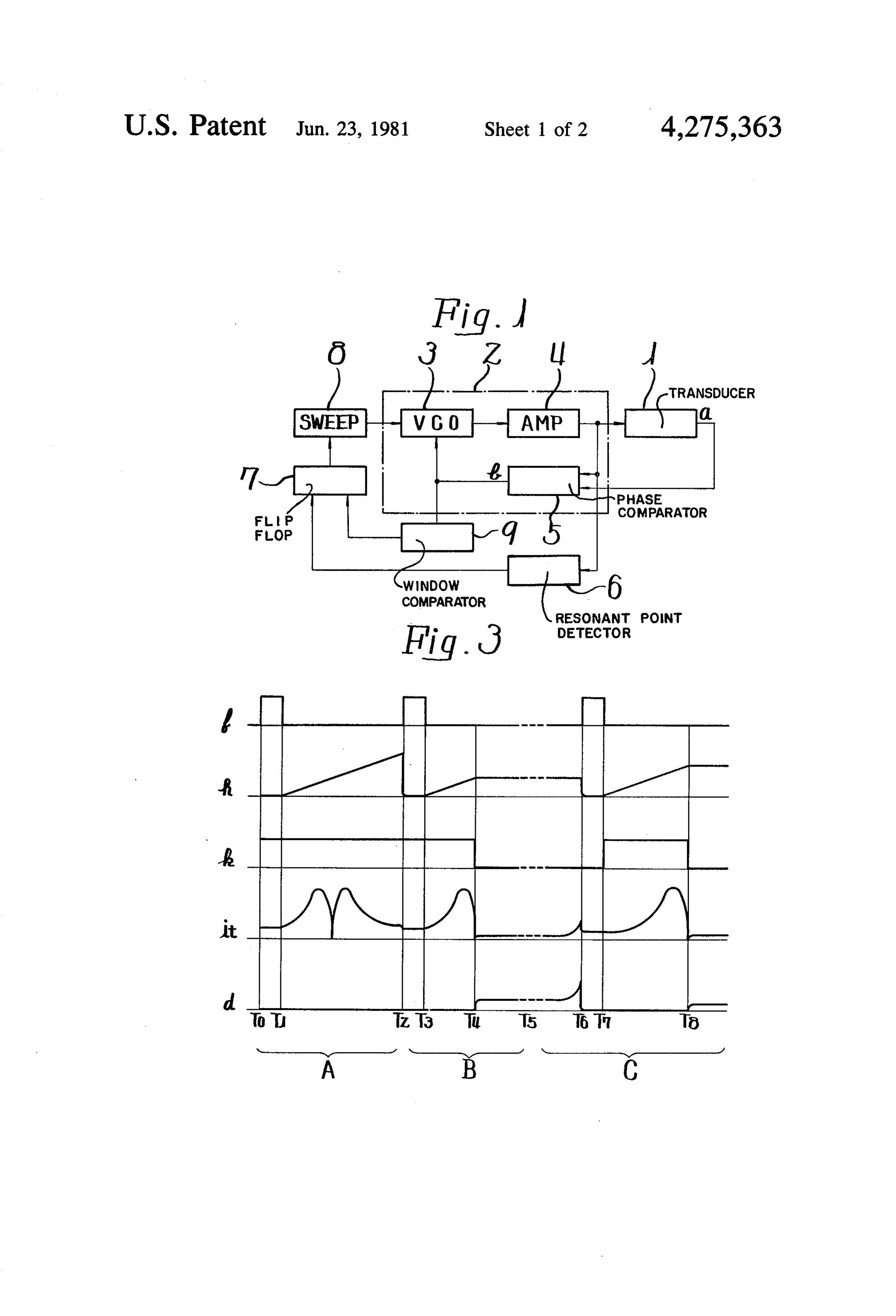
Particularly, the Qvalues appear when the amplitude of of the portions. is a timing chart showing waveforms at each vibration is amplified using a horn. Moreover, the reso nant frequencies vary in accordance with external con theThe invention is described below in conjunction with accompanying drawings. Referring first to FIG. 1, ditions such as the temperature at which the ultrasonic an ultrasonic transducer 1 is connected to a PLL fol transducer is used, driving level or loading level. There lower, i.e., to a phase locked loop 2. The phase locked fore, a motional feedback oscillator has been extensively loop 2 consists of a voltage controlled oscillator 3, an employed, in which the oscillating frequency of a driv ing circuit changes while following the changes in reso amplifier nected in 4 and a phase comparator 5, which are con the form of a loop. To the amplifier 4 has been nant frequency of the ultrasonic transducer. 25 connected the ultrasonic transducer 1 which feeds vi
Furthermore, there has recently been employed a bratory velocity signals a to the phase comparator 5. To PLL follower circuit having a voltage controlled oscil the amplifier 4 is connected a resonant point detector 6 lator which is controlled by the output of a phase com which is connected to a reset terminal R of a flip-flop 7. parator which detects a shifted value from a predeter A sweep circuit 8 is connected between the output side mined phase difference between a driving voltage or a 30 the flip-flop 7 and the voltage controlled oscillator 3. driving current of the ultrasonic transducer and a vibra of Further, a window comparator 9 is connected between tory velocity signal, and in which the ultrasonic trans the ducer is driven by the oscillating frequency of the volt flopphase7.
comparator 5 and a set terminal S of the flip age controlled oscillator so that the oscillating fre 35 When the oscillation is started, the output voltage of quency is varied while following the resonant fre the sweep circuit 8 is first reset to zero and, then, the quency of the ultrasonic transducer. sweeping is started. During the period of sweeping, the However, a serious problem is presented when such a output voltage b of the phase comparator 5 is held at a PLL follower circuit is used, i.e., when the phase center value in the PLL followable range. The output locked loop is employed. In many ultrasonic appliances of the sweep circuit 8 is fed as another control input to such as plastic welders and machine tools, the resonant the voltage controlled oscillator 3 so that its oscillating frequency varies depending upon the horns and tools of frequency is swept over a frequency range wider than various types and the degree of wear of the tools. If the the PLL followable range. Hence, the ultrasonic trans change is too great, the followable range of the phase ducer 1 is driven by a driving voltage or a driving cur locked loop is exceeded causing the apparatus to be rent which is swept from a low frequency toward a high inoperative. Therefore, the horns and tools must be 45 frequency. Then, the resonant point of the ultrasonic manufactured with high precision in regard to the reso transducer 1 is detected by the resonant point detector nant frequencies, and in addition, strict limits must be 6 which produces an output to reset the flip-flop 7, imposed on the degree of wear of the horns and tools. If whereby the sweeping function of the sweep circuit 8 is an attempt is made to broadly set the following range, 50 halted. Therefore, the oscillating frequency of the volt there develops such serious trouble that abnormal oper age controlled oscillator 3 is locked to a resonant point ation takes place due to the range of operating fre of the ultrasonic transducer 1.
quency of a vibratory velocity detector of the ultrasonic Then, the output voltage b of the phase comparator 5 transducer being narrow. This is because, if the driving is allowed to change from the center value of the PLL frequency greatly deviates from the resonant frequency 55 followable range, the frequency control of the voltage of the ultrasonic transducer, the intensity of the vibra controlled oscillator 3 is handled by the phase compara tory velocity signals is markedly reduced to fall outside tor 5 and the PLL operation begins. Accordingly, even the detectable range of the phase comparator, whereby when the resonant frequency of the ultrasonic trans the phase comparator operates improperly. Hence, ac ducer 1 varies due to some causes, the ultrasonic trans cording to the conventional apparatus employing the ducer 1 operates properly if the varied resonant fre phase locked loop, the followable range has been set quency lies within the followable range set by the phase within a range that satisfies the abovementioned func locked loop 2.
tion, and the replaceable horns and tools have been with In this case, the window comparator 9 is always de high precision manufactured to satisfy these require tecting the resonant frequency. Here, if the quantity of ents. 65 change exceeds the followable range of the phase The first object of the present invention is to provide locked loop 2, the window comparator 9 produces an a method which is capable of reliably following the output to set the flip-flop 7, whereby the sweep circuit resonant frequency of an ultrasonic transducer by way 8 is started again to lock the oscillating frequency to a
Page 5
new resonant frequency; the function is then shifted to voltage generator circuit, i.e., the reset pulse f is fed to the PLL operation as mentioned above. a reset terminal 30 of the sweep circuit 8, whereby an The undesirable subresonant frequencies of the ultra analog switch 31 is turned on, the electric charge stored sonic transducer 1 are usually located at points higher in an integrating capacitor 32 is discharged to zero, and than the fundamental resonant frequency. It is therefore the phase compared signal d is reset to zero by the desirable to start the oscillation of the sweep circuit 8 analog switch 34 through an OR circuit 33. from the lower frequency as mentioned above, so that Then, flip-flop 7 is triggered and set by a falling edge the oscillating frequency is not locked to such undesired of the reset pulse f, the analog switch 31 is rendered off frequencies. Further, the ultrasonic transducer 1 may be by the extinction of the reset pulse f, part of the output made up of either an electro-strictive transducer or a 10 voltage k of the flip-flop 7 is fed to a set terminal 35 of magneto-strictive transducer, and its operation mode the sweep circuit 8, and an analog switch 36 is turned on may be based upon either a parallel resonant point or a so that the electric charge is stored in the integrating series resonant point. When the ultrasonic transducer is capacitor 32 which is connected to a constant current operated based upon the series resonant point, however, circuit 37. At the same time, another part of the output it is recommended that an impedance inverter for con 15 voltage of the flip-flop 7 flows through the OR circuit verting a constant voltage supply to a constant current 33 to maintain the analog switch 34 in an on state, so supply be inserted between the output of the amplifier 4 that the phase compared signal d is cramped to zero. and the ultrasonic transducer 1. A charging voltage g of the integrating capacitor 32 A circuit setup embodying the abovementioned prin is received through a high impedance of the amplifier 38 ciple and its operation in conjunction with FIG. 2 are 20 and is converted into a sweep control signal h for the discussed below. The portions referred to FIG. 1 are voltage controlled oscillator 3 in the form of a low denoted by the same reference numerals in FIG. 2. impedance output having equal voltage. Part of the First, the voltage controlled oscillator 3 has two input sweep control signal his fed into the comparator 39. If terminals, i.e., a ramp voltage input terminal 10 and a the sweep control signal h reaches a predetermined phase comparator voltage input terminal 11. The for 25 value, the comparator 39 works to trigger the reset mer terminal receives signals for sweeping oscillation, circuit 29 via the OR circuit 28, so that the sweeping and the latter terminal receives signals for the PLL operation is repeated again starting from the reference operation. These signals control the oscillating fre voltage. This operation determines a maximum value of quency independent of each other. The output c of the the sweep control signal h, i.e., determines a maximum voltage controlled oscillator 3 is amplified by the ampli 30 varying difference in the sweeping frequencies. fier 4, and is applied to a primary coil of the output As a result of the above sweeping, the electro-stric transformer 12. An output voltage produced on a sec tive transducer 16 is swept starting from a low fre ondary coil of the output transformer 12 flows through quency. The transducer current, however, becomes a series matching inductance 13, differentially flows minimal at a parallel resonant frequency. Therefore, if a through a primary coil 15 of a differential transformer 35 minimum value of a detected current signal it through 14 for detecting the vibratory velocity, and flows into transducer is detected by the resonant point detector 6, electro-strictive elements 20, 21 from positive terminals the flip-flop 7 is reset by the output j, whereby the 18, 19 which are insulated by an insulator 17 of an elec charging of the integrating capacitor 32 is terminated by tro-strictive transducer 16 that serves as the ultrasonic the turn off of the analog switch 36. The integrating transducer 1. The electric current further flows from a capacitor 32 maintains the charging voltage g of that negative terminal 22 into a resistor 23 for detecting the state. Accordingly, the oscillating frequency of the current of the transducer, and returns to the secondary voltage controlled oscillator 3 being swept is locked to coil of the output transformer 12. a frequency corresponding to a value of the control The output voltage produced in the secondary coil 24 terminal 10, whereby the analog signal switch 34 is of the differential transformer 14, i.e., a vibratory veloc 45 rendered off, and the phase comparator 5 produces the ity signalls is fed as an input signal to an input terminal phase compared signal d which serves as the PLL con 25 of the phase comparator 5, and a detected signali for trol signal for the voltage controlled oscillator 3 current through transducer produced by the detector thereby to follow the resonant frequency of the electro resistor 23 is fed as an input signal to an input terminal strictive transducer 16.
26 of the phase comparator 5, whereby the phases of 50 During the PLL following operation, the resonant these inputs are compared. A phase compared signal d frequency of the electro-strictive transducer 16 may integrated by a low-pass filter 27 is fed as a PLL control often vary greatly due to a worn-out tool or due to any signal to an input terminal 11 of the voltage controlled other causes making it difficult to perform the PLL oscillator 3. following operation. In such a case, however, the out The varying voltage difference of the phase com 55 put of the phase comparator 5 is greatly changed, caus pared signal d, on the other hand, is monitored by the ing the window comparator 9 to be operated, the reset window comparator 9. If the varying difference ex circuit 29 to be reset, and the sweeping function to be ceeds a predetermined value, the output signal passes continued until the oscillating frequency is locked to a through an OR circuit 28 to trigger a reset circuit 29 so new resonant frequency. Hence, the PLL following that a reset pulse f is produced in the line. Here, the operation is initiated again starting from a new resonant setpoint value of the window comparator 9 determines point.
the frequency range that is to be locked during the PLL The operation of each of the circuits with respect to operation. Further, the above reset circuit 29 has a time is shown in the timing chart of FIG. 3. First, refer power-on-reset function to reliably produce a reset ring to FIG. 3, the abscissa is divided into three sections pulse f when the power supply is turned on. 65 A, B and C. Section A shows the state in which the When the reset circuit 29 is triggered by the turn on phase locked loop 2 is not locked, or shows the state of of the power supply or by the trigger signal from the the sweep circuit 8 and the timing related thereto. Sec window comparator 9, the reset pulse f is fed to a ramp tion B shows the state in which the phase locked loop 2
Page 6
is not locked during the sweeping operation, and section sweeping the frequency of an oscillating signal over a C shows the state in which the resonant point is varied first frequency range;
during the following operation. driving an ultrasonic transducer by applying said With reference to the section A, if the power supply oscillating signal to said ultrasonic transducer; is turned on at a point To, the reset circuit 29 having a detecting the resonant point of said ultrasonic trans power-on-reset function produces the reset pulse f hav ducer during said sweeping; ing a pulse width up to a point T. Hence, the analog stopping the sweeping upon detection of a resonant switch 31 is turned on to discharge the integrating ca point; and pacitor 32, and the flip-flop 7 is set to turn on the analog driving said ultrasonic transducer using a phase switch 36. The analog switch 28 is also turned on. 10 locked loop, where the loop includes a phase com Thereafter, the analog switch 31 is turned off at the parator for comparing the oscillating signal with an falling edge of the reset pulse fat the point T1, and the output signal from the transducer and an oscillator electric charge is stored again in the integrating capaci responsive to the phase comparator for producing tor 32 so that the voltage of the sweep control signal h 15 said oscillating signal.
is gradually increased. As the sweep control signal h cording2. A method of driving an ultrasonic transducer ac rises, the frequency of output c from the voltage con a low frequencyto claim 1, wherein the frequency is swept from trolled oscillator 3 is changed causing the detected cur to a higher frequency. 3. A circuit for driving an ultrasonic transducer com rent signal is through the transducer to be varied. Thus, prising:
as the sweep control signal h rises to point T2, the com ultrasonic transducer means for producing ultrasonic parator 39 produces an output to reset again the reset waves and a phase signal;
circuit 29. This causes the analog switch 31 to be turned amplifier means for driving the ultrasonic means; on and the integrating capacitor 32 to be discharged. phase comparator means for comparing the output of In reference to section B, the operations at each of the said amplifier means with said phase signal and portions at a point T3 are the same as those which took 25 producing a phase difference signal; place at the point T. Here, however, as the sweep voltage controlled oscillator means receiving the control signal h rises up to a point T4, the detected phase difference signal and producing an output for current signal it through the transducer establishes a driving the amplifier means and ultrasonic trans state which develops a resonant point, whereby the ducer means;
resonant point detector 6 produces an output j to reset 30 a phase locked loop including said voltage controlled the flip-flop 7. This causes the analog switch 36 to be oscillator means, said amplifier means and said turned off, and the integrating capacitor 32 maintains phase comparator means capable of following a the potential of that state. At the same time, the analog first frequency range;
switch 34 is turned off, and the phase compared signald sweep circuit means for sweeping an oscillating fre acquires a value corresponding to the phsae difference 35 quency and driving said voltage controlled oscilla between the vibratory velocity signalls and the detected tor means, being connected to said voltage con current signal it through the transducer to perform the trolled oscillator means and being capable of stop PLL following operation. Symbol Ts denotes that the ping the operation of said phase locked loop and following operation is being carried out. sweeping said oscillating frequency over a second In reference to section C, when the resonant point has frequency range wider than said first frequency exceeded the followable range of the phase locked loop range; and 2 due to a worn-out tool or for any other reasons during a resonant point detector being connected to the the PLL following operation as mentioned earlier, the output of said amplifier means and being capable of phase compared signal d is produced as designated at a detecting the current through said ultrasonic trans point Ts. The phase compared signal d is detected by 45 ducer and locking said sweep circuit means at a the window comparator 9 at the point T6 to reset again resonant point of said ultrasonic transducer means the reset circuit 29. Hence, the reset pulse fis produced so as to render said phase locked loop operative. having a width of from T6 to T7. At the point T, the 4. A circuit for driving an ultrasonic transducer com same operation as that which took place at T1 or T3 is prising:
performed, and the oscillating frequency is locked to a 50 ultrasonic transducer means for producing ultrasonic new resonant point at a point T8. Consequently, the waves and a phase signal;
PLL following operation is performed with a new reso amplifier means for driving the ultrasonic means; nant frequency. phase comparator means for comparing the output of The aforementioned embodiment has dealt with the said amplifier means with said phase signal and case in which the resonant point detector 6 detected a 55 producing a phase difference signal; point at which the transducer current driven at a paral voltage controlled oscillator means receiving the lel resonant frequency was minimum. The apparatus, phase difference signal and producing an output for however, may be so constructed that the resonant point driving the amplifier means and ultrasonic trans detector 6 detects a point at which the transducer cur ducer means;
rent becomes maximum. Namely, since the PLL opera a phase locked loop including said voltage controlled tion follows the resonant point after the oscillating fre oscillator means, said amplifier means and said quency has been swept and locked by the resonant point phase comparator means capable of following a detector 6, the resonant point detector 6 needs not be first frequency range;
designed to have a high precision but may be simply sweep circuit means for sweeping an oscillating fre constructed. quency and driving said voltage controlled oscilla We claim: tor means, being connected to said voltage con 1. A method of driving an ultrasonic transducer com trolled oscillator means and being capable of stop prising the steps of: ping the operation of said phase locked loop and
Page 7
sweeping said oscillating frequency over a second driving the amplifier means and ultrasonic trans frequency range wider than said first frequency ducer means;
range; a phase locked loop including said voltage controlled a resonant point detector being connected to the oscillator means, said amplifier means and said output of said amplifier means and being capable of 5 phase comparator means capable of following a detecting the current through said ultrasonic trans first frequency range;
ducer and locking said sweep circuit means at a sweep circuit means for sweeping an oscillating fre resonant point of said ultrasonic transducer means quency and driving said voltage controlled oscilla so as to render said phase locked loop operative; to tor means, being connected to said voltage con and trolled oscillator means and being capable of stop ping the operation of said phase locked loop and a window comparator connected between said phase sweeping said oscillating frequency over a second comparator means and said sweep circuit means, frequency range wider than said first frequency said window comparator being capable of detect range;
ing the phase difference signal in said phase locked 15 a resonant point detector being connected to the loop to drive the sweep circuit means when the output of said amplifier means and being capable of phase difference signal exceeds the range set by the detecting the current through said ultrasonic trans phase locked loop and thereby lock the oscillating ducer and locking said sweep circuit means at a frequency to a new resonant point. resonant point of said ultrasonic transducer means 5. A circuit for driving an ultrasonic transducer com 20 so as to render said phase locked loop operative; prising: and ultrasonic transducer means for producing ultrasonic a comparator connected between an input terminal waves and a phase signal; and output terminal of said sweep circuit means, amplifier means for driving the ultrasonic means; 25 said comparator detecting the condition of the phase comparator means for comparing the output of . sweep circuit means to reset said sweep circuit said amplifier means with said phase signal and means when the said oscillating frequency of said sweep circuit means has reached a predetermined producing a phase difference signal; value, so that sweeping is effected again from a voltage controlled oscillator means receiving the reference frequency. ". phase difference signal and producing an output for 30 :
Provenance
- Collection
- Cited prior art
- Original PDF
- patentimages.storage.googleapis.com →
- Filed
- 1979-08-09
- Pages
- 7
- Method
- pdftotext (the PDF's own text layer) + pdftoppm 300dpi page scans
- Source
- Google Patents bibliographic record
- Granted
- 1981-06-23
- Inventors
- Shoji Mishiro; Seiji Hamada; Taga Electric Co Ltd
- Transcribed from
- patentimages.storage.googleapis.com →