patent · US2672288
Sensing of perforated statistical records
16 March 1954
Page 1
Drawing sheet — no readable text.
Page 2
Drawing sheet — no readable text.
Page 3
Drawing sheet — no readable text.
Page 4
Patented Mar. 16, 1954
UNITED STATES PATENT OFFICE
- SENSING OF PERFORATED STATSTICAL
RECORDS
John Perrin, Croydon, England, assignor to
Powers-Samas Accounting Machine Limited,
London, England, a British company
Application May 9, 1951, Serial No. 225,310
Claims priority, application Great Britain
This invention relates to a machine for sort 2 ing perforated record cards in which data is re poly methyl methacrylate, preferably of thekind corded by perforations disposed in rows consid known as “Perspex,' and has a highly polished ered along one dimension of a card and in col outer surface from which sharp edges are re lumns considered along the other dimension of moved to avoid any substantial loss of light paSS the card, the data, indicating positions of each ing along the element.
row having like significance, said machine icon In order that the invention may be clearly prising a plurality of card receiving compart understood an embodiment thereof Will.now be ments corresponding in number to the number described by way of example with reference to the accompanying diagrammatic drawings in of data-indicating positions in a single column 10 which:
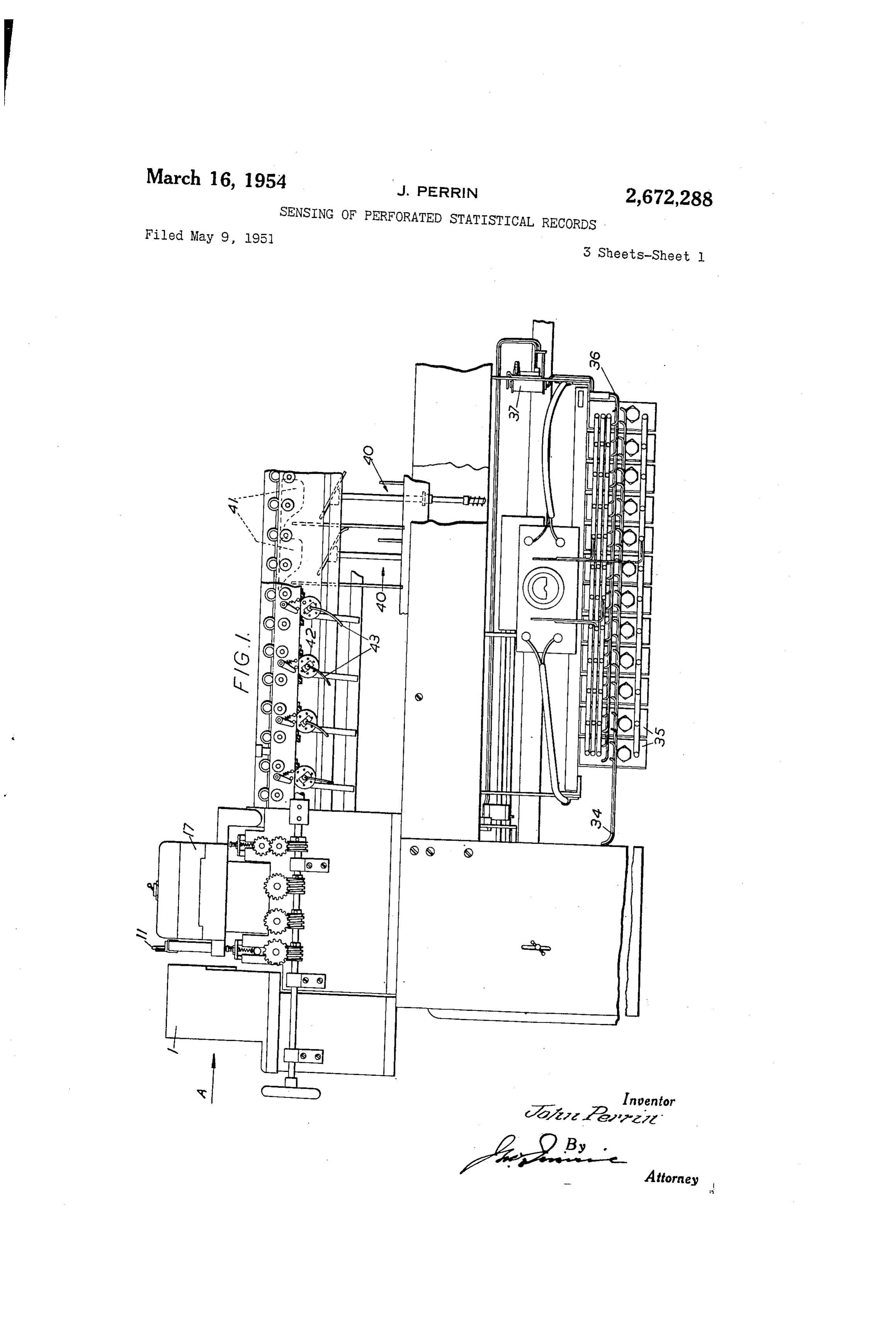
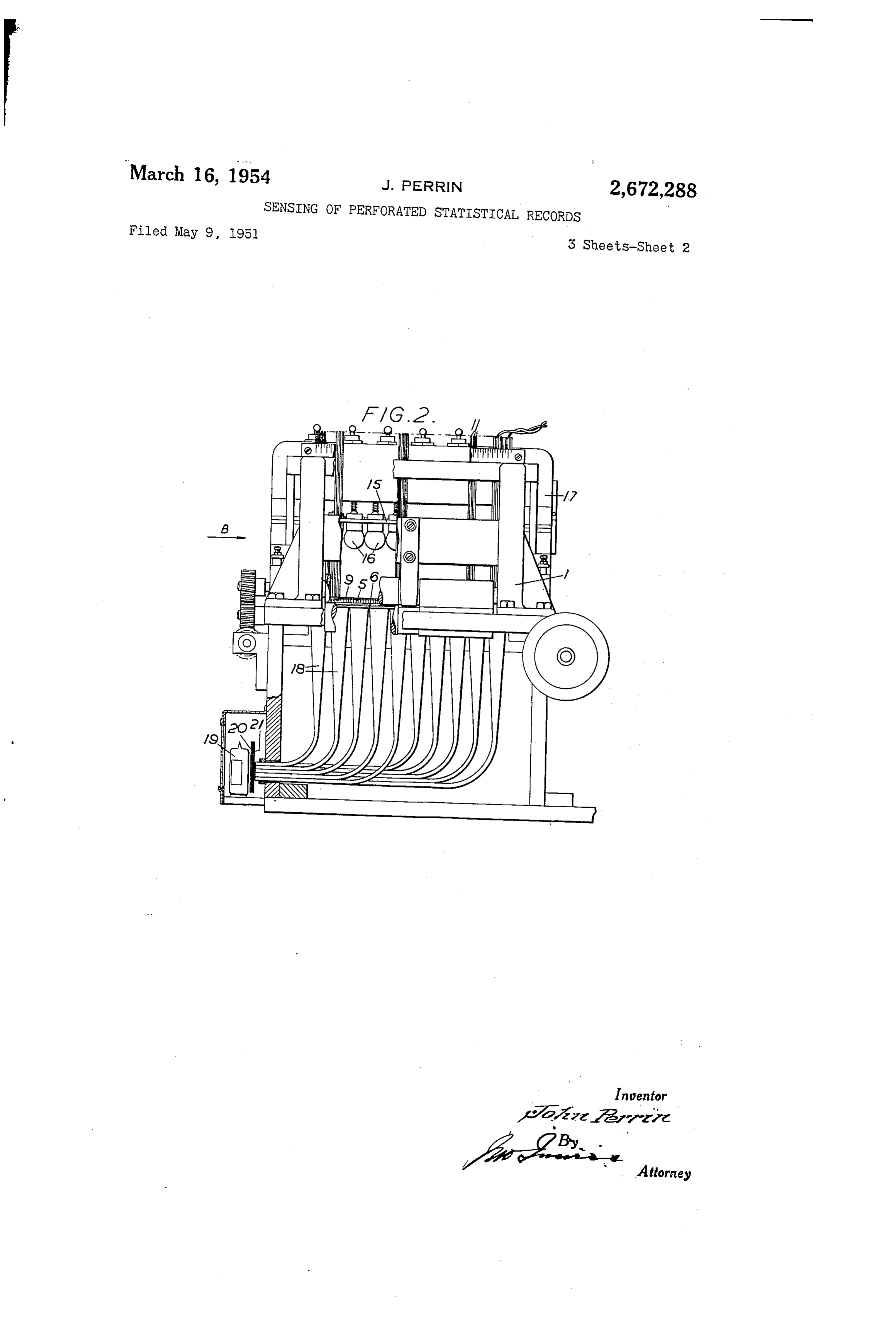
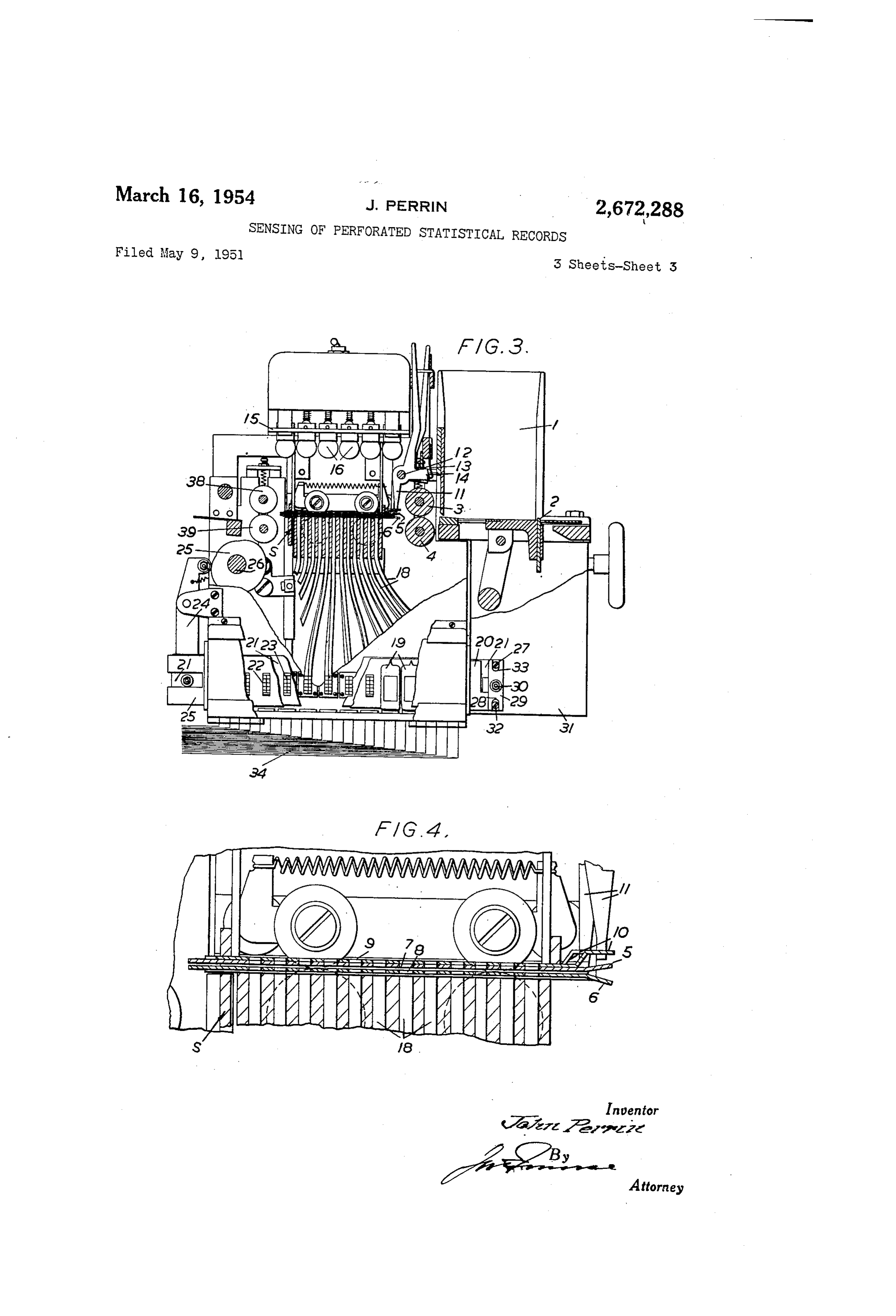
“Of a card, a card guide for each said compart ment set normally to prevent a card from entering Fig. 1 is a side elevation of a part of a ma the compartment and movable to deflect a card chine cards. for sorting perforated statistical record into the compartment, and a timing device for *each compartment operable as the result of an Fig. 2 is an end view of the sensing head of the 'impulse received thereby, following a sensing op 15 and machine looking in direction of arrow A, Fig. 1, being partly broken away, ceration performed on a card to effect movement of the card guide for the compartment to deflect Fig. 3 is a side elevation, partly in Section, the sensed card into the compartment. A ma looking in direction of arrow B, Fig. 2, and chine of this kind is referred to in the claims 20 Scale. Fig. 4 shows a detail of Fig. 3 to an enlarged
Scribed. hereto as a machine of the class de
Referring to the drawings, perforated record
It is a main object of the present invention to cards to be sorted are placed as a pile into a provide a new form of apparatus for sensing magazine from the bottom of which they are statistical record cards and effecting operation 25 fed one at a time by a reciprocating picker. 2 of of said timing devices as a result of sensing op known construction driven from the main drive cerations performed on the cards. of the machine by mechanism not shown. The ‘As is well understood in the art, record cards picker delivers a card to feed rollers 3, 4 which are usually so made that the data-indicating move the card into a sensing chamber formed positions are arranged with respect to the card by a top perforated plate 5, Figs... 3 and $4, and in horizontal rows and vertical colurans and the 3) a bottom perforated plate 6 and also into en record card usually comprises twelve horizontal gagement with a movable stop S operated, in Well rows whereas the number of vertical columns known manner, by mechanism not shown, which may vary according to the capacity of the card. locates the card in the sensing chamber. For example, a card may contain twenty-one, 35 The top and botton plates forming the Sens thirty-six, forty-five, or sixty-five vertical col ing chamber comprise aligned apertures 7, 8, one S. for each data-indicating position on the card, In carrying the investion into effect, a card and resting on the upper surfaces of the top plate disposed in a sensing position is illuminated so is a series of apertured shutters. 9, one for each that light passes through a data-indicating per 4.0 vertical column, the shutters each being selec foration in the record to activate a photo-elec tively and independently movable to expose or to tric cell associated therewith. Due to the close obturate the apertures 7, 8 in the column apper disposition of adjacent data-indicating positions, taining thereto. To this end, each of the shut as will be understood in the art, it is not prac ters is provided with a tail to slotted to receive ticable so to dispose the photo-electric cells that 45 the lower end of a manually operable lever if light can pass through a record perforation di by which it can be moved into one or other of rectly in a straight line to the cell associated with these two positions. The levers f are freely that data-indicating position, in order that light mounted onia, Stationary rod 2 and are retained passing through a record perforation may pass in their set positions by a detent spring 3 which to the appropriate photo-electric cell without sub is engaged above for below a projection 4 on a lever.
stantial loss it is, in accordance with the inven tion, guided or deflected through a curved path Above the sensing chambers is supported a plate to the photo-electric-cell by a guide element here :5 in which are mounted a plurality of electric inafter referred to as a "plastic refractive ele lamps: 6 to direct light downwards towards "the ment.' This element is made from transparent .55 sensing chariberand the plate is pivotally mount red on supporting frames i, Fig. 2, so that, “to
Page 5
3. which are adjacent cells 9 and at their other gether with the lamps it can be swung clear of ends, see Fig. 2, are tapered to accommodate eight the Sensing chamber to give access to the cham plate apertures as described above. ber. The photo-electric cells 9 cannot be disposed In those columns where the shutters are posi in a Space as Small as that occupied by the aper tioned So as not to obturate the apertures in the tures i, 8 of a column in the plates 5, 6 and the top plate it will be understood that when no card cells are Supported on the side of the machine is in the sensing chamber, light from the electric frame 3 at a position remote from the sensing lamps 6 Will pass through each of the unob chamber. In order that light passing through turated apertures 7 in the top plate 5 and through 10 the apertures , 8 in the plates 5, 6 may be passed the apertures 8 aligned therewith in the lower to the photo-electric cells the ends of each refrac plate 6. When, however, a perforated record card tive element are out of alignment one with the is in position in the sensing chamber, the card other and the portion of the refractive element Will act to obturate all the apertures 8 in the low between its ends is suitably curved, see Fig. 2, so er plate 6 except in those positions where cor 5 as to avoid loSS of light as much as possible and responding perforations are provided in the card. further to reduce Such loss the outer surfaces of Thus only in these last mentioned positions will the refractive element are highly polished all over light pass through the upper and lower plates and all sharp edges are removed. Further, the When a card is located in position for sensing in refractive elements are disposed to be free from the Sensing chamber. physical contact with any other substance. For Below the sensing chamber, there are provided example, if the refractive elements were to be plastic refractive elements 8 by which light pass painted or immersed in oil or water, some loss of ing through the top and bottom plates 5, 6 of the light passing along the elements would occur due Sensing chamber is guided or deflected to asso to physical adhesion of the paint, oil or Water ciated photo-electric cells 9, one for each data With the refractive element. If, however, the indicating position in a vertical column of a refractive elements are engaged by dry substances record. Thus for Sensing records having twelve they will function in the manner desired because data-indicating positions per column, twelve cells there is no true physical contact between dry ma 9 are provided. It will be understood that the terial and the refractive elements. elements 8 in like positions in the different col 30 The photo-electric cells are connected by leads lumns have their Outer ends located adjacent the 3 to amplifiers 35 and thence by pairs of leads same cell 9. In the drawings the plates 5, 6 38 with electromagnetic relays 37, Fig. 1. are aSSumed to be capable of sensing an eighty When the card is released from the sensing Column record card and, as shown in Fig. 2, each chamber it is conveyed by feeding rollers 38, 39, horizontal row of apertures in the plates 5, 6 has 35 Fig. 3, towards a plurality of receiver pockets 40, ten elements 8 associated therewith, each ele Fig. 1, Corresponding in number to the number ninent 8 accommodating eight adjacent plate of data-indicating positions in a single column apertures, and the ten elements 8 for the row are of a card, each of which is provided with a nor all associated with a single photoelectric cell 9. mally inactive deflector 4 as described in United Between the plastic refractive elements 8 and 40 States patent specification No. 2,034,010. The the photo-electric celis 9, there is provided a deflectors may be operated by timing mechanism shutter device mounted for reciprocation in tinned 42 Similar to that described in specification No. relation with the movement of the card stop 2,034,010 but in which the Bowden wire for actu which locates the card in sensing position in the ating the mechanism is replaced by an electro Sensing chamber. The shutter device consists of magnet the armature of which is arranged, on two plate-like elements 20, 23 supported for actuation of the relay 37 associated therewith, to length Wise reciprocation, the elements 29, 2 hav effect actuation of the mechanism to move the ing apertures 22, 23 formed therein. The ele deflector 4 to active position and thereafter to ments 20, 2 move in opposite directions in the restore it to inactive position. manner of an iris and the element 2 is Operated 50 Alternatively, the relays 37 may, in known by an arm 24, Fig. 3, and cam 25 on a CrOSS-Shaft manner, be alrranged to operate Bowden Wires 43 26 driven in timed relation with the rollers 3, 4, to effect actuation of the timing mechanism 42 picker 2 and the card stop S. The element 2 and, if desired, the timing mechanism may be has an abutment 2 which is engaged in a slot 33 similar to that described in United States patent in one end of a lever 29 pivoted at 30 to the frame 55 Specification No. 1,502,993. 3f of the machine. A second abutment 32 on the : I claim:
element 23 is engaged in a Second slot 28 in the 1. In a machine of the class described, appa lever 29 so that as element 2 is moved in one ratus comprising a piurality of card-receiving direction element 2 is moved in the opposite di COIn partments corresponding in number to the rection and the apertures 22, 23 are so paired that nunber of data-indicating positions in a single the cells 9 aSSociated theireWith are exposed or 60 collinn of a card, a photo-electric cell for each obturated progressively from the centres of the card receiving compartment, a timing device for cells. The operation of the shutter is such that each card-receiving compartment, said timing When a card is located in the Sensing position, the device being actuated by impulses initiated from shutter 20, 2 is moved to expose the ends of each 65 the cell appropriated to the compartment to con of the plastic refractive elements 8 to their asso trol the delivery of a card to the compartment, a ciated photo-electric cells 9 so that light which card chamber in which cards are always located passes along the refractive elements is received in the Same position for sensing, card locating by the appropriate photo-electric cells. When a means to locate a record card in said chamber, card is not in sensing position the shutter acts to means to feed a card to Said chamber, means to obturate the photo-electric cells. feed a card from Said chamber to the receiving As stated above, the refractive elements are made of transparent poly methyl methacrylate, compartment to illuminate to which it is to be delivered, means a card in Said chamber, a plurality preferably of the kind known as “Perspex,' and of light conducting elements each to guide light each refractive element is preferably of Substan 75 to one. Only of Said cells and being common to a tially square cross-section at the ends thereof
Page 6
plurality of data-indicating positions of a single 6 row on a record card, manually operable shutters said chamber comprises a pair of apertured one for each column of a card and selectively plates spaced apart to receive a record card operable to permit light from said illuminating therebetween, the apertures in the plates being means to pass through perforations formed in aligned and in number and disposition corre One column only of a card in Said chamber, and sponding to the data-indicating positions on a an amplifier to amplify electric impulses trans record card, said shutters being slidable on one mitted from said cells to actuate the timing of said plates and each apertured to correspond devices appropriated thereto. with a column of apertures in the plate, each said 2. Apparatus according to claim 1, wherein the 0. shutter co-operating with a manually operable cells are arranged in a single line and including lever appropriated thereto to effect sliding move a cell shutter device Operable in timed relation ment thereof relative to said plate. with said means to feed a card to Said chamber 6. Apparatus according to claim 1 wherein said simultaneously to obturate said cells except when chamber comprises a pair of apertured plates a card is located in the chamber for Sensing. 15 spaced apart to receive a record card therebe 3. Apparatus according to claim 2, wherein the tween, the apertures in the plates being aligned cell shutter device Comprises a pair of apertured and in number and disposition corresponding to elements supported one behind the other with the data-indicating positions on a record card, the apertures therein paired for co-operation said shutters being slidable on one of said plates with cells appropriated thereto, and means for 20 and each apertured to correspond with a column moving said elements lengthwise simultaneously of apertures in the plate, each said shutter co in opposite directions progressively to expose or Operating with a manually operable lever appro obturate the cells from the centres thereof. priated thereto to effect sliding movement thereof 4. Apparatus according to claim 3, wherein the relative to said plate.
means for moving said elements includes a posi 25 JOHN PERRIN. tively rotated cam and a lever co-operating with one end of one element, a first lateral abutment References Cited in the file of this patent extending from the other end of said element, a UNITED STATES PATENTS Second lateral abutment extending from the like Number Name Date end of the other element of the pair, and a piv- 80 2,220,474 Bryce --------------- Nov. 5, 1940 oted slotted lever engaging both Said abutments. 2,319,108 Broido ------------- May 11, 1943 5. Apparatus according to claim 4 wherein 2,410,265 Broido ------------- Oct. 29, 1946
Provenance
- Collection
- Cited prior art
- Original PDF
- patentimages.storage.googleapis.com →
- Filed
- 1951-05-09
- Pages
- 6
- Method
- pdftotext (the PDF's own text layer) + pdftoppm 300dpi page scans
- Source
- Google Patents bibliographic record
- Granted
- 1954-03-16
- Inventors
- Perrin John; Powers Samas Accounting Machines Ltd
- Transcribed from
- patentimages.storage.googleapis.com →