patent · US2159658
Control system
23 May 1939
Page 1
Drawing sheet — no readable text.
Page 2
Drawing sheet — no readable text.
Page 3
Drawing sheet — no readable text.
Page 4
Drawing sheet — no readable text.
Page 5
Patented May 23, 1939 2,159,658
UNITED STATES PATENT OFFICE
OONTROL, SYSTEM
Williana O. Ea, king, W. Va.
Application December 9, 1936, Serial No. 115,270
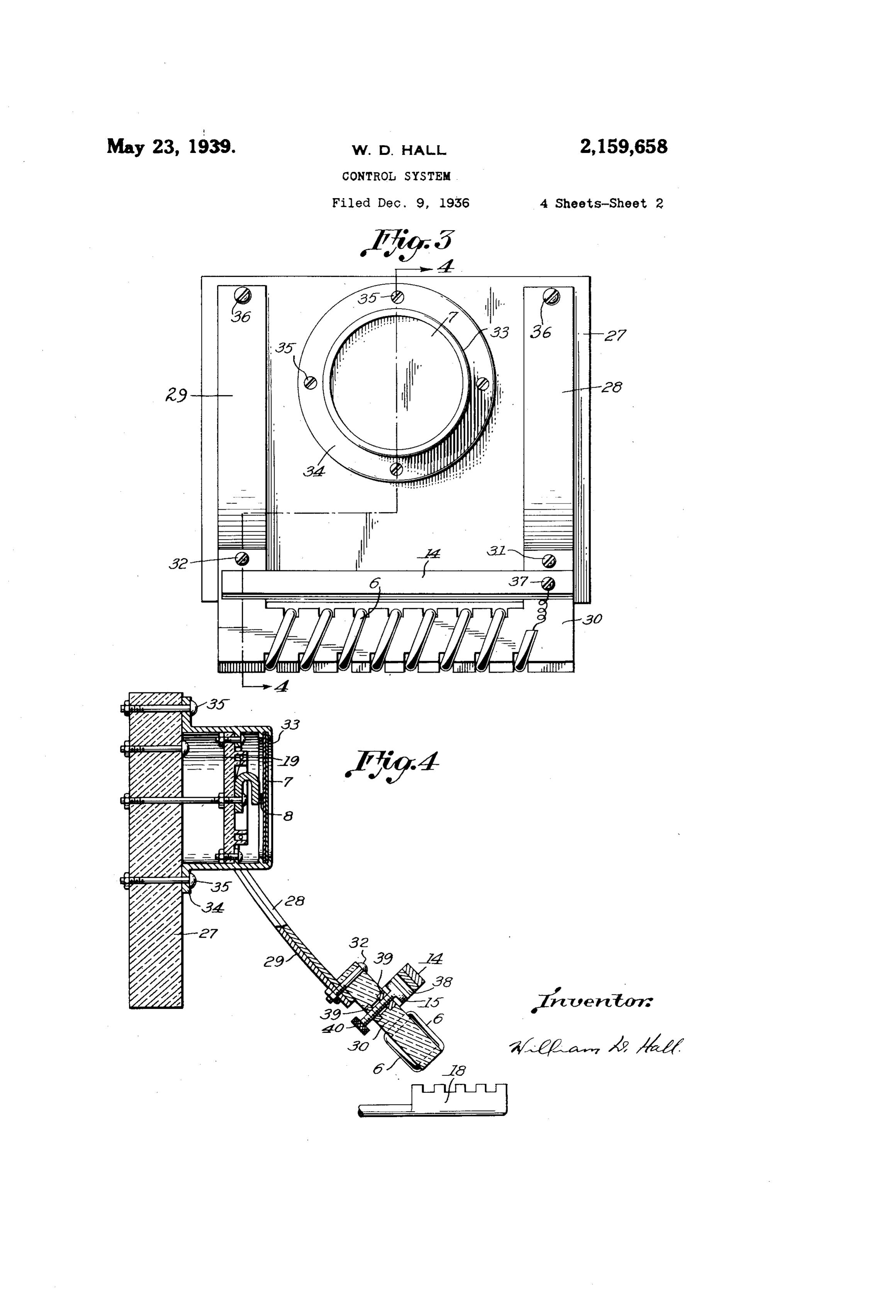
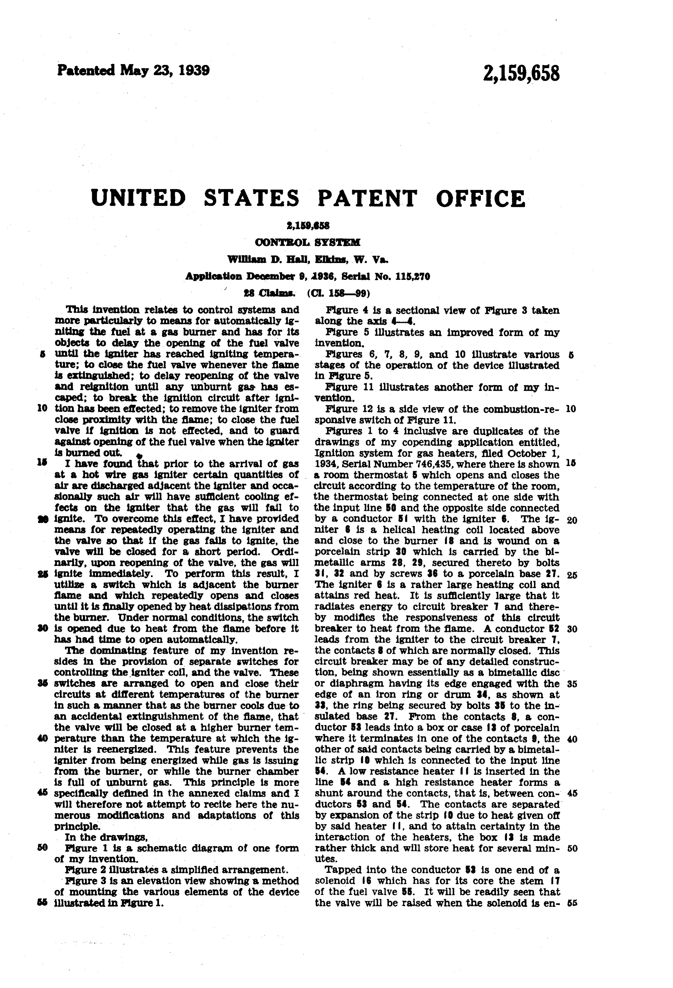
This invention relates to control systems and Figure 4 is a sectional view of Figure 3 taken more particularly to means for automatically ig along the axis 4-4.
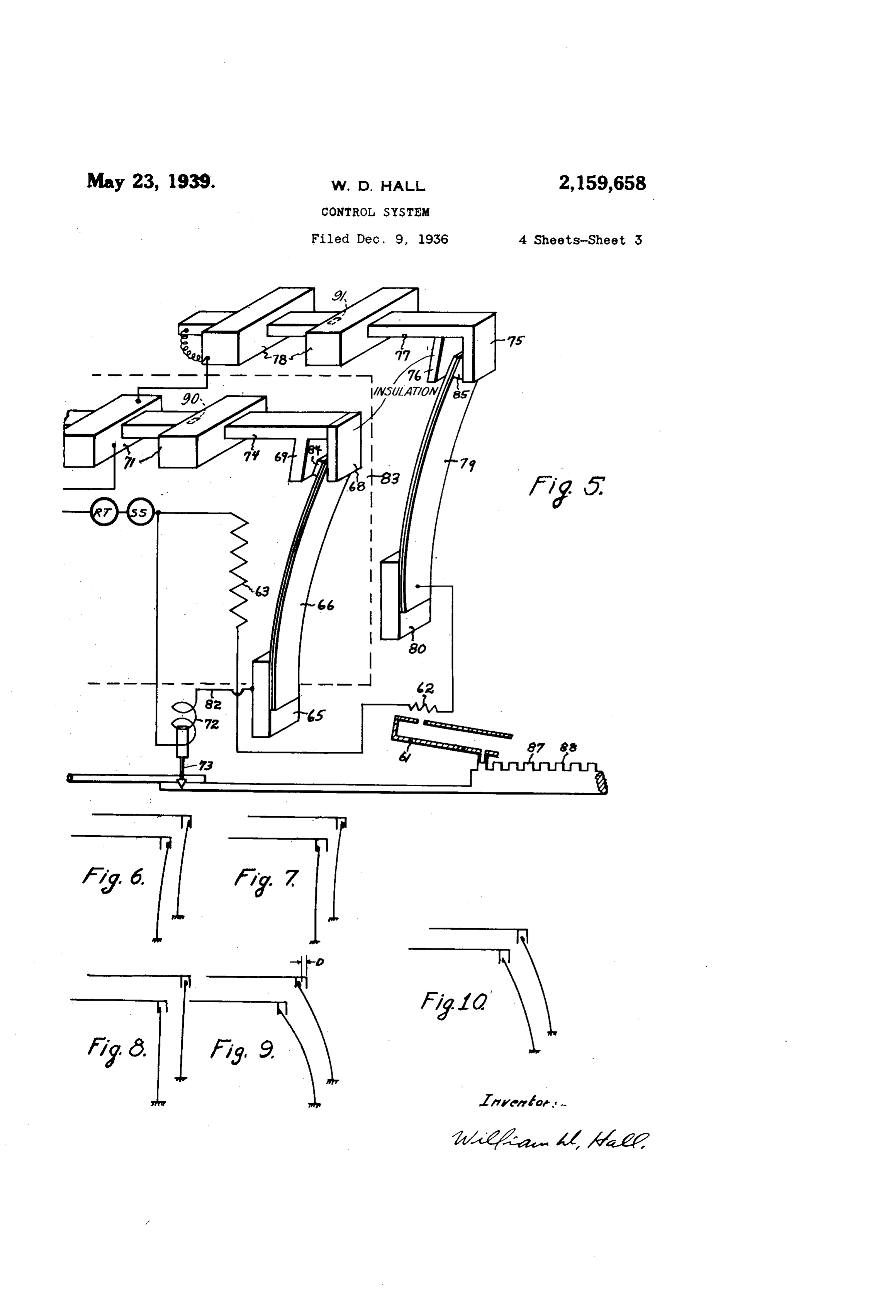
initing the fuel at a gas burner and has for its Figure 5 illustrates an improved form of my objects to delay the opening of the fuel valve invention, until the igniter has reached igniting tempera Figures 6, 7, 8, 9, and 10 illustrate various ture; to close the fuel valve whenever the fame stages of the operation of the device illustrated is extinguished; to delay reopening of the valve in Figure 5.
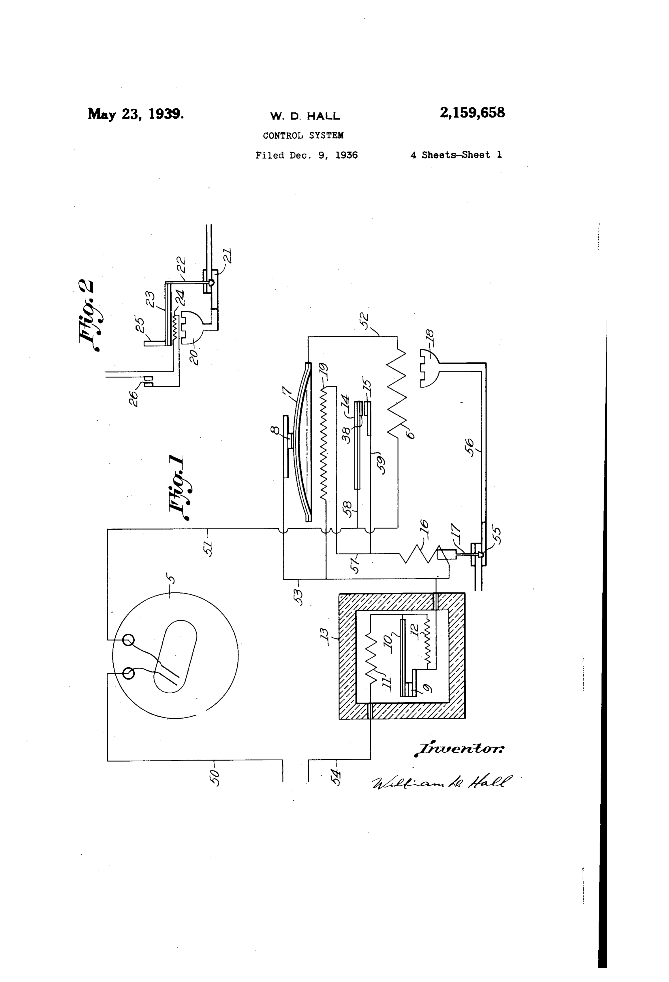
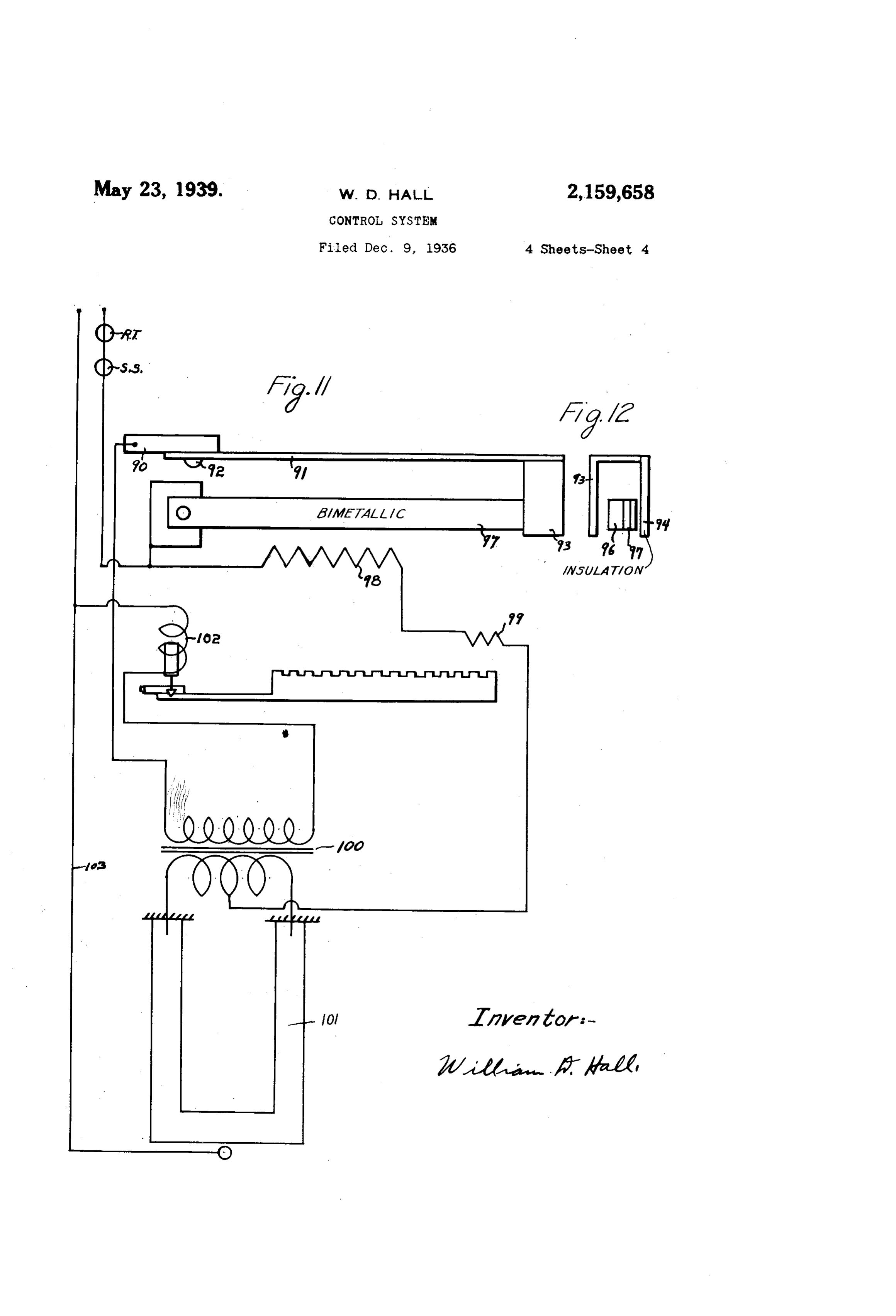
and reignition until any unburnt gas has es Figure 11 illustrates another form of my in caped; to break the ignition circuit after ign vention. - O tion has been effected; to remove the igniter from Figure 12 is a side view of the combustion-re O close proximity with the flame; to close the fuel sponsive switch of Figure 11, valve if ignition is not effected, and to guard Figures 1 to 4 inclusive are duplicates of the against opening of the fuel valve when the igniter drawings of my copending application entitled, is burned out. Ignition system for gas heaters, fled October 1, I have found that prior to the arrival of gas 1934, Serial Number 746,435, where there is shown at a hot wire gas igniter certain quantities of a room thermostat 5 which opens and closes the air are discharged adjacent the igniter and occa circuit according to the temperature of the room, sonally such air will have sufficient cooling ef the thermostat being connected at one side with fects on the igniter that the gas will fail to the input line 50 and the opposite side connected ignite. To overcome this effect, I have provided by a conductor 5 with the igniter 6. The ig 20 means for repeatedly operating the igniter and niter 6 is a helical heating coil located above the valve so that if the gas fails to ignite, the and close to the burner 8 and is wound on a Valve will be closed for a short period. Ord porcelain strip 30 which is carried by the bi narily, upon reopening of the valve, the gas will metallic arms 28, 29, secured thereto by bolts ignite in mediately. To perform this result, I 3, 32 and by screws 36 to a porcelain base 27. utilize a switch which is adjacent the burner The igniter 6 is a rather large heating coil and flame and which repeatedly opens and closes attains red heat. It is sufficiently large that it until it is finally opened by heat dissipations from radiates energy to circuit breaker 7 and there the burner. Under normal conditions, the switch by modifies the responsiveness of this circuit is opened due to heat from the flame before it breaker to heat from the fame. A conductor 52 30 has had time to open automatically. leads from the igniter to the circuit breaker 7, The dominating feature of my invention re the contacts 8 of which are normally closed. This sides in the provision of separate switches for circuit breaker may be of any detailed construc controlling the igniter coll, and the valve. These tion, being shown essentially as a bimetallic disc switches are arranged to open and close their or diaphragm having its edge engaged with the 35 circuits at different temperatures of the burner edge of an iron ring or drum 34, as shown at in such a nanner that as the barner cools due to 33, the ring being secured by bolts 35 to the in an accidental extinguishment of the flane, that sulated base 2. From the contacts 8, a con the valve will be closed at a higher burner ten ductor 53 leads into a box or case 3 of porcelain perature than the temperature at which the ig where it terminates in one of the contacts 9, the niter is reenergized. This feature prevents the other of said contacts being carried by a bimetal igniter from being energized while gas is issuing lic strip to which is connected to the input line from the burner, or while the burner chamber 5. A low resistance heater is inserted in the is full of unburnt gas. This principle is more line S4 and a high resistance heater forms a specifically defined in the annexed claims and E shunt around the contacts, that is, between con 45 will therefore not attempt to recite here the nu ductors 53 and 54. The contacts are separated merous modifications and adaptations of this by expansion of the strip to due to heat given of principle. by said heater , and to attain certainty in the In the drawings, interaction of the heaters, the box is made Figure 1 is a schematic diagram of one form rather thick and will store heat for several min 50
Figure 2 illustrates a simplified arrangement. Tapped into the conductor 5 is one end of a Figure 3 is an elevation view showing a method solenoid 6 which has for its core the stem f. of mounting the various elements of the device of the fuel valve 55. It will be readily seen that illustrated in Figure 1. the valve will be raised when the solenoid is en 55
Page 6
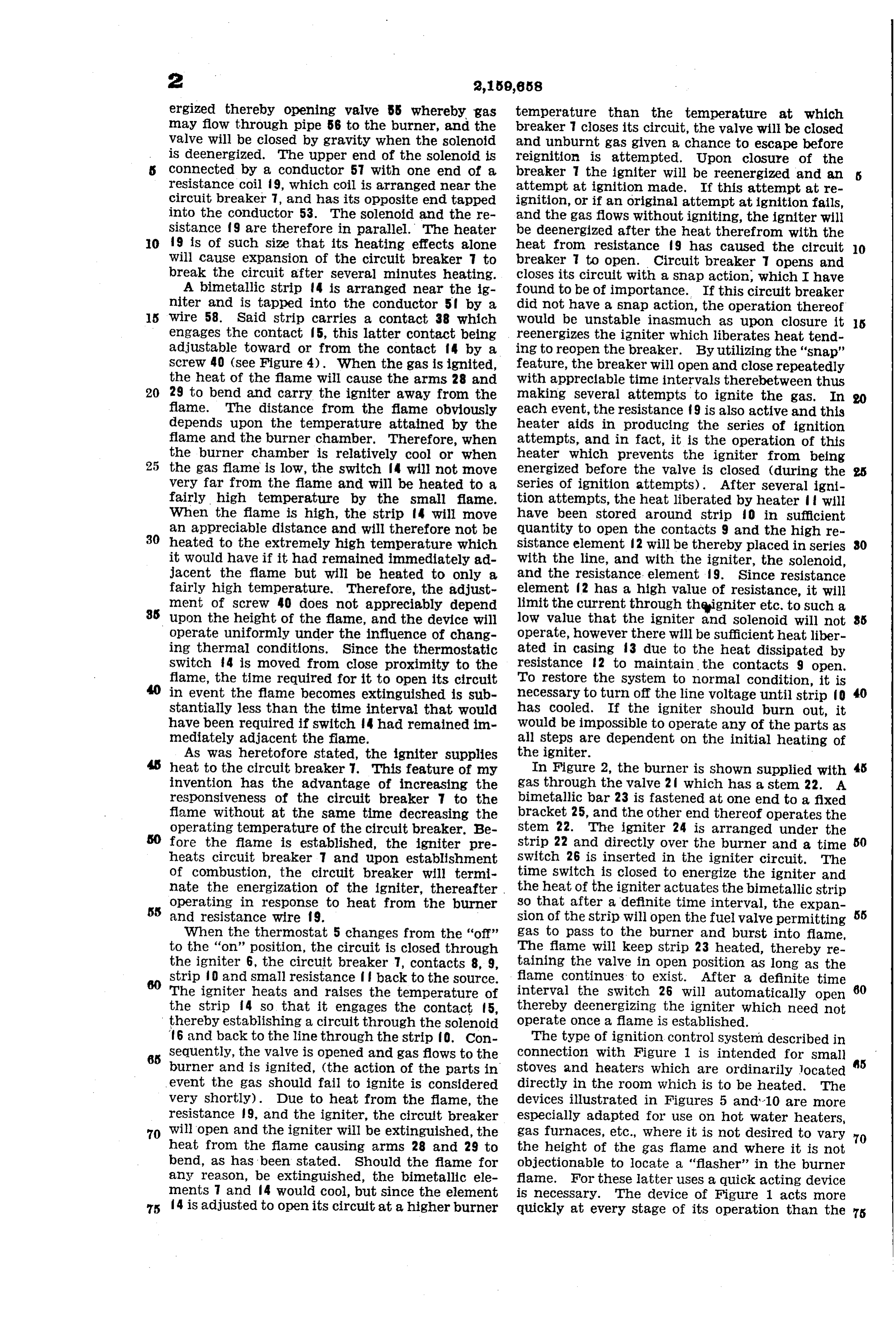
ergized thereby opening valve 55 whereby gas temperature than the temperature at which may flow through pipe 56 to the burner, and the breaker 7 closes its circuit, the valve will be closed Valve will be closed by gravity when the solenoid and unburnt gas given a chance to escape before is deenergized. The upper end of the solenoid is reignition is attempted. Upon closure of the connected by a conductor 57 with one end of a breaker the igniter will be reenergized and an resistance coil 9, which coil is arranged near the attempt at ignition made. If this attempt at re circuit breaker 7, and has its opposite end tapped ignition, or if an original attempt at ignition fails, into the conductor 53. The Solenoid and the re and the gas flows without igniting, the igniter will sistance f 9 are therefore in parallel. The heater be deenergized after the heat therefrom with the O 9 is of such size that its heating effects alone heat from resistance 9 has caused the circuit 0. will cause expansion of the circuit breaker 7 to breaker 7 to open. Circuit breaker T opens and break the circuit after several minutes heating. closes its circuit with a snap action, which I have A bimetallic strip 4 is arranged near the ig found to be of importance. If this circuit breaker niter and is tapped into the conductor 5 by a did not have a Snap action, the operation thereof 15 Wire 58. Said strip carries a contact 38 which would be unstable inasmuch as upon closure it 5 engages the contact fs, this latter contact being reenergizes the igniter which liberates heat tend adjustable toward or from the contact f by a ing to reopen the breaker. By utilizing the 'snap' screw 40 (see Figure 4). When the gas is ignited, feature, the breaker will open and close repeatedly the heat of the flame will cause the arms 28 and with appreciable time intervals therebetween thus 20 29 to bend and carry the igniter away from the making several attempts to ignite the gas. In flame. The distance from the fame obviously each event, the resistance 9 is also active and this depends upon the temperature attained by the heater aids in producing the series of ignition flame and the burner chamber. Therefore, when attempts, and in fact, it is the operation of this the burner chamber is relatively cool or when heater which prevents the igniter from being 25 the gas flame is low, the switch f will not move energized before the valve is closed (during the very far from the flame and will be heated to a Series of ignition attempts). After several igni fairly high temperature by the small flame. tion attempts, the heat liberated by heater will When the flame is high, the strip f4 will move have been stored around strip 0 in sufficient an appreciable distance and will therefore not be 30 heated to the extremely high temperature which quantity to open the contacts 9 and the high re sistance element 2 will be thereby placed in Series 30 it would have if it had remained immediately ad with the line, and with the igniter, the solenoid, jacent the flame but will be heated to only a and the resistance. element 9. Since resistance fairly high temperature. Therefore, the adjust element f2 has a high value of resistance, it will ment of screw 40 does not appreciably depend limit the current through thqigniter etc. to such a upon the height of the flame, and the device will low value that the igniter and Solenoid will not operate uniformly under the influence of chang operate, however there will be sufficient heat liber ing thermal conditions. Since the thermostatic ated in casing 3 due to the heat dissipated by switch 4 is moved from close proximity to the resistance 2 to maintain the contacts 9 open. flame, the time required for it to open its circuit To restore the system to normal condition, it is in event the flame becomes extinguished is sub necessary to turn off the line voltage until strip O 40 stantially less than the time interval that would has cooled. If the igniter should burn out, it have been required if Switch 4 had remained in WOuld be impossible to operate any of the parts as mediately adjacent the flame. all steps are dependent on the initial heating of As was heretofore stated, the igniter Supplies the igniter.
heat to the circuit breaker . This feature of my In Figure 2, the burner is shown supplied with 45 invention has the advantage of increasing the gas through the valve 2 which has a stem 22. A responsiveness of the circuit breaker to the bimetallic bar 23 is fastened at one end to a fixed flame without at the same time decreasing the bracket 25, and the other end thereof operates the operating temperature of the circuit breaker. Be stem 22. The igniter 24 is arranged under the fore the flame is established, the igniter pre strip 22 and directly over the burner and a time 50 heats circuit breaker T and upon establishment Switch 26 is inserted in the igniter circuit. The of combustion, the circuit breaker will termi time Switch is closed to energize the igniter and nate the energization of the igniter, thereafter . the heat of the igniter actuates the bimetallic strip
operating in response to heat from the burner so that after a definite time interval, the expan and resistance wire f 9. sion of the strip will open the fuel valve permitting 55 When the thernostat 5 changes from the 'off' gas to pass to the burner and burst into flame, to the "on' position, the circuit is closed through The flame will keep strip 23 heated, thereby re the igniter 6, the circuit breaker 7, contacts 8, 9, taining the valve in open position as long as the strip 0 and small resistance back to the source. flame continues to exist. After a definite time The igniter heats and raises the temperature of interval the switch 26 will automatically open 60 the strip 4 so that it engages the contact 5, thereby deenergizing the igniter which need not thereby establishing a circuit through the solenoid operate once a flame is established. 16 and back to the line through the strip O. Con The type of ignition control system described in 65 sequently, the valve is opened and gas flows to the connection with Figure 1 is intended for Small burner and is ignited, (the action of the parts in stoves and heaters which are ordinarily located s event the gas should fail to ignite is considered directly in the room which is to be heated. The very shortly). Due to heat from the flame, the devices illustrated in Figures 5 and 10 are more resistance 9, and the igniter, the circuit breaker especially adapted for use on hot water heaters, 70 will open and the igniter will be extinguished, the gas furnaces, etc., where it is not desired to vary 70 heat from the flame causing arms 28 and 29 to the height of the gas flame and where it is not bend, as has been stated. Should the flame for objectionable to locate a "flasher' in the burner any reason, be extinguished, the bimetallic ele flame. For these latter uses a quick acting device ments 7 and 4 would cool, but since the element is necessary. The device of Figure 1 acts more 75 4 is adjusted to open its circuit at a higher burner quickly at every stage of its operation than the 75
Page 7
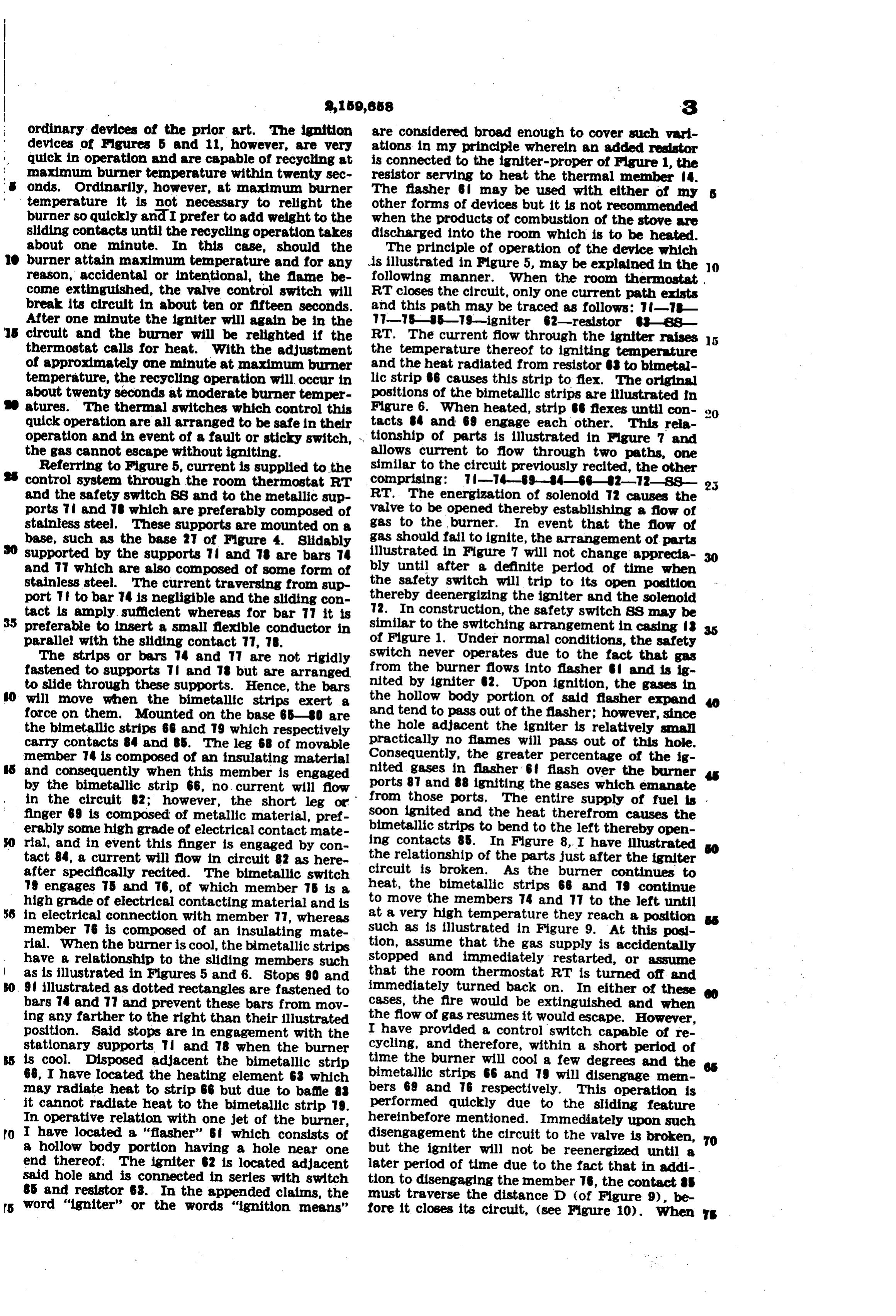
ordinary devices of the prior art. The ignition are considered broad enough to cover such vari devices of Figures 5 and 11, however, are very ations in my principle whereln an added resistor quick in operation and are capable of recycling at is connected to the igniter-proper of Figure 1, the maximum burner temperature within twenty sec resistor serving to heat the thermal member 4. onds, Ordinarily, however, at maximum burner The flasher may be used with either of any temperature it is not necessary to relight the other forms of devices but it is not recommended burner so quickly and I prefer to add weight to the when the products of combustion of the stove are sliding contacts until the recycling operation takes discharged into the room which is to be heated. about one minute. In this case, should the The principle of operation of the device which burner attain maximum temperature and for any is illustrated in Figure 5, may be explained in the O reason, accidental or intentional, the flame be following manner. When the room thernostat cone extinguished, the valve Control switch will RT closes the circuit, only one current path exists break its circuit in about ten or fifteen seconds. and this path may be traced as follows: -- After one minute the igniter will again be in the -S-S-79-igniter 2-resistor -SS circuit and the burner will be relighted if the RT. The current flow through the igniter raises 5 thernostat calls for heat. With the adjustment the temperature thereof to igniting temperature of approximately One minute at maximum burner and the heat radiated from resistor to bimetal temperature, the recycling operation will occur in lic strip B6 causes this strip to flex. The original about twenty seconds at moderate burner temper positions Of the bimetallic strips are illustrated fin atures. The thermal switches which control this Figure 6. When heated, strip B flexes until con 20 quick operation are all arranged to be safe in their tacts 4 and 69 engage each other. This rela operation and in event of a fault or sticky switch, , tionship of parts is illustrated in Figure 7 and the gas cannot escape without igniting. allows current to flow through two paths, one Referring to Figure 5, current is supplied to the similar to the circuit previously recited, the other control system through the room thermostat RT comprising: 7-4-9-84-6-2-2- SS and the safety switch SS and to the metallic sup RT. The energization of solenoid 2 causes the ports f and 8 which are preferably composed of valve to be opened thereby establishing a flow of stainless steel. These supports are mounted On a gas to the burner. In event that the flow of base, such as the base 2 of Figure 4. Slidably gas should fall to ignite, the arrangement of parts supported by the supports 7 and 78 are bars 74 illustrated in Figure 7 will not change apprecia and which are also composed of some form of bly until after a definite period of time when stainless steel. The current traversing from sup the safety switch will trip to its open position port f to bar 4 is negligible and the sliding con thereby deemergizing the igniter and the solenoid tact is amply sufficient whereas for bar 77 it is 72. In construction, the safety switch SS may be 35 preferable to insert a small flexible conductor in similar to the switching arrangement in casing 18 parallel with the sliding contact 77, 78. of Figure 1. Under normal conditions, the safety The strips or bars 74 and T are not rigidly switch never operates due to the fact that gas fastened to supports 7 and 78 but are arranged from the burner flows into flasher and is ig to slide through these supports. Hence, the bars nited by igniter 2. Upon ignition, the gases in will move when the bimetallic strips exert a the hollow body portion of said flasher expand force on them. Mounted on the base 65-80 are and tend to pass out of the flasher; however, since the bimetallic strips 66 and 79 which respectively the hole adjacent the igniter is relatively small carry contacts 84 and 85. The leg 68 of movable practically no flames will pass out of this hole. member 74 is composed of an insulating material Consequently, the greater percentage of the ig and consequently when this member is engaged nited gases in flasher 6 flash over the burner by the bimetallic strip 66, no current will flow ports 8 and 88 igniting the gases which emanate in the circuit 82; however, the short leg or from those ports. The entire supply of fuel is . finger 69 is composed of metallic material, pref Soon ignited and the heat therefrom causes the erably some high grade of electrical contact nate bimetallic strips to bend to the left thereby open rial, and in event this finger is engaged by con ing contacts 85. In Figure 8, I have illustrated tact 84, a current will flow in circuit 82 as here the relationship of the parts just after the igniter after specifically recited. The bimetallic switch circuit is broken. As the burner continues to 9 engages 5 and 76, of which member 5 is a heat, the bimetallic strips 66 and 79 continue high grade of electrical contacting material and is to move the members 74 and 77 to the left until SS in electrical connection with member 7, whereas at a very high temperature they reach a position member 76 is composed of an insulating mate such as is illustrated in Figure 9. At this posi rial. When the burner is cool, the bimetallic strips tion, assume that the gas supply is accidentally have a relationship to the sliding members such stopped and immediately restarted, or assume as is illustrated in Figures 5 and 6. Stops 90 and that the room thernostat RT is turned off and 9 illustrated as dotted rectangles are fastened to immediately turned back on. In either of these bars 7 and and prevent these bars from mov cases, the fire would be extinguished and when ing any farther to the right than their illustrated the flow of gas resumes it would escape. However, position. Said stops are in engagement with the I have provided a control switch capable of re stationary supports 7 and 78 when the burner Cycling, and therefore, within a short period of is cool. Disposed adjacent the bimetallic strip time the burner will cool a few degrees and the 66, I have located the heating element 63 which bimetallic strips 66 and 79 will disengage men may radiate heat to strip 66 but due to bafe 88 bers 69 and 76 respectively. This operation is it cannot radiate heat to the bimetallic strip 79. performed quickly due to the sliding feature In Operative relation with one jet of the burner, hereinbefore mentioned. Immediately upon such 70 I have located a 'flasher' 6 which consists of disengagement the circuit to the valve is broken, 70 a hollow body portion having a hole near one but the igniter will not be reenergized until a end thereof. The igniter 62 is located adjacent later period of time due to the fact that in addi said hole and is connected in series with switch tion to disengaging the member 76, the contact BS 85 and resistor 63. In the appended claims, the must traverse the distance D (of Figure 9), be 5 word "igniter' or the words "ignition means' fore it closes its circuit, (see Figure iO). When TS
Page 8
the igniter switch 85 recloses, resistor 63 will 1. In combination, a burner having means con raise the temperature of strip 66 until contact at trolling the feed of fuel thereto and an ignition 84 is remade. This latter action Will reopen the System comprising, an igniter, an electric heater, valve 73 and an attempt to relight the burner Will means controlled by heat from said igniter for 5 be made as heretofore stated. energizing said heater, and thermostatic means It is specifically pointed out that the sliding operatively associated with said heater and burner feature is a Substantial improvement OVer a con for controlling energization of said igniter. trol system in which members 74 and T7 do not 2. In combination, a burner, a circuit includ move. However, this improvement should not ing means for permitting the flow of fuel to O act as a limitation to my broader claims as such Said burner when the circuit is closed and pre O are clearly of sufficient scope to cover the simple, venting said flow when the circuit is open, and a yet effective, system wherein contact members 4 control System comprising ignition means, a and are stationary. In fact, my principle is thermal switch responsive to combustion which even broader than electrical circuit arrangements OpenS When heated and closes when cooled in 5 Specifically recited above, and rather than at Series with and controlling energization of said s tempt to list the numerous modifications which ignition means, and a thermal switch responsive I have experimented upon and conceived, I am to both the heat of combustion and the heat from defining the principle in the appended claims. Said ignition means which closes when heated he control System of Figure illustrates and Opens when cooled in series with and con 20 an improved form of sliding contact, in which the trolling the energization of said circuit; said ther 20 contacts rotate. Member 9 is pivoted to support mal Switches being so constructed and arranged 90 by means of the pivot 92. Bimetallic Strip that as the burner cools the second thermal 97 is solely and rigidly supported at its left end SWitch Will open before said first thermal switch and moves the rotatable structure with its free recoSeS.
25 end. The metalic member 9 carries the insul 3. In a burner control system, in combination, s lating member 94 and the metallic contact 93. a burner, ignition means having an electric cir When the burner temperature is falling, the strip cuit for energizing the same, thermostatic means 97 engages insulating member 94, whereas as the for breaking said circuit responsive to heat, an burner temperature is increasing, the contacts electric heater operatively associated with said 30 93 and 96 are in engagement. Operatively re thermoStatic means, and a circuit including 30 lated with strip 97 and in series with igniter 99, means for permitting a flow of fuel to said burner I have connected the heating element 98. The and for preventing said flow and having a heatre thermal SWitch. 9 is aSSociated. With the burner Sponsive circuit closer therein which closes in flame, however, I prefer not to associate thermal response to heat from said ignition means; said 35 Switch f) with the heat from the burner. This electric heater being connected to said fuel control latter thermal switch is heated by passage of cur circuit whereby heat from the ignition means will rent therethrough from the current transformer establish a flow of fuel and heat from said heater 0. The contacts of thermal Switch 0 are Will break the ignition circuit.
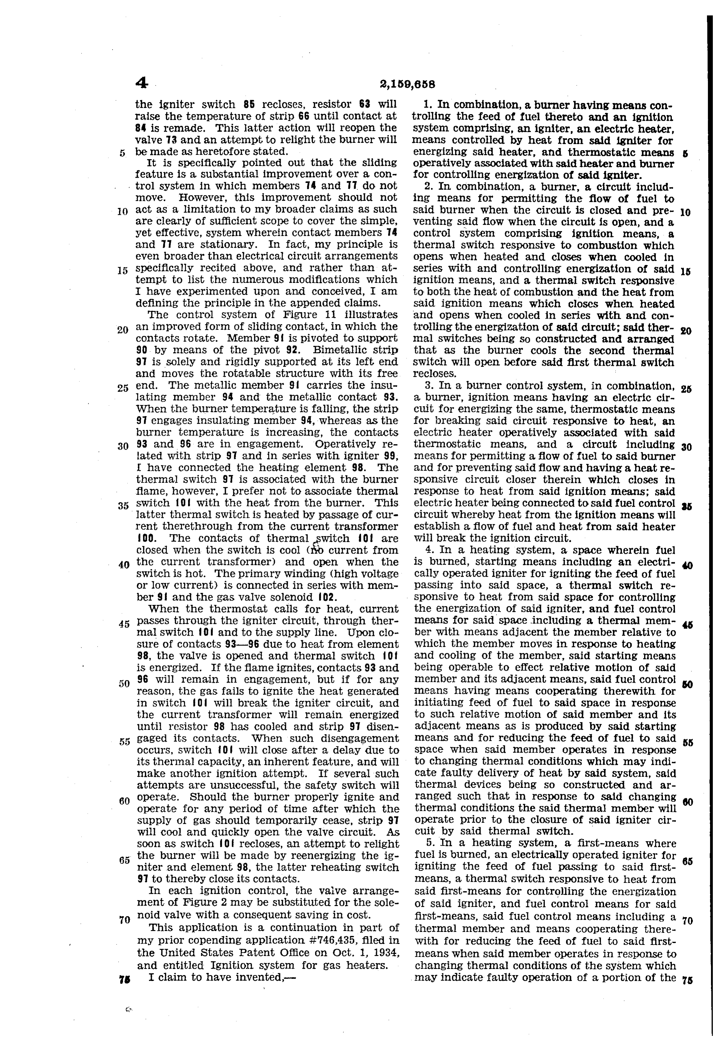
closed. When the SWitch is cool ( current from 4. In a heating System, a space wherein fuel 40 the current transformer) and open when the is burned, starting means including an electri Switch is hot. The primary winding (high voltage cally Operated igniter for igniting the feed of fuel or low current) is connected in series with men paSSing into said space, a thermal switch re ber 9 and the gas valve Solenoid O2. Sponsive to heat from said space for controlling When the thermostat calls for heat, current the energization of said igniter, and fuel control 45 passes through the igniter circuit, through ther means for said space including a thermal mem mal switch 0 and to the supply line. Upon clo ber with means adjacent the member relative to sure of contacts 93-96 due to heat from element which the member moves in response to heating 98, the valve is opened and thermal switch Of and cooling of the member, said starting means is energized. If the flame ignites, contacts 93 and being Operable to effect relative motion of said 96 will remain in engagement, but if for any member and its adjacent means, said fuel control reaSOn, the gas fails to ignite the heat generated means having means cooperating therewith for in Switch O will break the igniter circuit, and initiating feed of fuel to said space in response the current transformer Will remain energized to Such relative motion of said member and its until resistor 98 has cooled and strip 9 disen adjacent means as is produced by said starting gaged its contacts. When such disengagement Inleans and for reducing the feed of fuel to said 5 occurs, Switch foll will close after a delay due to Space When Said member operates in response its thermal capacity, an inherent feature, and will to changing thermal conditions which may indi make another ignition attempt. If several such cate faulty delivery of heat by said system, said attempts are unsuccessful, the safety switch will thermal devices being so constructed and ar 60 operate. Should the burner properly ignite and ranged Such that in response to said changing operate for any period of time after which the thermal conditions the said thermal member will Supply of gaS should temporarily cease, strip 9. Operate prior to the closure of Said igniter cir Will cool and quickly Open the valve circuit. As cuit by said thermal switch. Soon as switch 0 recloses, an attempt to relight 5. In a heating System, a first-means where 65 the burner will be made by reenergizing the ig fuel is burned, an electrically operated igniter for 65 niter and element 98, the latter reheating Switch igniting the feed of fuel passing to said first 97 to thereby close its contacts. means, a thermal Switch responsive to heat from In each ignition control, the waive arrange said first-means for controlling the energization ment of Figure 2 may be substituted for the Sole of Said igniter, and fuel control means for said 70 noid valve with a consequent saving in cost. first-means, said fuel control means including a 70 This application is a continuation in part of thermal member and means cooperating there my prior copending application #746,435, fled in With for reducing the feed of fuel to said first the United States Patent Office on Oct. 1, 1934, means when said member operates in response to and entitled Ignition System for gas heaters. changing thermal conditions of the system which s I claim to have invented may indicate faulty operation of a portion of the s
Page 9
system, said thermal devices being so constructed and arranged such that in response to said chang lated with the burner for controlling the feed of fuel thereto to permit a flow of fuel while ing thermal conditions the said thermal member said thermal means is expanding and to pre will operate prior to the closure of the igniter vent said flow when said thermal means changes circuit by said thermal switch and thereafter said from an expanding motion to a contracting mo thermal devices will, alternately operate there tion, an igniter having an electric circuit for ener by recycling the system. gizing the same, said circuit having means coop 6. In a heating system, in combination, a space erating therewith for heating said thermal means, wherein gas may be burned, an electrical igniter 10 for initiating combustion of the gas to be burned, and an expansible and contractable thermal means operatively related with the burner flame O a circuit breaker controlling the operation of said for controlling the energisation of said igniter igniter, a thermal element close to said circuit breaker for Operating the same to open the cir circuit to open said circuit when said last-means cuit breaker when combustion is established and begins to expand and to reclose said igniter cir 5 to reclose the circuit breaker if combustion ac cuit after said last-means has contracted a short
cidentally extinguishes for a period of time, a wall 10. In combination, a burner and a control separating said space and said circuit breaker system therefor comprising a circuit including thereby insulating said circuit breaker from direct an igniter for the burner, means responsive to contact with the products of combustion, whereby combustion and to a current flow through said the said wall inherently also increases the time circuit to establish a flow of fuel to said burner lag of response of said circuit breaker to ten and to prevent said flow of fuel, and means re perature changes of said space, means, for re sponsive to combustion for breaking said igniter ducing said increased time lag of response by circuit when combustion is established . and to modifying the quantity of energy which said reclose said igniter circuit when combustion thermal element would ordinarily otherwise re ceases, said first and second mentioned means 25 ceive, and fuel control means comprising a ten being so constructed and arranged such that perature responsive actuator which operates in as the burner cools due to extinguishment of response to predetermined changing thermal con the flame the first mentioned means will stop ditions of the heating system to reduce the feed the flow of fuel to said burner before the ignition of fuel to said space in response to a fault of circuit is reclosed by said second mentioned the system, said actuator and said circuit breaker e.S.
being so constructed and arranged that in re 11. In a burner control system, a burner, an sponse to continuance of the fault which caused igniter for the burner, a circuit including said initial operation of said actuator the said actuator igniter means for breaking said circuit respon and said circuit breaker will operate in such a sive to heat, means responsive to an energiza 35 manner as to attempt to relight the fuel with tion of said circuit and to combustion to heat said actuator initially operating first. said circuit breaking means, and means operated 7. In a heating system, in combination, a heat by said second mentioned means for controlling er where gas may be burned, an igniter for ini the feed of fuel to said burner. tiating combustion of the gas to be burned, a 12. In an ignition system, an igniter, a circuit 40 heat responsive circuit controlling device which breaker in the igniter circuit, said circuit break deemergizes the igniter in response to heat from er including a heat responsive element which said heater and energizes the igniter when the snaps temperature of said heater falls below a prede cooled open when heated and snaps closed when below a predetermined temperature and termined point, and a device for reducing the is responsive time lag of response of said circuit breaker con and the flame to heat from the igniter circuit 45 prising means which when energized reduces the fails to ignite to such a degree that if the flane the heat from the igniter circuit heat transfer rate from said heater to said cir will repeatedly open and close said circuit break cuit breaker, and a switch which receives heat er with appreciable time intervals between sub from said heater and is arranged to open and de sequent openings and closures. 50 energize said means when the temperature of 13. In combination, a burner, and an ignition said heater falls below a predetermined point. system comprising an igniter having an electrical 8. A device which is adapted to be placed ad circuit for energizing the same, a fuel circuit jacent a burner to control the operation thereof including means for permitting a flow of fuel to comprising a circuit including means for heat said burner and for preventing said flow, a ther 5 ing a portion of the fuel to the ignition ten mal switch in said fuel circuit which is responsive perature, a switch responsive to combustion to to heat from the ignition circuit and the burner, open said circuit upon establishment of combus and a second thermal switch which is responsive tion and to reclose said circuit when combustion to heat from the burner flame to break the igniter ceases, a circuit including means for permitting circuit. v 60 a flow of fuel to said burner and for prevent 14. A control system comprising a burner, an ing said flow, a switch controlling said fuel con igniter therefor, a circuit for said igniter a heat trol circuit which responds to a passage of cur responsive circuit breaker in the igniter circuit rent through said ignition circuit to start a flow which opens when heated and closes when cooled, of fuel and also responds to combustion to re said circuit breaker being positioned adjacent 65 tain a flow of fuel during periods of satisfac the burner flame, and means for opening and re tory combustion and which stops the flow of fuel closing said circuit breaker if combustion fails when combustion ceases, said switches being so constructed and arranged such that as the burn to 15. be established on the first effort. In combination, a burner, a thermal men er cools due to extinguishment of the flane said 70 second-mentioned switch will operate to stop ber adjacent said burner and responsive to heat 70 therefrom, means operated by said thermal men said flow of fuel before said ignition circuit is ber for controlling the feed of fuel to said burner reclosed by said first-mentioned switch. to initiate said flow when the temperature of 9. In combination, a burner, and a control the said thermal member increases from its nor
system comprising thermal means operatively re mal room temperature and to prevent said flow 5
Page 10
when said thermal member has cooled below a igniter, stopping the supply of fuel in event it predetermined temperature, an electric heater fails to ignite, and immediately reestablishing a positioned in heat transfer relationship with Said flow of fuel.
thermal member, a portion of Said heater being 22. In combination, a burner, an electrical 5 in igniting relationship with said burner and heating device including a fuel igniting portion adapted upon energization to ignite the fuel, andassociated with said burner, and thermal means a second thermal member which operates inde responsive to the heat of combustion at said pendently from said first thermal member and burner for controlling the flow of fuel thereto and controls the energization of said electric heater the energization of said heating device, at least a O to close the circuit thereto when the burner cools pertion of said thermal means being associated 0 and open the circuit after the burner has be with at least a portion of said heating device come heated, said second thermal member bear and SO arranged that heat from said heating ing positioned adjacent said burner but not in device affects said thermal means to establish mediately adjacent said electric heater, whereby said flow of fuel, said thermal means being so the second thermal member is not operated pri constructed and arranged that when combus 5 marily by said heater, said thermal members be tion is established the heat thereof will affect ing so constructed and arranged such that as the said thermal means to deenergize said heating burner cools the said first thermal member will device and When the burner flame accidentally operate to discontinue the feed of fuel before extinguishes due to a temporary cessation of the 20 said second thermal member recloses the igni fuel Supply the said thermal means Will stop the 20 tion circuit. flow of fuel and after an appreciable interval of 16. A device responsive to the heat generated time to permit unburnt gas to escape reenergize by a heat generator comprising, thernostatic said heating device and reestablish a flow of fuel, means, means actuated thereby, and means re whereby to relight the burner. sponsive to the temperature attained by Said 23. The device set forth by claim 2 character S25 heat, generator for varying the heat transfer re ized by a Support for Said ignition means and lation between said heat generator and Said ther Said Second thermal switch, said ignition means nostatic means. consisting of a coil of resistance Wire wound on 17. A device responsive to the heat generated Said support, and means for controlling the rela by a heat generator comprising, thermostatic tive position of said support and the burner to 30 means, means actuated thereby, and Supporting maintain said support in close proximity to said means for said thermostatic means, Said Sup burner in absence of combustion and in a posi porting means constituting a bimetallic Strip re tion near but a short distance away from the sponsive to heat from the heat generator and burner in response to combustion of fuel at said 3 5 carrying said thermostatic means toward Or away burner, whereby to enable Said igniter and ther from the heat generator. mal member to be close to and in good heat trans 18. In a heating system, in combination, a. fer relationships with the burner prior to com burner, an electric igniter for initiating combus bustion as well as to enable a lower operating tion of the fuel from said burner, means includ temperature of the igniter and thermal member - 0 ing a thermal actuator operable to maintain said during Combustion than would be the case if the 40 igniter deemergized or energized in response to Sepport remained closely related to said burner. the presence or absence of combustion respecs 24. In a heating System, a main fuel burning tively, a thermally movable support on which heater, thermal means responsive to heat from said actuator is mounted, said support being posi Said main fuel burning heater and operable to tioned adjacent said burner and operable to move affect the flow of fuel thereto, and additional 45 said actuator toward or away from Said burner means including a thermal member affected by according as the temperature thereof is decreas the heat of combustion of said main fuel burning ing or increasing, to thereby maintain Said ac tuator at a predetermined maximum temper heater, Said additional means being operable in response to heating of said thermal member by ature during combustion and enable a reduced Said main fuel burning heater to reduce the heat SO time lag of response of said actuator When com transfer relationship from said main fuel burn bustion ceases. ing heater to said first-named thermal means, 19. In a heating System, in combination, a Whereby during normal operation of the System burner, a circuit controlling the feed of fuel the first-named thermal means does not reach as thereto, a thermal switch in said circuit for clos high a temperature as it would reach in absence SS ing the circuit when heated and opening the cir of said last-recited means. cuit, when cooled, and a thermally movable Sup 25. In a heating System, a main fuel burning port on which said Switch is mounted, said Sup heater, electrically operated means having a port being positioned adjacent said burner and thermal Switching mechanism which is respon 80 operable to move said Switch toward or away to heat from Said main fuel burning heater 60 from said burner according as the temperature sive thereof is decreasing or increasing, to thereby for controlling the operation of said electrically Operated means, Said electrically operated means enable a reduced time lag of response of Said including an electrical igniter for said main fuel thermal Switch when combustion ceases.
65 20. A device as defined by claim 8 including burning heater, and thermal means which re additionally, an energy integrating device con ceives heat from said main fuel burning heater nected to said first-mentioned circuit, and means and affects the flow of fuel thereto, said elec responsive to the energy integrated by said de trically operated means including means for af vice for deenergizing said second-mentioned cir fecting the temperature of said last-named ther 70 cuit in event the energy integrated by said de mal means to a greater extent than it affects 70 vice exceeds a predetermined relationship. the temperature of the thermal switching mech 21. The method of utilizing an igniter of the anism.
hot-member type to establish combustion of fuel 26. In a heating system; the combination with at a burner which includes heating the igniter, a main fuel burning heater of control means co is subsequently establishing a flow of fuel at the Operating with Said heater operable to establish S
Page 11
combustion of fuel thereat and including an ar contacts in response to heat of combustion of rangement whereby first and second efforts to said fuel at said fuel burning heater. establish combustion of fuel at Said heater may 27. In a heating system, a main fuel burning be made with the second effort following the heater, a fuel feed line to said heater, means ad first with a short time interval of separation; jacent to and cooperating with said fuel feed said control means comprising means affecting line to affect the feed of fuel therethrough, wires the flow of fuel to said fuel burning heater in adapted for connection to a source of electrical such a manner that when more than one effort is supply, and a control system including the foll made to establish combustion of fuel at said lowing parts all located solely and completely O heater that fuel flows to said heater during said within proximity of said fuel burning heater and 10 efforts and is stopped and restarted between affected by heat therefrom, an electrically oper efforts; an electrical resistance igniter operatively ated resistance igniter wound for operation at related with said main fuel burning heater; and the potential of Said Wires, a thernal Switch di means, including contacts directly in series with rectly in series with said igniter and said wires 5 said igniter, actuated by said fuel-affecting for deenergizing said igniter in response to com 5 means as well as by combustion conditions to bustion, and a thermal member for controlling open said contacts upon establishment of com Said first-named means.
bustion and when more than one effort is made 28. The device defined by claim 13 including to establish combustion at said fuel burning additionally an electrical heating resistor con 20 heater to Open and close said contacts between trolled by said first-named thernal switch and 20 efforts, said last-named means including a ther energized concurrently with flow of fuel to said mal member located responsive to combustion burner, said heating resistor being in heat trans as well as near to said contacts and arranged fer relation with said second thermal switch. such that said member operates to separate said WILLIAM D. H.A.
Provenance
- Collection
- Cited prior art
- Original PDF
- patentimages.storage.googleapis.com →
- Filed
- 1936-12-09
- Pages
- 11
- Method
- pdftotext (the PDF's own text layer) + pdftoppm 300dpi page scans
- Source
- Google Patents bibliographic record
- Granted
- 1939-05-23
- Inventors
- William D Hall
- Transcribed from
- patentimages.storage.googleapis.com →