patent · US4043308
Control of the initiation of combustion and control of combustion
23 August 1977
Page 1 — bibliographic record
United States Patent (19) (11) 4,043,308 Cerkanowicz 45) Aug. 23, 1977 54 CONTROL OF THE INITIATION OF 58) Field of Search ........................... 431/1, 6, 2,254; COMBUSTON AND CONTROL OF 60/39.82, 39.06, 274; 123/143; 250/432, 435, COMBUSTON 436; 204/162 75 Inventor: Anthony E. Cerkanowicz, Livingston, (56) References Cited N.J. U.S. PATENT DOCUMENTS 73 Assignee: Photochem Industries, Inc., Fairfield, 3,122,887 3/1964 Farmer ............................ 60/39.82 R N.J. 3,560,363 2/1971 Goetz ............................... 204/162 R 3,937,967 2/1976 Steinitz ................................. 250/.435 (21) Appl. No.: 680,867 Primary Examiner-Edward G. Favors 22 Filed: Apr. 27, 1976 Attorney, Agent, or Firm-Cooper, Dunham, Clark, Griffin & Moran
Related U.S. Application Data 57 ABSTRACT 62) Division of Ser. No. 468,543, May 9, 1974. Method and apparatus for controlling the initiation and completion of self-sustaining combustion in fuel/oxi 51 int. C.’............................................... F23H5/20 dizer mixtures through the use of ultraviolet radiation 52 U.S. C. ............................... 123/143 R; 60/39.06; absorbed throughout the mixture.
A ZZZZZZZZZ
Page 2
Drawing sheet — no readable text.
Page 3
Drawing sheet — no readable text.
Page 4
Drawing sheet — no readable text.
Page 5
The present invention also utilizes the irradiation of a
CONTROL OF THE NITATION OF combustible mixture from a plurality of sources of ultra COMBUSTION AND CONTROL OF violet energy, thereby enhancing the photochemical COMBUSTON combustion process. By the use of such plural sources, This is a division of application Ser. No. 468,543, filed 5 it has been found that different zones within a combusti May 9, 1974. ble mixture may be preconditioned and the combustion
BACKGROUND AND BRIEF DESCRIPTION OF
processes therein controlled to enhance the combustion
THE INVENTION
process of the overall mixture.
The invention contemplates unique sources of ultravi
This invention relates to methods and apparatus for O olet energy in the form of spaced electrodes in an inert controlling the initiation and completion of combustion gas atmosphere. In one embodiment a window is em in combustible mixtures. The invention has particular ployed to provide for the transmission of ultraviolet application and is directed to the photochemical control energy from a sealed source, without appreciable ab of the initiation and completion of combustion, particu 5 sorption thereof, into a combustible mixture. In another larly in fuel/oxygen/diluent combustible mixtures. embodiment, a 37 windowless' source is employed Conventionally, combustible mixtures are ignited by utilizing a flow of inert gas to dynamically create the raising the temperature of a zone within such a mixture necessary gaseous conditions between the electrodes, to the thermalignition point, so that ignition is initiated displacing foreign gas, and thus providing for efficient in the zone and is then propagated throughout the mix generation of the necessary ultraviolet radiation. ture. Thermal ignition temperatures of conventional 20 bustion The present invention thus has application to all com mixtures are relatively high, and at such high tempera processesprocesses, and in particular to those combustion involving oxygen, e.g., combustion processes tures pollutants are formed. Further, the creation of in pollutants in the normal mixture range has been found be automotive and aircraft engines. The techniques may employed in enhancing combustion in all combustion to decrease with decreasing proportions of fuel in the 25 chambers, mixture, so that fuel-lean mixtures generate less pollut devices. including exhaust systems of combustion ants.
The present invention involves the appreciation that calThe work to date in the investigation of photochemi the irradiation of a combustible mixture with photon theoretical. of control the combustion process has largely been
Representative publications are as follows:
energy in the ultraviolet range preconditions the mix 30 1. "Final report - Photochemical Enhancement of ture by the photodissociative creation of a combustion Combustion and Mixing in Supersonic Flows, " by intermediary species. For example, in the case of a fuel A. E. Cerkanowicz, Photochem Industries, Inc., Moxygen mixture, additional oxygen atom concentra Fairfield, N.J., dated Nov. 1973, distributed on Apr. tions are photochemically created far in excess of those 1, 1974.
existing at the temperature of the mixture. Such concen 35 2. "Interim Scientific Report - Photochemical En trations of combustion intermediary species in the mix hancement of Combustion and Mixing in Super ture result in the effective lowering of the thermal igni sonic Flows," by A. E. Cerkanowicz, Photochem tion temperature of the mixture and also permit com Industries, Fairfield, N.J., dated March 1972, dis bustion with greatly reduced proportions of fuel and at tributed on May 16, 1973. greatly reduced pressures. Further, such ultraviolet 40 3. "Photochemical Ignition and Combustion En irradiation has been found to affect the reaction front hancement in High Speed Flows of Fuel-Air Mix propagation velocity and decrease ignition delay, All of tures,' by A. E. Cerkanowicz and R. F. McAlevy these factors enhance the combustion process and re III, Photochem Industries, Incorporated, Fairfield, duce pollutants generated. New Jersey, published by American Institute of Photochemical control of the combustion process is 45 Aeronautics and Astronautics at AIAA 11TH preferable to the conventional control by spark or other AEROSPACE SCIENCES MEETING, WASH sources such as glow discharge, exploding wire, hot INGTON, D.C./Jan. 1-12, 1973, AIAA Paper No. wire, and the like. In particular, initiation of the com 73-216.
bustion process by these conventional devices does not 4. "The Photochemical Ignition Mechanism of Un readily offer a means for controlling the rate of combus 50 sensitized Fuel-Air Mixtures,' by A. E. Cerkanowicz, tion or flame propagation speed as does photochemical M. E. Levy and R. F. McAlevy III, Photochem Indus control. tries, Fairfield, New Jersey, published by American In the present invention, the photoconductive cre Institute of Aeronautics and Astronautics at AIAA ation of a combustion intermediary species may be in a 8TH AEROSPACE SCIENCES MEETING, NEW concentration below that required for the photochemi 55 YORK, NEW YORK/Jan. 19-21, 1970, AIAA Paper cal initiation of combustion at the temperature of the No. 70-149.
mixture but above the concentration of the species that 5. "Argon Photoionization Cross-Sections and Aut would exist at the thermal ignition temperature of the oionized Line Profiles in the 584-304 A Region,' by M. mixture. In this fashion, the mixture is preconditioned E. Levy, Photochem Industries, Hoboken, N.J., 07030, so that the thermal ignition temperature is singificantly 60 and R. E. Huffman, Air Force Cambridge Research lowered and the mixture is closer to combustion. Fol Laboratories, Bedford, Massachusetts 01731, published lowing the preconditioning, combustion may be initi by Pergamon Press 1969 in J. QUANT, SPECTROSE, ated by irradiating the mixture with a superimposed RADIAT, TRANSFER, Vol. 9, pp. 1349-1358, ultraviolet flash of sufficient intensity to initiate com Printed in Great Britain, bustion therein. Alternatively and as another example, 65 6. "Ignition of Subatmospheric Gaseous Fuel-Oxidant the preconditioning of the mixture may be followed by Mixtures by Ultraviolet Irradiation,' by M. E. Levy a superimposed electrical spark discharge therein or by and A. E. Cerkanowicz, Vitro Laboratories, West some other heating method to initiate combustion. Orange, New Jersey and R. F. McAlevy III, Stevens
Page 6
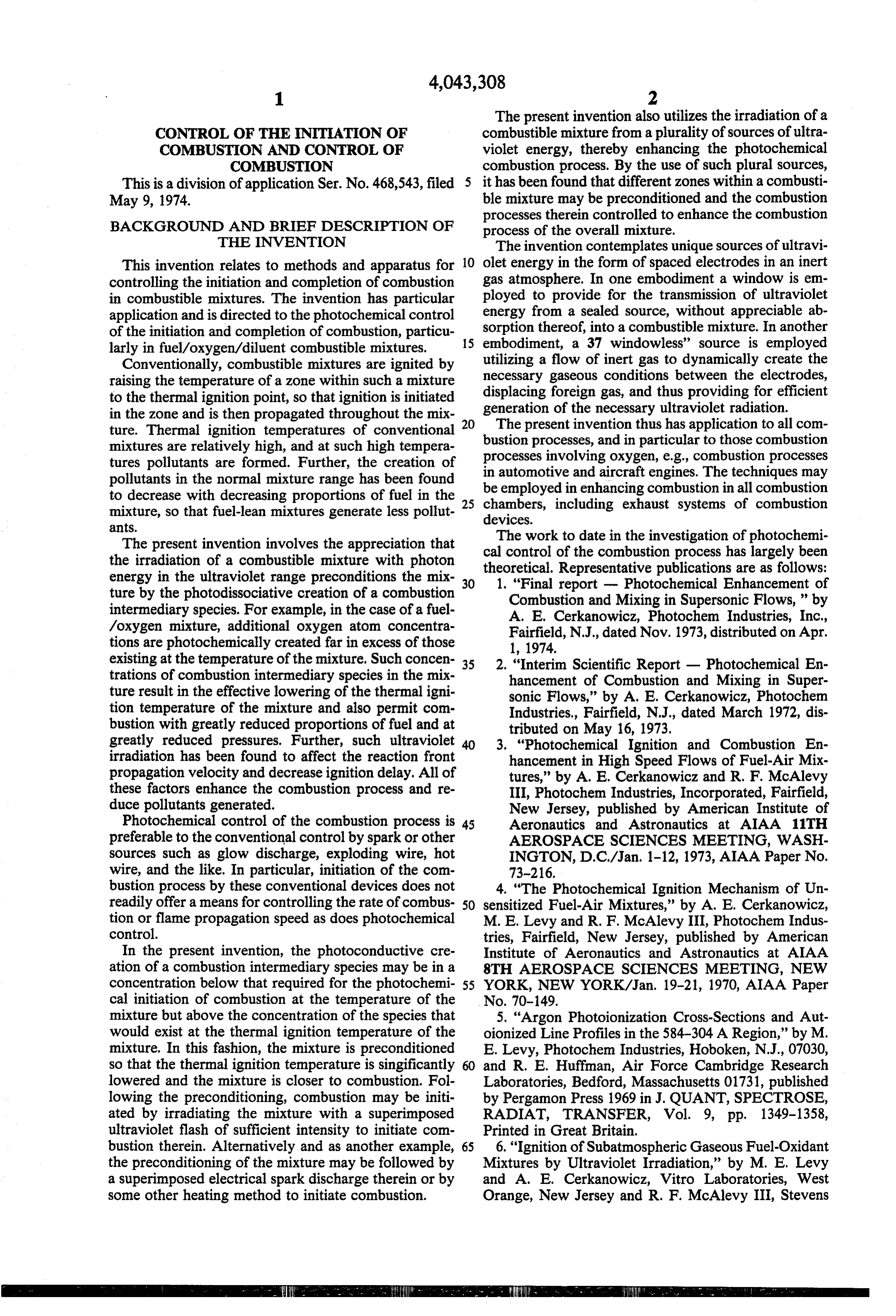
Institute of Technology, Hoboken, New Jersey, pub lished by American Institute of Aeronautics and Astro The mixture which is irradiated may or may not be nautics at AIAA 7TH AEROSPACE SCIENCES intermixed fully or partially with a diluent; for example, MEETING, NEW YORK CITY, NEW YORK/Jan. in the case of fuel/air as the combustible mixture, nitro 20-22, 1969, AIAA Paper No. 69-88. gen is typically present as a major diluent. 7. "Photochemical Ignition of Low Pressure Fuel As noted above, the present invention involves the Oxidizer Mixtures,' by M. E. Levy and A. E. Cer photodissociative creation of a combustion intermedi kanowicz, Vitro Laboratories, West Orange, New ary species by ultraviolet irradiation of a combustible Jersey and R. F. McAlevy III, Mechanical Engi mixture. In particular, the density of the combustion neering Department, Stevens Institute of Technol O intermediary species in various parts of the volume ogy, Hoboken, New Jersey, paper delivered before occupied by the mixture is controlled. For example, in fall meeting of the Western States Section of the the case of a fuel/oxygen mixture, oxygen molecules Combustion Institute held at Stamford Research can be dissociated into two oxygen atoms when irradi Center Institute, Palo Alto, California (Monday and ated with ultraviolet radiation of the proper wave Tuesday of third week in October 1968). 15 length. The resulting photodissociation path and state 8. ROCKETS, October 1945, Page 10. of the product atoms are different in each of the follow Representative patents are as follows: ing wavelength regions:
3,190,823 June 22, 1965 R. Bloxham O(X) + photon 20(S) (2) wavelength of photon 923-1342 A 3,177,651 April 13, 1965 H. R. Lawrence O(X) + photon O(P)+ O(S) 3,167,015 Jan. 26, 1965 B. Smith et a (3) Xavies,f photon 1300-1750 A (Schumann-Runge 3,049,874 Aug. 21, 1962 M. R. Morrow etal ontinuum 3,122,887 March 3, 1964 B. J. Farmer O(X) + photon O(D) + O(P) British Patent No. 850,321 published 5 October 1960. (4) wavelength of photon 1750-2000 A (Schumann-Runge Bands)
(5) wavelength of photon 2000-2424A (Herzberg Bands)
The invention will be more completely understood by O,(2) + photon - 200P) reference to the following detailed description, which is to be read in conjunction with the appended drawings. The process of photochemical initiation of self-sus BRIEF DESCRIPTION OF THE DRAWINGS 30 tained combustion depends primarily on the availability of ultraviolet radiation in the oxygen photodissociation
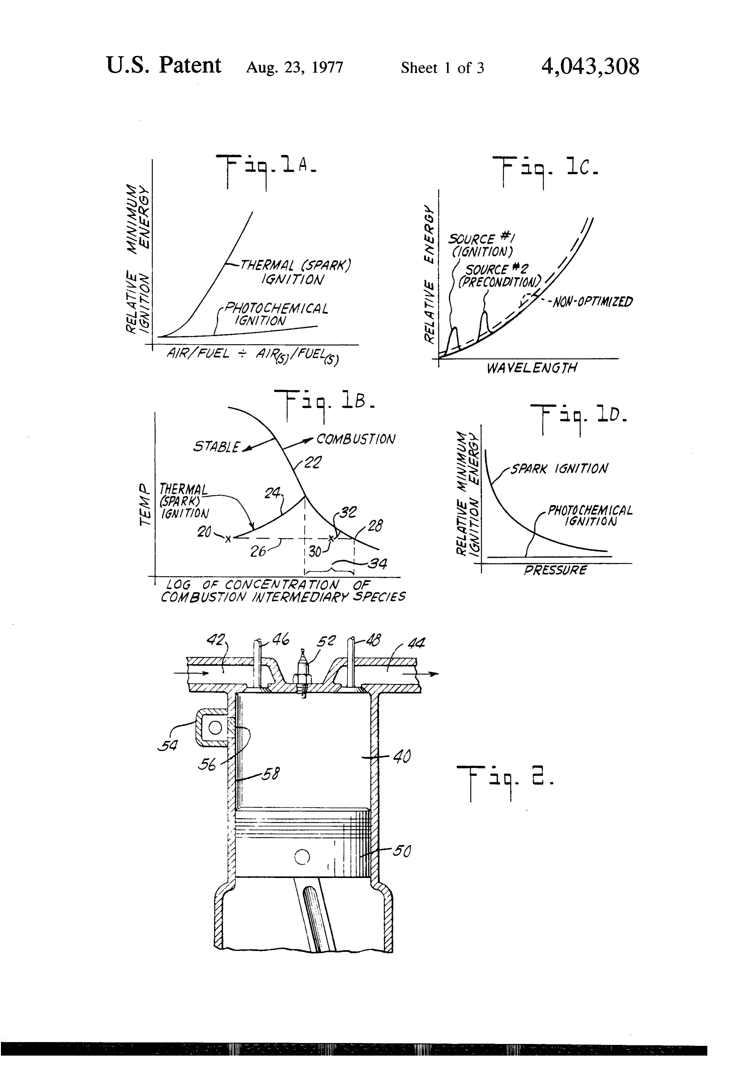
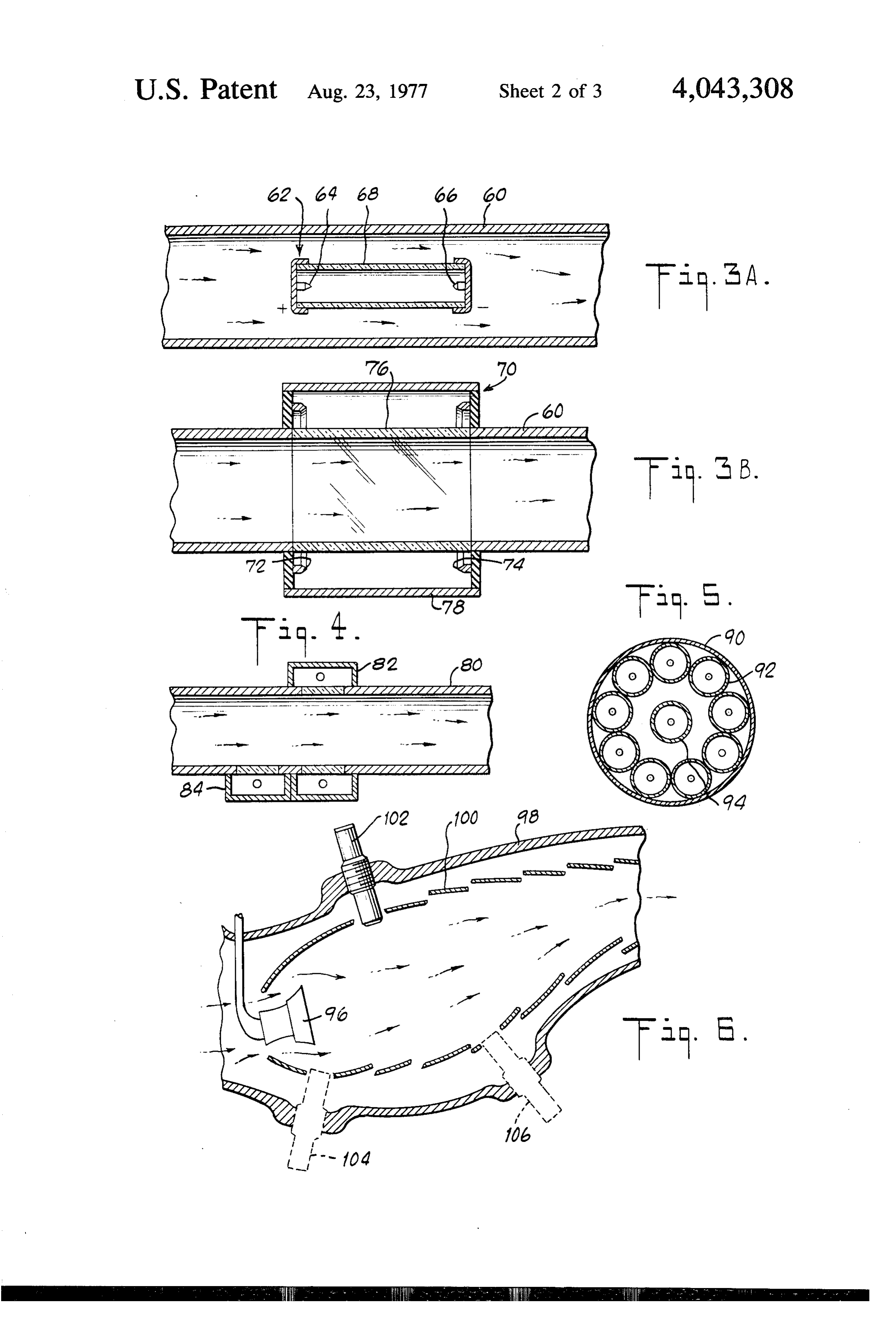
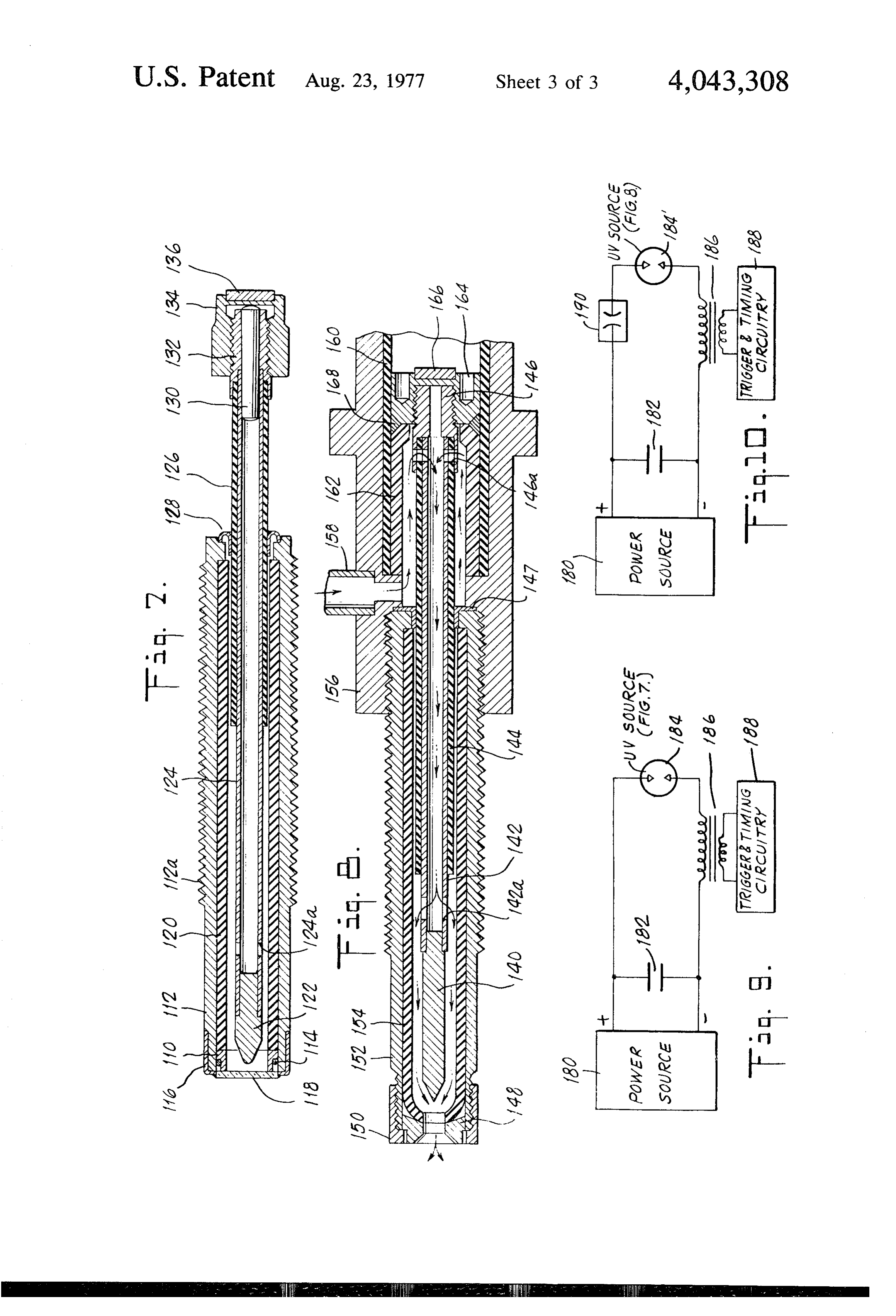
FIGS. 1A, 1B, 1C and 1D are curves useful in under wavelength-regions where strong photon absorption standing the invention. occurs (e.g., absorption cross sections of 50 cm or FIG. 2 is a sectional view of a part of an internal higher). Initiation is possible by utilizing other photodis combustion engine illustrating the invention. 35 sociation wavelength-regions but the process would FIGS. 3A, 3B, 4 and 5 are sectional views of exhaust then require the expenditure of considerably more en systems in accordance with the invention. ergy to offset the "weak' absorption of photons. In the FIG. 6 is a sectional view of a part of a jet engine strong absorption regions the effective penetration of illustrating the invention. radiant energy in air at atmospheric pressure is only in FIGS. 7 and 8 are sectional views of sources for gen the order of 0.02 centimeter. The fact that energy suffi erating ultraviolet radiation. cient for photodissociation is absorbed over such a short FIGS. 9 and 10 are typical circuit diagrams of electri path makes it practical to generate large local concen cal circuits used to energize sources of ultraviolet radia trations of oxygen atoms. (It has been determined that tion. an approximate local concentration of 1014 oxygen 45 atoms per cubic centimeter is sufficient to initiate self
DETAILED DESCRIPTION
sustaining combustion in fuel-oxygen-diluent mixtures
It first will be preferable to consider various aspects of practical interest.) However, radiant energy in these of photochemical ignition, in general. As noted above, strong absorption regions does not have the penetration the present invention is directed to the control of the needed to efficiently affect the combustion process be initiation of self-sustaining combustion as well as the 50 yond in the initiation zone and control the combustion combustion rate and flame propagation velocity in a rate and flame propagation speed at in-depth zones of combustible mixture. This is achieved by irradiating the the mixture.
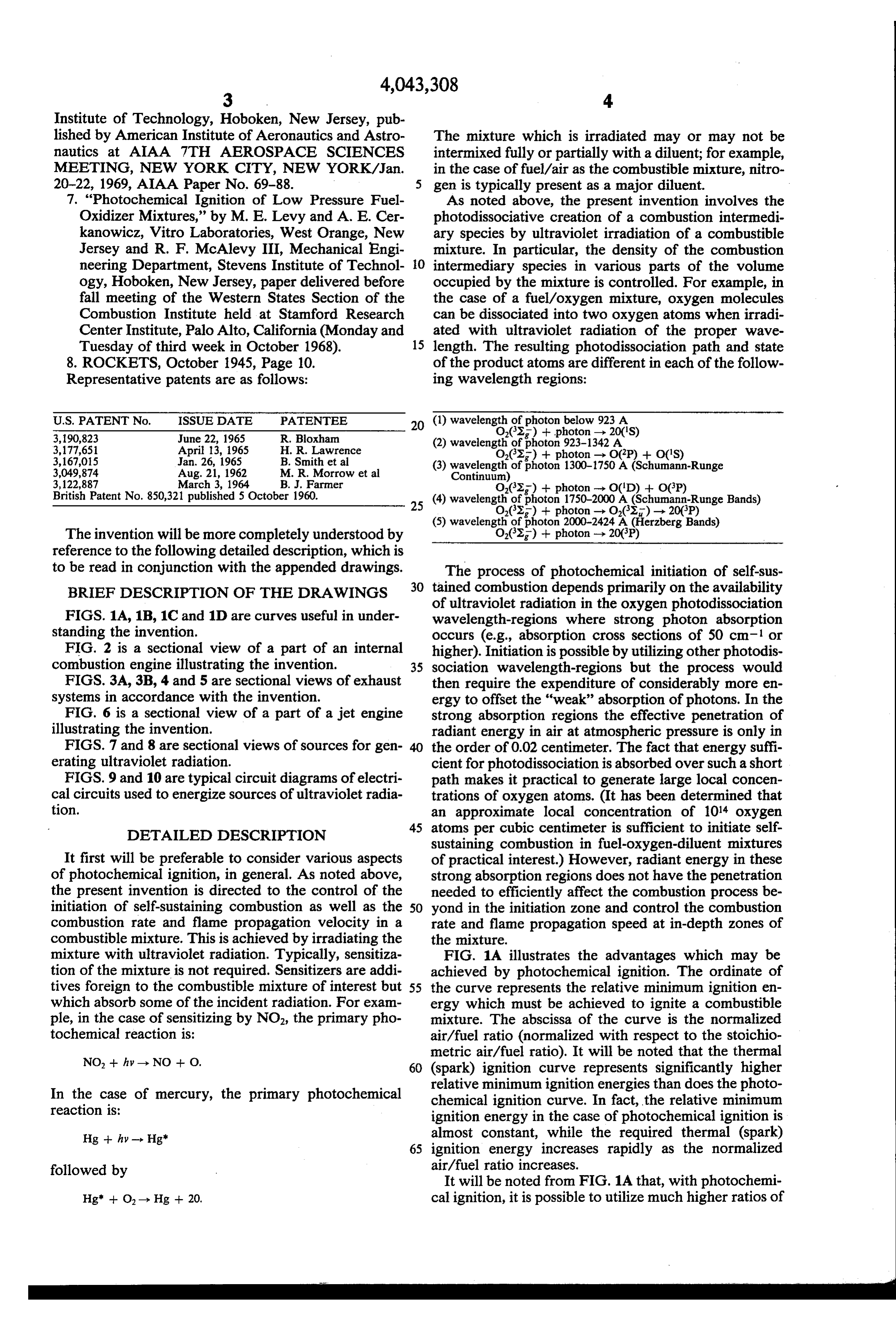
mixture with ultraviolet radiation. Typically, sensitiza FIG. 1A illustrates the advantages which may be tion of the mixture is not required. Sensitizers are addi achieved by photochemical ignition. The ordinate of tives foreign to the combustible mixture of interest but 55 the curve represents the relative minimum ignition en which absorb some of the incident radiation. For exam ergy which must be achieved to ignite a combustible ple, in the case of sensitizing by NO2, the primary pho mixture. The abscissa of the curve is the normalized tochemical reaction is: air/fuel ratio (normalized with respect to the stoichio
metric air/fuel ratio). It will be noted that the thermal 60 (spark) ignition curve represents significantly higher relative minimum ignition energies than does the photo
In the case of mercury, the primary photochemical chemical reaction is: ignition curve. In fact, the relative minimum ignition energy in the case of photochemical ignition is
Hg -- hy-- Hg almost constant, while the required thermal (spark) 65 ignition energy increases rapidly as the normalized followed by air/fuel ratio increases.
It will be noted from FIG. 1A that, with photochemi
Hg" -- O - Hg -- 20, cal ignition, it is possible to utilize much higher ratios of
Page 7
air to fuel than heretofore possible. As is known, the use intersection of the curves 24 and 22) but less than the of fuel-lean combustible mixtures greatly reduces the concentration required for photochemical initiation of generation of pollutants from the combustion process. combustion at the temperature of the mixture (this latter FIG. 1D illustrates the relation between relative mini concentration is represented by the intersection of the mum ignition energy and pressure for normal (spark) 5 curves 26 and 22). It will be appreciated that, if the ignition and photochemically induced ignition and dem radiant ultraviolet energy is only sufficient to produce a onstrates that the latter can be achieved at much lower concentration of combustion intermediary species that pressure than the former without the attendant severe is less than or the equivalent of that which would exist increase in required ignition energy. at the thermal ignition point, then a temperature in FIG. 1B illustrates the combustion enhancement that 10 crease to the thermal ignition temperature will still be is possible through the use of photochemical ignition. required before ignition can occur. Thus, no obvious The curve shown in that figure plots reactant mixture gain is achieved by irradiating the mixture with such a temperature (the ordinate) versus the log of concentra minimal amount of ultraviolet energy. tion of combustion intermediary species (the abscissa). It has been found that the creation of a combustion The point designated 20 represents the normal condi 15 intermediary species (e.g., oxygen atoms) varies tion of a combustible mixture at ambient temperature. throughout a fuel/oxidizer mixture, and for each zone The curve 22 represents, for that mixture, the transition in the mixture is dependent upon the distance of that between a stable (non-ignited) mixture and combustion zone from the source of ultraviole radiation. The con in the mixture. It will be noted that, as the concentration centration of oxygen atoms, for example, is greatest of a combustion intermediary species increases (e.g., the 20 near the source of ultraviolet energy, and decreases as concentration of oxygen atoms in a fuel/oxygen mix the distance from the source increases. Thus, the inten ture increases), the temperature at which combustion sity of penetrating ultraviolet radiation may be selected initiation takes place is reduced. The curve 24 repre to create the desired number of atoms at various loca sents the transition from the point 20 followed during tions within a combustible mixture, for example, to thermal ignition of the mixture. The dashed curve 26, 25 precondition for ignition in various locations and to on the other hand, represents the transition in the mix achieve ignition in others.
ture that is possible through photochemical processes. It has also been found that different wavelength re That is, as the mixture is irradiated with ultraviolet gions are instrumental in creating atomic oxygen spe energy, the concentration of a combustion intermediary cies, for example, at various distances from the source species (for example, oxygen atoms) is increased, with 30 of ultraviolet radiation. Thus, the spectral radiant out out a concomitant temperature change. It is possible, put of one or more radiation sources may be varied to with sufficient irradiation of ultraviolet energy, to achieve desired ignition preconditioning and ignition achieve ignition. In such a case the incident ultraviolet characteristics in a mixture. The attached Table 1 indi radiation must be sufficient to achieve the concentration cates, for a representative mixture, the contribution to represented by point 28 on the curve 22. On the other 35 the creation of oxygen atoms for various zones of differ hand, the incident ultraviolet radiation may be sufficient ent wavelength regions.
only to achieve the point designated 30 in FIG. 1B, for TABLE 1 example. In such a case, ignition is not achieved, but the Fractional Contribution of Indicated Wavelength Region mixture is in a stable condition which is closer to igni in Oxygen Formation for Various Distances from a tion than it was before irradiation. Ignition may be 40 UV Grade Sapphire Window and a 300 Torr achieved from the point 30 in one of two ways. First, wavelength Stoichiometric distance
Hydrogen-Oxygen Mixture from window (cm) further incident ultraviolet radiation may impinge upon region (A) x=0 x=0.01 x=0.30 x=3.0 x=30.0 x=300.0 the combustible mixture so that the mixture follows the 1400-450 0.099 0.0788 -- - -- -- path 26 and achieves the point 28 on the curve 22. Al 1450-500 0.214 0.18 m - - - ternatively, the temperature of the mixture may be 1500-550
raised so that the mixture follows the path designated 32 1600-650 0.140 0.163 0.104 - - - in FIG. 1B. This latter effect may be achieved by a 1650-1700 0.0698 0.0878 0.382 -- - - spark discharge within the mixture, for example. Igni 1750-1800
tion is achieved when the temperature is raised slightly 1800-1850 - - 0.0046 0.099 0.403 0.315 to the value indicated by the intersection of the curves 50 1850-1900
32 and 22. It will be noted that the temperature rise 1950-2000 - - --- --- 0.0082 0.0403
from the point 30 to achieve ignition is much smaller 2000-2050
than the temperature rise along the path 24 from the 2100-250 - - ur-. - 0.00755 0.0373 point 20. 2150-2200 - - -- 0.00737 0.0366
FIG. 1B thus illustrates the enhancement of combus 55 2200-2250
tion that may take place by irradiating a combustible 2300-2350 - - m - 0.00485 0.0242
mixture with ultraviolet energy either to achieve igni 2350-2400
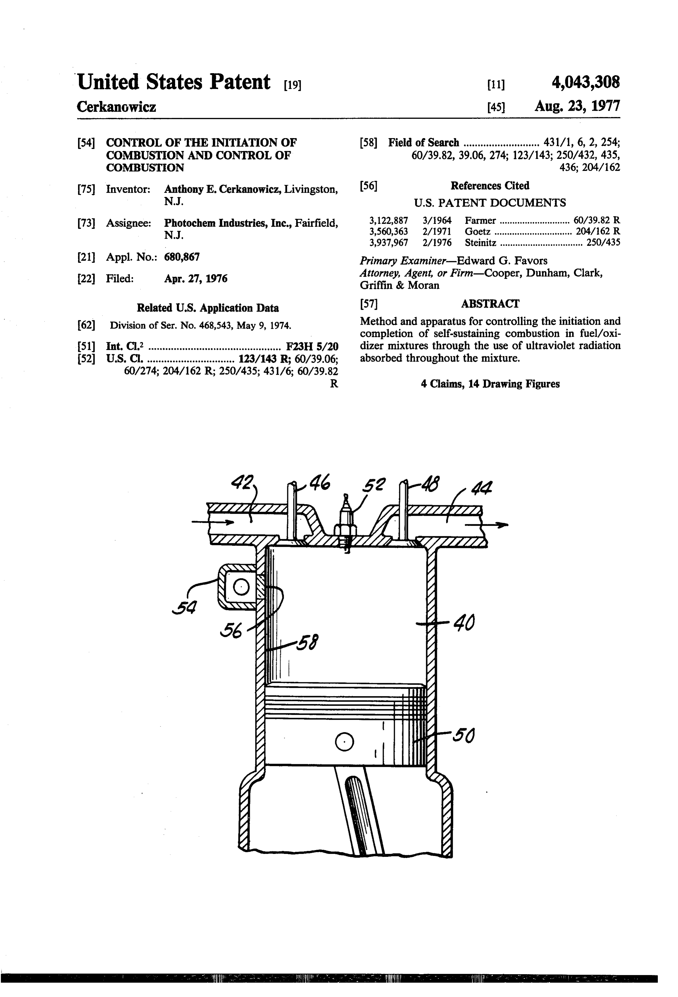
tion by equaling or exceeding the point 28 or enhancing Total 10000 0.9994 0.9973 0.9881 0.99963 1.0001 the ignition process by reaching the point 30, for exam ple. In this regard, it will be noted that, for enhance 60 ment to occur, the incident ultraviolet radiation must be The above principles find application in an automo sufficient to provide a concentration of combustion tive engine, for example, as shown in FIG. 2. A combus intermediary species (oxygen atoms, for example) tible mixture is supplied to combustion chamber 40 via within the range designated 34. This range is repre intake manifold 42. Exhaust gases flow from the com" sented by a concentration of combustion intermediary 65 bustion
Valves chamber 40 through exhaust manifold 44.
46 and 48 control the flow of gases into and out species that is greater than the concentration existing at the thermal ignition temperature of the mixture (the isofone the combustion chamber. The type of engine shown including a reciprocating piston 50, although this thermal ignition temperature is characterized by the
Page 8
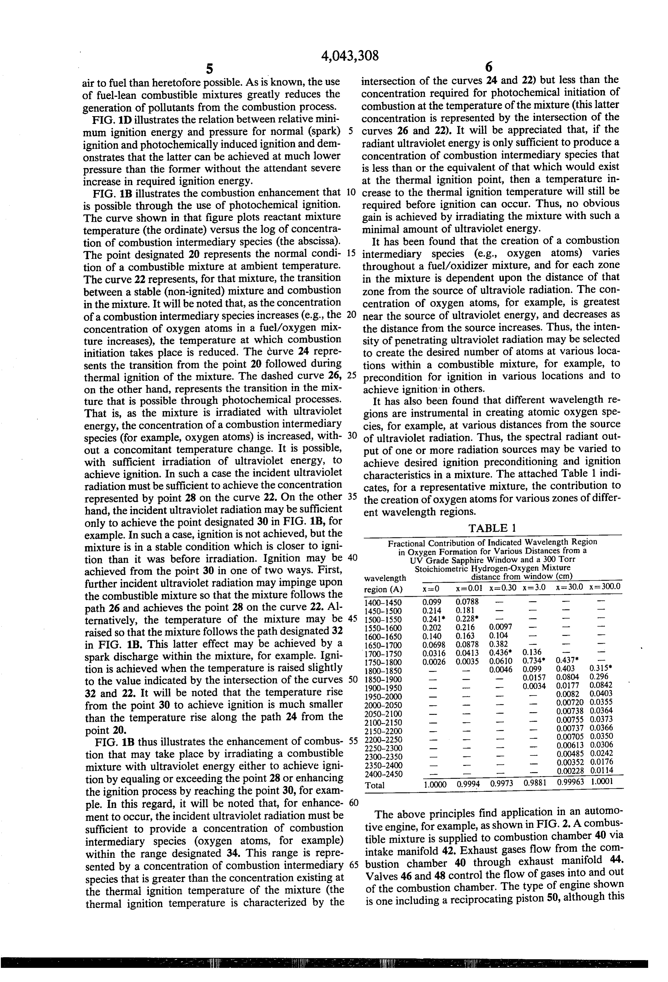
type of engine is chose as being representative only. A The flow of exhaust gas is as shown by the arrows in conventional spark plug 52 is utilized, as well as a FIG. 4, and hence it is apparent that radiation from the source 54 of ultraviolet energy. The source 54 has been source 84 impinges upon and penetrates the exhaust shown only schematically. More detailed examples are gases first, followed by radiation from the source 82. shown in FIGS. 7 and 8, to be described later. The 5 The radiation from the source 84 may, for example, source 54 includes a window 56 which forms a part of precondition the exhaust gases to a point equivalent to the cylinder wall 58 of the combustion chamber. Ultra the point 30 in FIG. 1B. Radiation from the source 82 violet radiation is transmitted through the window 56 may then achieve combustion in the exhaust gas mixture into the combustible mixture within the combustion as by causing the mixture to traverse the path between chamber 40, 10 the points 30 and 28 in FIG. 1B. The sources 82 and 84 In operation, the source 54 of the ultraviolet radiation may also be operated to provide radiation at selected conditions the combustible mixture within the combus wavelengths, which may differ from each other, to be tion chamber 40 typically by providing a concentration described in more detail below, to precondition or con of oxygen atoms corresponding to the point 30 in FIG. dition the exhaust gas mixture at various zones within 1B. At the appropriate time in the cycle of the engine, 15 the mixture, also to be described in more detail below. when the piston 50 is at or near top-dead-center, a spark FIG. 5 shows an exhaust system 90 including a plural is generated in the mixture by the spark plug 52, causing ity of sources 92 spaced along the inside of the system, the mixture to traverse the path 32 in FIG. 1B and thus and a source 94 located along the central axis of the to experience ignition and combustion of the entire system. The sources 92 and 94 may take the form of the mixture. 20 source 62 shown in FIG. 3A, for example. In any event, The spark plug 52 could be replaced by another the sources 92 and 94 irradiate the exhaust mixture with source of ultraviolet radiation similar to the source 54, ultraviolet energy conditioning that mixture so as to in which case ignition could be achieved by photo provide for combustion therein, thereby reducing and chemical means entirely. In other words, operation removing pollutants.
along the curve 26 of FIG. 1B to the point 30 could be 25 FIG. 6 illustrates the application of photochemical achieved by the ultraviolet source 54, and operation ignition to a jet engine (typically an aircraft engine). along the same curve from the point 30 to the point 28 Fuel is supplied by a fuel spray nozzle 96. Primary air is could be achieved by the second ultraviolet source supplied which flows as shown by the arrows about the replacing the spark plug 52. A single ultraviolet source nozzle 96. Secondary and cooling air flows between (as the source 54) could be employed to achieve igni 30 outer wall 98 of the combustion chamber and inner liner tion. In any event, operation of such an engine at air/f- 100. A source 102 of ultraviolet radiation is positioned uel ratios greater than 19 and exhaust gas recycling back within the wall 98 and extends into the combustion into the combustion process of from 0 to 13% is achiev chamber through the liner 100. The source 102 may able, resulting in fuel savings and substantial reductions take the form, for example, of the sources shown in of NO emissions. 35 FIGS. 7 and 8 to be described below. A plurality of Application of the above principles to exhaust sys such sources may be utilized as shown by assemblies 104 tems is shown in FIGS. 3A and 3B. In FIG. 3A, exhaust and 106 drawn in dashed line. One or more of the system 60 includes a source 62 of ultraviolet radiation sources 102,104 and 106 may be utilized to precondition positioned therein so that the exhaust gases flow there the combustible mixture as well as to ignite and com about. The source 62 may typically comprise electrodes 40 plete combustion therein. The sources may provide 64 and 66 spaced from each other and positioned within radiation of varying intensities at varying wavelengths a cylindrical envelope 68 which may be of sapphire or penetrating selected zones within the mixture to en other similar ultraviolet radiation transmitting material hance the combustion process, and may be timed to and which is filled typically with an inert gas. A steady operate together or sequentially, for example. state or pulsed electrical discharge between the elec 45 FIG. 7 shows a representative source of ultraviolet trodes 64 and 66 results in the generation of ultraviolet radiation. The source is comprised of an annular elec energy which is transmitted through the evelope 68 into trode 110 which may be made of tungsten, for example. the gaseous exhaust medium surrounding the source 62. The electrode is press fitted into a tubular body 112 Further completion of combustion in the exhaust gas which may be of steel or kovar, for example. Kovar is medium is thus possible by the generation of combus 50 comprised generally of 29% nickel, 17% cobalt, and tion intemediary species created by the ultraviolet radi 54% iron. A ring 114 (e.g., copper) may be employed to ation. secure the press fitting of the electrode 110 to the body In FIG. 3B, exhaust system 60 includes a source 70 in 112 and to provide for good electrical conduction there the form of annular electrodes 72 and 74 which encircle between. A cup 116 (e.g., kovar) is secured by braising the exhaust system. In this case the wall structure of the 55 or a similar procedure to the body 112. A window 118 exhaust system includes a cylindrical window 76 of is secured by braising or similar securing technique to ultraviolet radiation-transmitting material to transmit the cup 116. The window 118 may be of sapphire, for the radiation from the electrodes 72 and 74 into the example, or other suitable material for the transmission exhaust medium. Outer envelope 78 may be of any of ultraviolet energy. The outer portion of the body 112 suitable material, which may be opaque or transparent 60 may be threaded, as at 112a to secure the entire assem to ultraviolet radiation. bly into a wall structure in use. For example, the FIG. 4 shows an alternative arrangement in an ex threaded portion 112a may be utilized to secure the haust system 80. Source 82 has been shown schemati source 102 within the wall structure 98 of the jet engine cally, and may be the same as source 70 in FIG. 3B, for shown in FIG. 6 and described above. example. Source 84 is also shown schematically and 65 The source shown in FIG. 7 includes an insulating may be the same as source 70 shown in FIG. 3B or may, liner 120 which may be of alumina or other similar for example, take the form of one of the sources shown insulating material. A central electrode 122 (e.g., tung in FIGS. 7 and 8 to be described in more detail below. sten) is included which is rod-shaped, the tip portion of
Page 9
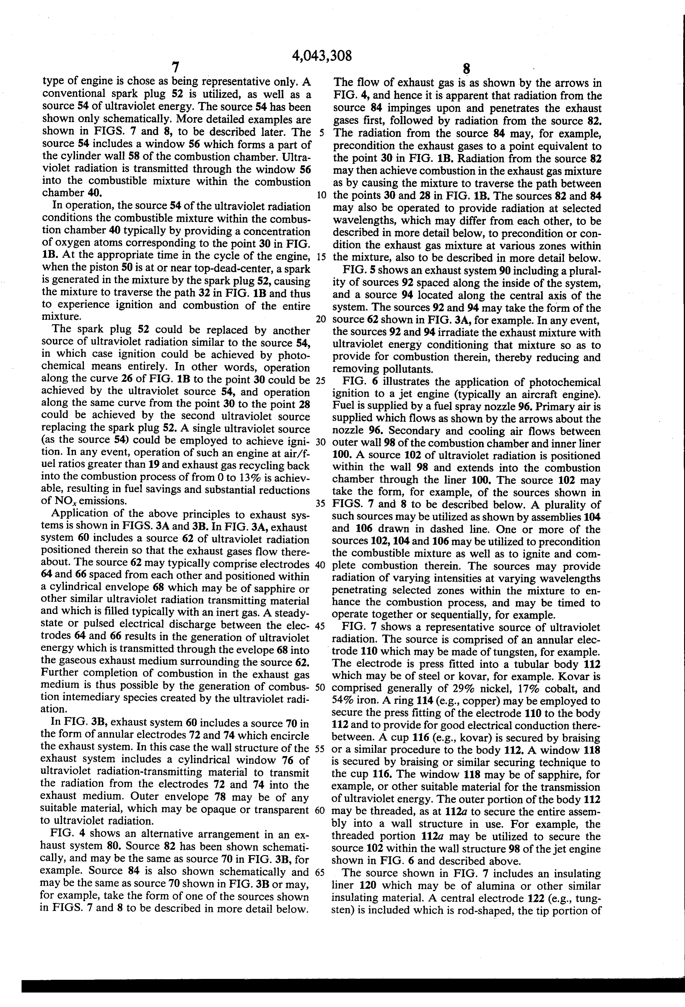
which is positioned inside of and coaxially with the such wavelengths of energy. The source is similar in annular electrode 110. A cylindrical conductive mem features and materials to that shown in FIG. 7, except ber 124, which may be of molybdenum, for example, is that it completely lacks a window. The source includes secured to the central electrode 122. An insulating a central electrode 140 attached to tubular member 142 sleeve 126 (e.g., alumina) surrounds the rear portion of 5 which extends rearwardly (to the right). The tube 142, the conductive tube 124. A sealing piece 128 (e.g., ko which is conductive, is surrounded by a non-conductive var) seals the insulating sleeve 126 to the body member sleeve 144. The sleeve 144 and tube 142 terminate in a 112. At the right-hand end of the assembly, the conduc threaded member 146 which includes gas ports 146a tive tube 124 has press fitted thereto a tapered pin 130 therein. A retaining piece 147 (e.g., kovar) is attached to (e.g., stainless steel, copper and lead coated). A 10 the insulating member 144. An annular electrode 148 is threaded connector 132 (e.g., kovar) is secured (by included at the left-hand end of the assembly and held braising, for example) to the insulating sleeve 126 and by a threaded cap 150 which is threaded onto threaded the conductive tube 124. An end cap 134 (e.g., brass) is end portion of body member 152. It will be noted that threaded onto the connector 132 and includes an end the contral electrode 140 is coaxial with the annular button 136 (e.g., tungsten brazed to cap 134) which 15 electrode; however, the tip portion of the central elec makes electrical contact with the threaded connector 132 through cap 134. Electrical contact is thus estab trode is not within the annular electrode but is spaced to lished with the central electrode 122 by way of the is secured(totothetheright) the rear thereof. An insulating sleeve 154 inside of the body member 152. The conductive button 136 and with the annular electrode 110 via the body member 112. 20 right-hand end of the body member 152 is threaded and
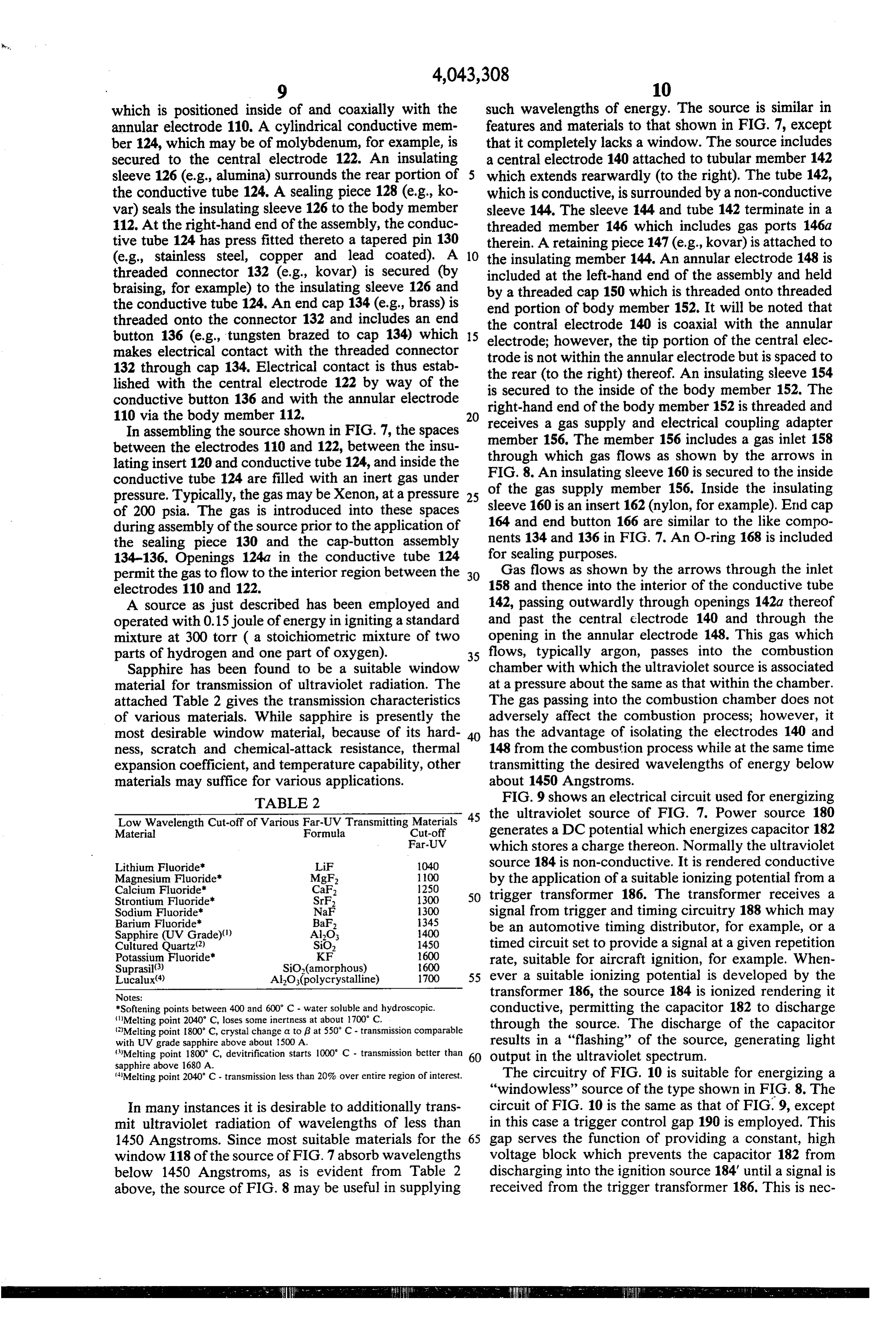
In assembling the source shown in FIG. 7, the spaces receives member a gas supply and electrical coupling adapter 156. The member 156 includes a gas inlet 158 between the electrodes 110 and 122, between the insu through which gas flows as shown by the arrows in lating insert 120 and conductive tube 124, and inside the FIG. 8. An insulating sleeve 160 is secured to the inside conductive tube 124 are filled with an inert gas under of the gas supply member 156. Inside the insulating pressure. Typically, the gas may be Xenon, at a pressure 25 of 200 psia. The gas is introduced into these spaces sleeve 160 is an insert 162 (nylon, for example). End cap during assembly of the source prior to the application of 164 and end button 166 are similar to the like compo the sealing piece 130 and the cap-button assembly nents 134 and 136 in FIG. 7. An O-ring 168 is included 134-136. Openings 124a in the conductive tube 124 for sealing purposes.
permit the gas to flow to the interior region between the 30 Gas flows as shown by the arrows through the inlet electrodes 110 and 122. 158 and thence into the interior of the conductive tube A source as just described has been employed and 142, passing outwardly through openings 142a thereof operated with 0.15 joule of energy in igniting a standard and past the central electrode 140 and through the mixture at 300 torr ( a stoichiometric mixture of two opening in the annular electrode 148. This gas which parts of hydrogen and one part of oxygen). 35 flows, typically argon, passes into the combustion Sapphire has been found to be a suitable window chamber with which the ultraviolet source is associated material for transmission of ultraviolet radiation. The at a pressure about the same as that within the chamber. attached Table 2 gives the transmission characteristics The gas passing into the combustion chamber does not of various materials. While sapphire is presently the adversely affect the combustion process; however, it most desirable window material, because of its hard 40 has the advantage of isolating the electrodes 140 and ness, scratch and chemical-attack resistance, thermal 148 from the combustion process while at the same time expansion coefficient, and temperature capability, other transmitting the desired wavelengths of energy below materials may suffice for various applications. about 1450 Angstroms.
TABLE 2 FIG. 9 shows an electrical circuit used for energizing 45 the ultraviolet source of FIG. 7. Power source 180
Low Wavelength Cut-off of Various Far-UV Transmitting Materials generates a DC potential which energizes capacitor 182 Material Formula Cut-off
Far-UV which stores a charge thereon. Normally the ultraviolet
Lithium Fluoride LiF 1040 source 184 is non-conductive. It is rendered conductive Magnesium Fluoride"
Calcium Fluoride"
MgF,
CaF
by the application of a suitable ionizing potential from a
Strontium Fluoride SrF, 1300 50 trigger transformer 186. The transformer receives a Sodium Fluoride NaF 1300 signal from trigger and timing circuitry 188 which may Barium Fluoride BaF, 1345 be an automotive timing distributor, for example, or a Sapphire (UV Grade).() AlOs 400
Cultured Quartz(2) SiO, 1450 timed circuit set to provide a signal at a given repetition Potassium Fluoride"
Suprasil()
600 rate, suitable for aircraft ignition, for example. When
Lucalux() AlO3(polycrystalline) 1700 55 ever a suitable ionizing potential is developed by the Notes: transformer 186, the source 184 is ionized rendering it *Softening points between 400 and 600 C - water soluble and hydroscopic.
Melting point 2040 C, loses some inertness at about 700 C.
conductive, permitting the capacitor 182 to discharge
Melting point i800 C, crystal change a top at 550° C - transmission comparable through the source. The discharge of the capacitor with UV grade sapphire above about 1500 A. results in a "flashing' of the source, generating light Melting point 1800 C, devitrification starts 1000 C - transmission better than 60 output in the ultraviolet spectrum. sapphire above 1680 A.
Melting point 2040 C - transmission less than 20% over entire region of interest. The circuitry of FIG. 10 is suitable for energizing a "windowless” source of the type shown in FIG.8. The
In many instances it is desirable to additionally trans circuit of FIG. 10 is the same as that of FIG.9, except mit ultraviolet radiation of wavelengths of less than in this case a trigger control gap 190 is employed. This 1450 Angstroms. Since most suitable materials for the 65 gap serves the function of providing a constant, high window 118 of the source of FIG. 7 absorb wavelengths voltage block which prevents the capacitor 182 from below 1450 Angstroms, as is evident from Table 2 discharging into the ignition source 184 until a signal is above, the source of FIG.8 may be useful in supplying received from the trigger transformer 186. This is nec
Page 10
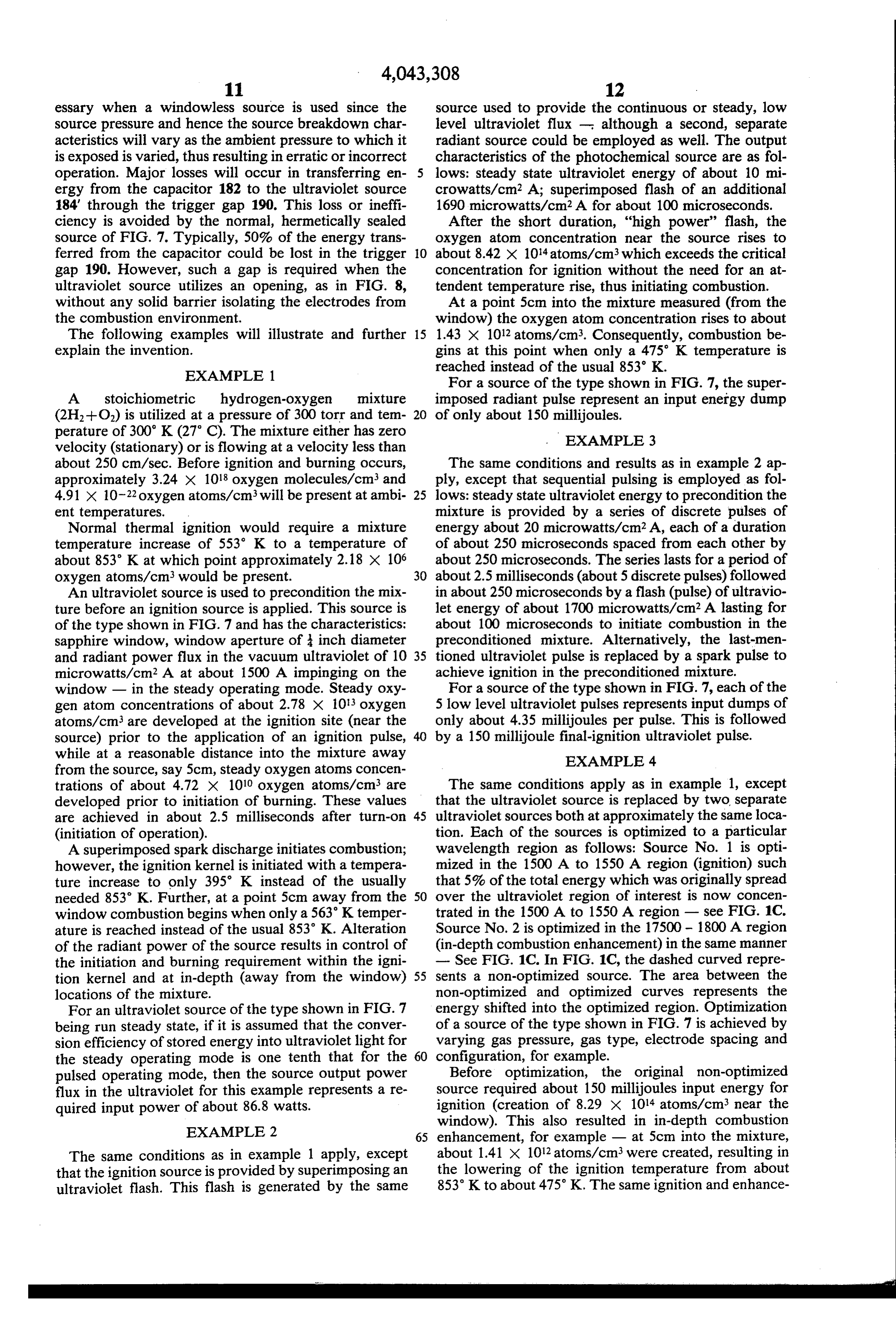
essary when a windowless source is used since the source used to provide the continuous or steady, low source pressure and hence the source breakdown char level ultraviolet flux - although a second, separate acteristics will vary as the ambient pressure to which it radiant source could be employed as well. The output is exposed is varied, thus resulting in erratic or incorrect characteristics of the photochemical source are as fol operation. Major losses will occur in transferring en lows: steady state ultraviolet energy of about 10 mi ergy from the capacitor 182 to the ultraviolet source crowatts/cm2 A; superimposed flash of an additional 184 through the trigger gap 190. This loss or ineffi 1690 microwatts/cm2A for about 100 microseconds. ciency is avoided by the normal, hermetically sealed After the short duration, “high power' flash, the source of FIG. 7. Typically, 50% of the energy trans oxygen atom concentration near the source rises to ferred from the capacitor could be lost in the trigger O about 8.42 X 10¹⁴ atoms/cm3 which exceeds the critical gap 190. However, such a gap is required when the concentration for ignition without the need for an at ultraviolet source utilizes an opening, as in FIG. 8, tendent temperature rise, thus initiating combustion. without any solid barrier isolating the electrodes from At a point 5cm into the mixture measured (from the the combustion environment. window) the oxygen atom concentration rises to about The following examples will illustrate and further 15 1.43 x 10¹² atoms/cm3. Consequently, combustion be explain the invention. gins at this point when only a 475 K temperature is reached instead of the usual 853 K.
EXAMPLE 1.
For a source of the type shown in FIG. 7, the super
A stoichiometric hydrogen-oxygen mixture imposed radiant pulse represent an input energy dump (2H2--O.) is utilized at a pressure of 300 torr and tem of only about 150 millijoules. perature of 300 K (27° C). The mixture either has zero EXAMPLE 3 velocity (stationary) or is flowing at a velocity less than about 250 cm/sec. Before ignition and burning occurs, The same conditions and results as in example 2 ap approximately 3.24 x 10¹⁸ oxygen molecules/cm3 and ply, except that sequential pulsing is employed as foll 4.91 X 10⁻²² oxygen atoms/cm3 will be present at ambi 25 lows: steady state ultraviolet energy to precondition the ent temperatures. mixture is provided by a series of discrete pulses of Normal thermal ignition would require a mixture energy about 20 microwatts/cm2A, each of a duration temperature increase of 553 K to a temperature of of about 250 microseconds spaced from each other by about 853 K at which point approximately 2.18 x 10⁶ about 250 microseconds. The series lasts for a period of oxygen atoms/cm3 would be present. 30 about 2.5 milliseconds (about 5 discrete pulses) followed An ultraviolet source is used to precondition the mix in about 250 microseconds by a flash (pulse) of ultravio ture before an ignition source is applied. This source is let energy of about 1700 microwatts/cm2 A lasting for of the type shown in FIG. 7 and has the characteristics: about 100 microseconds to initiate combustion in the sapphire window, window aperture of inch diameter preconditioned mixture. Alternatively, the last-men and radiant power flux in the vacuum ultraviolet of 10 35 tioned ultraviolet pulse is replaced by a spark pulse to microwatts/cm2 A at about 1500 A impinging on the achieve ignition in the preconditioned mixture. window - in the steady operating mode. Steady oxy For a source of the type shown in FIG. 7, each of the gen atom concentrations of about 2.78 x 10³ oxygen 5 low level ultraviolet pulses represents input dumps of atoms/cm3 are developed at the ignition site (near the only about 4.35 millijoules per pulse. This is followed source) prior to the application of an ignition pulse, by a 150 millijoule final-ignition ultraviolet pulse. while at a reasonable distance into the mixture away EXAMPLE 4 from the source, say 5cm, steady oxygen atoms concen trations of about 4.72 X 10¹⁰ oxygen atoms/cm are The same conditions apply as in example 1, except developed prior to initiation of burning. These values that the ultraviolet source is replaced by two separate are achieved in about 2.5 milliseconds after turn-on 45 ultraviolet sources both at approximately the same loca (initiation of operation). tion. Each of the sources is optimized to a particular A superimposed spark discharge initiates combustion; wavelength region as follows: Source No. 1 is opti however, the ignition kernel is initiated with a tempera mized in the 1500 A to 1550 A region (ignition) such ture increase to only 395 K instead of the usually that 5% of the total energy which was originally spread needed 853 K. Further, at a point 5cm away from the 50 over the ultraviolet region of interest is now concen window combustion begins when only a 563 K temper trated in the 1500A to 1550 A region - see FIG. 1C. ature is reached instead of the usual 853 K. Alteration Source No. 2 is optimized in the 17500 - 1800 A region of the radiant power of the source results in control of (in-depth combustion enhancement) in the same manner the initiation and burning requirement within the igni - See FIG. 1C.. In FIG. 1C, the dashed curved repre tion kernel and at in-depth (away from the window) 55 sents a non-optimized source. The area between the locations of the mixture. non-optimized and optimized curves represents the For an ultraviolet source of the type shown in FIG. 7 energy shifted into the optimized region. Optimization being run steady state, if it is assumed that the conver of a source of the type shown in FIG. 7 is achieved by sion efficiency of stored energy into ultraviolet light for varying gas pressure, gas type, electrode spacing and the steady operating mode is one tenth that for the 60 configuration, for example.
pulsed operating mode, then the source output power Before optimization, the original non-optimized flux in the ultraviolet for this example represents a re source required about 150 millijoules input energy for quired input power of about 86.8 watts. ignition (creation of 8.29 x 10¹⁴ atoms/cm3 near the
EXAMPLE 2
window). This also resulted in in-depth combustion 65 enhancement, for example - at 5cm into the mixture,
The same conditions as in example 1 apply, except about 1.41 x 10¹² atoms/cm3 were created, resulting in that the ignition source is provided by superimposing an the lowering of the ignition temperature from about ultraviolet flash. This flash is generated by the same 853 K to about 475 K. The same ignition and enhance
Page 11
ment effects are achieved by pulsing both of the opti result, these weaker ultraviolet radiation absorption mized sources instead of a single non-optimized source. regions may be used to control the combustion rate and Identical effects are obtained by pulsing source No. 1 at flame propagation speed by dissociating a number of 38 millijoules and source No. 2 at 33 millijoules. Thus oxygen molecules within a fuel-oxygen-diluent mixture, the total pulse energy required is reduced from 150 5 thus creating oxygen atoms that are present when the millijoules to about 71 millijoules. combustion process engulfs an in-depth volume of the If only optimized source No. 1 were used, ignition reactant mixture. The number of oxygen atoms created would be achieved with the expenditure of only about in this manner prior to the arrival of a flame front can be 48 millijoules (instead of 71 millijoules noted above). sufficient for controlling the rate of combustion and However, the enhancement effect would be reduced, 10 flame front propagation speed, but not necessarily suffi with only about 4.28 x 10¹¹ oxygen atoms/cm3 being cient to produce initiation of combustion throughout created at a depth of 5cm. This results in lowering the the volume of the fuel-oxygen-diluent mixture. ignition temperature from 853 K (without enhance An ultraviolet radiation source (or sources) is used to ment) to about 515 K. Thus the equivalent of 40 K. provide ultraviolet radiation in regions desired. Radia enhancement effect is lost compared to the above exam 15 tion in various regions of interest can be generated si ple but a savings in input energy of about 32% is real multaneously or timed at intervals. The weak penetra ized. tion-strong absorption regions are primarily used in initiating the self-sustaining combustion process. The
EXAMPLE 5 strong pentration-weak absorption regions are primar The same conditions as in example 1 apply, except 20 ily used in controlling combustion processes. It is clear that combustion is initiated at one end of a tubular that by controlling the intensity in the photochemical chamber 5cm in diameter and also the combustion pro enhancement regions as well as the timing of irradiation cess is affected at a distance 5cm away from the ignition relative to the initiation of combustion, photochemical site on the center line of the chamber. These require initiation and control of initiation of the combustion ments are met by using two sources: Source No. 1 is 25 process, as well as control of the combustion rate and located near the ignition site on the axis of the tubular flame propagation speed, can be obtained. chamber, and is optimized in the 1500 - 1550 A region Although the primary mechanism for initiation and for ignition as per the previous example. Source No. 2 is control of combustion is the photodissociation of oxy located 5cm away from the ignition site in the side wall gen molecules into two oxygen atoms, it should be of the chamber. This locates it 2.5cm away from the 30 noted that during the irradiation process other species desired enhancement area. Source No. 2 is optimized in may be formed within the same volume of the fuel-oxy the 1750 - 1800 A region as per the previous example. gen-diluent mixture. Such species could be excited oxy Ignition is achieved by pulsing source No. 1 at a 48 gen molecules, excited molecules and atoms of the fuel millijoule input level (assuming typical efficiencies of or the dileunt, or the intermediary species produced by the source of the type shown in FIG. 7). When the 35 the ensuing reactions. The presence of each species constitutes the creation of a combustion intermediary in-depth enhancement goal at the 5cm distance is a reduction of ignition temperature from the normal 853 species.
K to 475 K, source No. 2 is supplied at a pulse energy The techniques described in the present application level of only about 9.5 millijoules. Thus the total energy may be used to eliminate or reduce some or all of the consumed is only about 57.5 millijoules compared with various limitations inherent in other combustion initia 71.0 millijoules if both sources were at the ingition site tion processes mentioned above (e.g., spark), as well as as in example 4. to provide for the control of the rate of combustion and the speed of the propagation of the flame that is gener
EXAMPLE 6 ated. Photochemical initiation of combustion, control of The same conditions as in example 2 apply, except 45 initiation of combustion and control of combustion by that two sources are used. One source provides a steady can means of irradiation by selected ultraviolet radiation or quasi-steady (duration times of about 2 to 3 millisec be used effectively over a wide range of pressure, onds) radiant flux of about 10 microwatts/cm2 A. The temperature, flow conditions, turbulence, fuel type and Second source is sequenced to pulse after time periods stoichiometry. Furthermore, the techniques can be used equal to or greater than 2 to 3 milliseconds and provides 50 to reduce the delays in the combustion initiation process about 1700 microwatts/cm2A. and enhance mixing fuel-oxygen-diluent reactant mix Each source may be tuned for a particular wave tures and control combustion instabilities. It will be evident that many different techniques as length distribution.
outlined above are possible. For example, a continuous,
SUMMARY 55 pulsed or modulated power supply may be utilized,
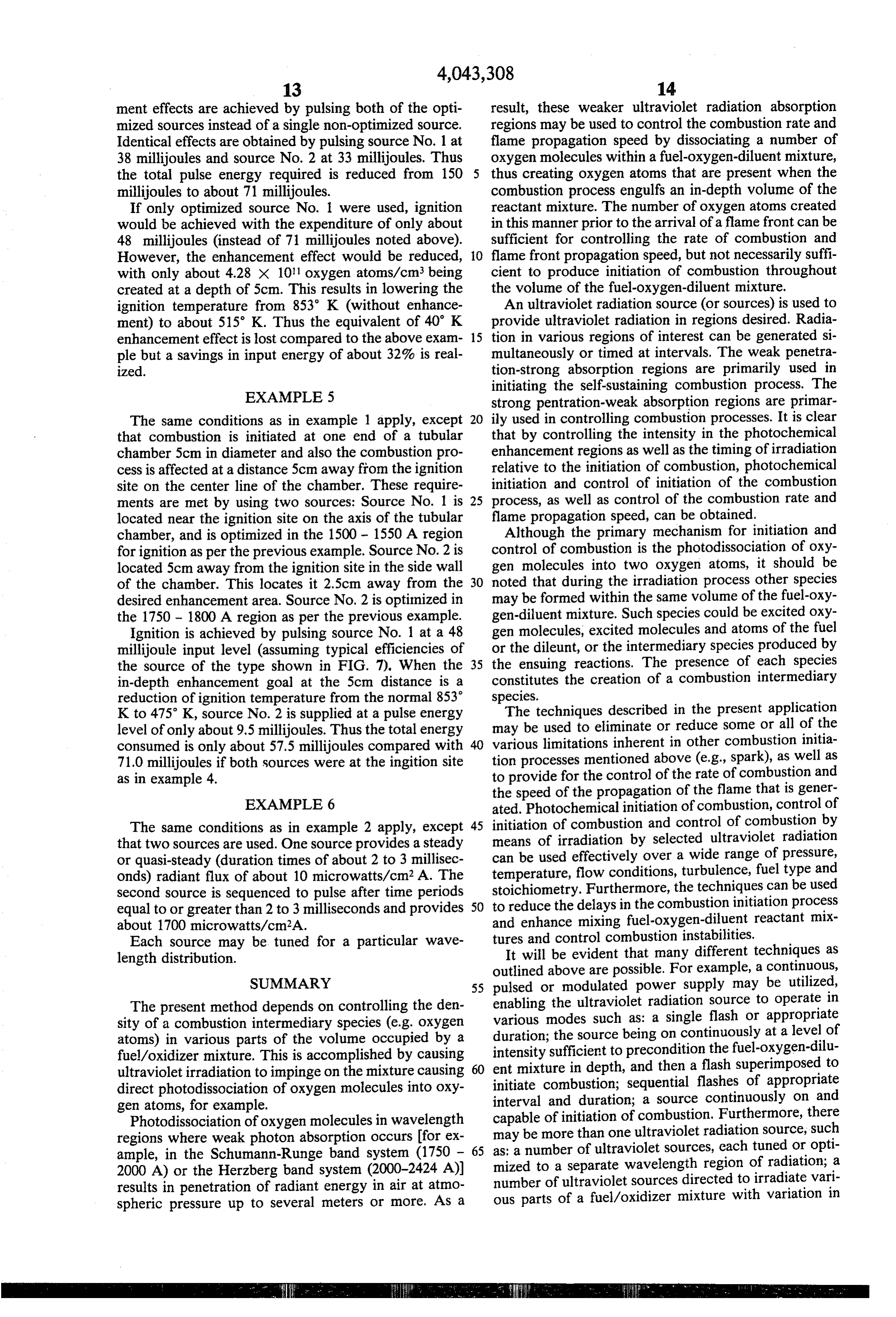
The present method depends on controlling the den enabling the ultraviolet radiation source to operate in sity of a combustion intermediary species (e.g. oxygen various modes such as: a single flash or appropriate atoms) in various parts of the volume occupied by a duration;sufficient the source being on continuously at a level of fuel/oxidizer mixture. This is accomplished by causing intensity to precondition the fuel-oxygen-dilu ent mixture in depth, and then a flash superimposed to ultraviolet irradiation to impinge on the mixture causing 60 initiate combustion; sequential flashes of appropriate direct photodissociation of oxygen molecules into oxy gen atoms, for example. interval and duration; a source continuously on and Photodissociation of oxygen molecules in wavelength capable of initiation of combustion. Furthermore, there regions where weak photon absorption occurs for ex may be more than one ultraviolet radiation source, such ample, in the Schumann-Runge band system (1750 - 65 as: a number of ultraviolet sources, each tuned or opti 2000 A) or the Herzberg band system (2000-2424 A)) mized number to a separate wavelength region of radiation; a of ultraviolet sources directed to irradiate vari results in penetration of radiant energy in air at atmo spheric pressure up to several meters or more. As a ous parts of a fuel/oxidizer mixture with variation in
Page 12
spectral distribution and intensity of the radiant output; by providing for reliable and positive ignition and com a number of ultraviolet sources used in sequence or bustion of the appropriate fuel-lean mixtures, with or phased according to a preselected timing sequence that without exhaust gas recycle. However, ignition of fuel provides varying intensities and spectral distributions of air mixtures by means of spark sources becomes increas ultraviolet radiation to the reactant mixture at varying ingly difficult and eventually impossible when the reac times. tant mixture is made progressively more fuel-lean. Pho There may also be varied geometric relationship be tochemical ignition and combustion control of reactant tween a radiation source and a combustion chamber, mixtures does not experience the same difficulties. such as one source to one chamber, one source for many A comparison between the two methods, shown in chambers, one chamber with many sources. 10 FIG. 1A, illustrates the vastly different characteristics An important realization of the present invention is that can be obtained by using the photochemical tech that increasing the input energy results in a pronounced nique. Energy requirements for spark ignition of fuel effect on the reaction front propagation velocity. For lean mixtures increase drastically compared to energy example, a stoichiometric hydrogen-oxygen mixture at requirements for photochemical ignition as the mixture 300 torr pressure and room temperature was exposed to 15 is made leaner.
radiant energy levels which resulted from 200 to 300 The increased ignition capability may be used to su joule energy inputs. The reaction front arrival time at cessfully operate internal combustion engines at condi photo-cells positioned at 7.52 cm and 12.52 cm from the tions which currently represent regions of poor com radiant source window (ultraviolet grade sapphire) was bustion. This would then provide for operation at interpreted to demonstrate that an increase in input 20 greatly reduced NO levels, either with or without ex energy by a factor of 10 results in reducing the reaction haust gas recycle. .
front arrival time approximately 500%. It is expected In operation, the spark plug and its associated elec that a similar reduction in ignition delay can be brought tronics is replaced by a photochemical ignition source about by increasing the input energy. The proposal that with its electronics, or if not replaced then accompanied enhancement in depth is created by the generation of 25 by a photochemical ignition source. The engine is oxygen atoms is thus supported since, in the region turned to run fuel-lean with or without exhaust gas discussed, ten times the normal oxygen atom concentra recycle.
tion is generated for ten times the amount of energy. A second aspect of pollution control within the com Increasing the input energy results in an increase in bustion chamber is based on the finding that nitric oxide reaction front propagation velocity. 30 is formed in significant concentrations only in the post It should be noted that there are no presently known flame reactions following passage of a flame front. That window materials that transmit photons below 1000 A is, it forms at an insignificant rate at temperatures en (lithium fluoride windows transmit radiation down to countered through the flame front, and only begins to about 1040 A). As a result, if radiation below the LiF proceed at a rapid rate at the high temperatures charac ultraviolet cut-off wavelength is desired, the operation 35 teristic of the combustion products. Thus, it is possible of an ultraviolet source has to be windowless by neces to describe the formation time of nitric oxide at the sity. Operation in this mode is as discussed in connec combustion products temperature by a characteristic tion with FIG. 8, and provides lower wavelength radia time, Tno.
tion than that normally available from sealed radiant Since to is determined by gas-phase chemical kinet Sources. This results in additional contributions to the 40 ics, and thus is a strong function of combustion product important oxygen photodissociative reactions, above temperature (as is the equilibrium nitric oxide concen the normally possible when sources with windows are tration), it is susceptible to control through variation of used. Further, windowless operation avoids the poten fuel-air ratio (as is the equilibrium nitric oxide concen tial problem of window transmission loss due to con tration). For example, changing the fuel-air ratio from a tamination, either internal or external. In terms of prac 45 fuel-rich to a fuel-lean condition (say equivalent ratio tical industrial materials available, sapphire (which 1.2 to 0.9) results in an increase in r from a few msec transmits radiant energy down to about 1430 A) and to approximately 10 msec in gasoline-fueled automotive special quartz (which transmits radiant energy down to engines.
about 1550 A) provide the lowest usable wavelengths. An important aspect of the photochemical control Sapphire is preferable to quartz because of its lower 50 technique is that ignition and flame propagation are ultraviolet cut-off limit. Lower wavelength transmit affected using the photochemical ignition process as ting windows (such as lithium fluoride) do not have the opposed to spark ignition. For example, photochemical necessary structural strength, have high temperature ignition of a methane-air mixture can be made to occur limitations, and are hydroscopic; all of these features at room temperature in times much less than the time being undesirable in most practical situations. 55 involved in spark ignition and the ensuing propagating An important aspect of the present invention relates reaction front is stronger even without motion in the to the use of photochemical ignition and combustion unburned gas. On the other hand, electric spark (ther control within the combustion chamber of an internal mal) ignition requires first a large temperature rise combustion device for the purpose of reducing or elimi above room temperature, and propagates a weaker re nating engine exhaust pollutants, particularly nitric 60 action front for similar conditions. oxides. Pollution control is achieved by taking advan In practice, substitution of a photochemical ignition tage of the different combustion characteristics that are source for a spark-ignition source should reduce the possible with the photochemical method compared to time required for combustion of the fuel charge. This the spark method. Direct control within the combustion permits retardation of ignition until the piston is close to chamber is accomplished by either initiating a rapid 65 top dead center or to the power stroke. Fuel energy combustion front or ignition of fuel-lean mixtures. release will be initiated and controlled photochemically Experiments have indicated that acceptable pollution and combustion products will be generated during a controls, particularly of nitric oxides, can be achieved small piston excursion from top dead center, so that
Page 13
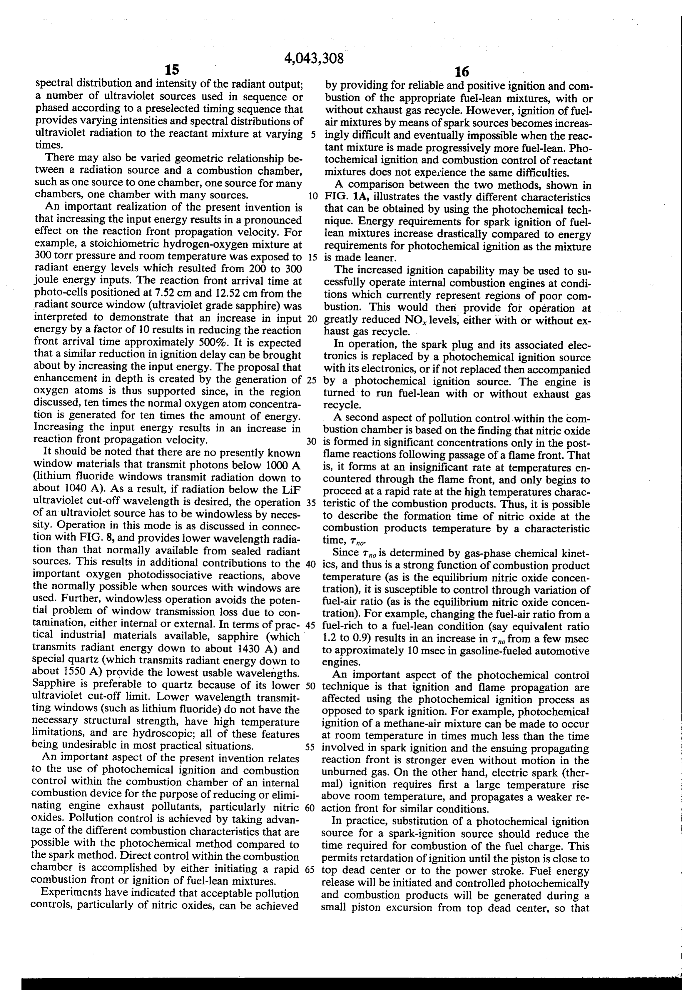
engine efficiency will be essentially unaltered. How 1. In a method of controlling the initiation of combus ever, since the combustion can be timed to occur near tion and controlling combustion in a mixture that in or at the start of the power stroke, significant expansion cludes fuel and an oxidizer, the step comprising irradiat will take place before very much nitric oxide can be ing the mixture with ultraviolet energy sufficient to produced. precondition the mixture by the photodissociative cre Still another application of the method of photochem trationofbelow ation a combustion intermediary species in a concen that required for the photochemical initia ical initiation and control of combustion within the combustion chamber of an engine is to provide for oper tion of combustion at the temperature of the mixture but ation of engines outside their normal limits. For exam 10 above the concentration of said species that would exist ple, the design of aircraft combustors are limited by the at the thermal ignition temperature of the mixture, in requirements of spark ignition and normal combustion which said mixture is contained within the combustion characteristics. Photochemical ignition permits opera chamber of an internal combustion engine. tion at conditions not normally possible, thus extending 2. In a method of controlling the initiation of combus the possible design range. tion and controlling combustion within an internal com Yet another application of the method of photochemi 15 bustion engine supplied with a combustible fuel/air cal initiation and control of combustion is to provide for mixture, the step comprising irradiating the mixture the treatment of engine or chemical process exhaust gas with ultraviolet energy in the region below 2450 A and products. For example the three main pollutants from of sufficient intensity of initiate combustion at a temper engine emissions are unburned hydrocarbons, carbon ature below the thermal ignition temperature of the monoxide and oxides of nitrogen. They result as a con 20 mixture.
3. A method according to claim 2 in which the engine sequence of the inability of the combusting hydrocar bon-air mixture to maintain equilibrium burning rates is 4.anApparatus automotive engine.
for controlling the initiation for combus during the expansion process in the combustion cham ber. Further combustion and burning of these species by tion and controlling combustion in a combustible mix photochemically catalyzing combustion reactions 25 ture, comprising a combustion chamber for receiving within the exhaust manifold of the machine is possible said combustible mixture, and a plurality of sources of due to the enhanced combustion characteristics pro ultraviolet energy positioned to irradiate the mixture vided by the photochemical method. within said chamber with ultraviolet energy, in which The invention, described above, is to be defined by the combustion chamber k k is kin an
automotive
engine.
the following claims. What is claimed is: 30

Provenance
- Collection
- Cited prior art
- Original PDF
- patentimages.storage.googleapis.com →
- Filed
- 1976-04-27
- Pages
- 13
- Method
- pdftotext (the PDF's own text layer) + pdftoppm 300dpi page scans
- Source
- Google Patents bibliographic record
- Granted
- 1977-08-23
- Inventors
- Anthony E. Cerkanowicz; PHOTOCHEM IND Inc
- Transcribed from
- patentimages.storage.googleapis.com →